Note: Descriptions are shown in the official language in which they were submitted.
CA 02564577 2006-10-19
1
Support means system with drive pulley and support means as well as lift
installation with such a support means system
The subject of the invention is a support means system, which comprises a
drive pulley
and a belt-like support means and serves for moving a load, as well as a lift
installation
with such a support means system. Fields of use for such a support means
system are,
for example: supporting and drive systems for cages of passenger and goods
lifts, for
mining conveying equipment, for lifting devices of high-bay warehouse
vehicles, for lifting
devices of stacking vehicles, for lifting equipment in conveying systems of
production lines
and packaging lines, for brush lifting equipment in washing installations, for
lifting
equipment in fitness training apparatus, etc. The support means system is also
suitable
for, for example, use as a conveyor belt of belt conveyors or belt excavators.
The support means system according to the invention is described in the
following on the
basis of use thereof as a support means system of a lift installation.
Lift installations usually comprise a lift cage and a counterweight, which are
movable in a
lift shaft or along free-standing guide devices. For generating the movement,
the lift
installation comprises a drive unit with at least one drive element in the
form of a drive
pulley, wherein the drive pulley supports the lift cage and the counterweight
by way of at
least one flexible supporting and/or drive means and transmits the requisite
drive forces
thereto. Necessary additional deflections of the supporting and drive means
are usually
realised by deflecting elements in the form of deflecting pulleys.
The supporting and/or drive means is termed simply support means in the
following and
where the description refers not only to drive pulleys, but also to deflecting
pulleys these
are called support means pulleys. However, it is not essential for the drive
means pulleys
to have an actual pulley shape; these can also have the shape of a shaft or
axle.
A lift installation is known from EP 1 555 234 Al in which wedge-ribbed belts
are used in
support means for the lift cage. These belts comprise a belt body of flat-belt
kind, which is
produced from resilient material (rubber, elastomer) and which has on the
running surface
thereof facing the drive pulley several ribs extending in belt longitudinal
direction. These
ribs co-operate with corresponding grooves in the periphery of drive or
deflecting pulleys in
order on the one hand to guide the wedge-ribbed belts on the support means
pulleys and
CA 02564577 2006-10-19
2
on the other hand to increase the traction capability between the drive pulley
and the
support means. The ribs and grooves have triangular or trapezium-shaped, i.e.
wedge-
shaped, cross-sections. Tensile carriers consisting of metallic or non-
metallic strands are
embedded in the belt bodies of the wedge-ribbed belts to be oriented in belt
longitudinal
direction and impart the requisite tensile strength and longitudinal stiffness
to the support
means.
The lift installation disclosed in EP 1 555 234 Al, in which wedge-ribbed
belts are used as
support means, has certain disadvantages. One of the disadvantages consists in
that the
wedge-ribbed belt does not attain an optimum drive capability and the
resulting drive
capability does not remain constant in the course of the operating life. This
problem
results from the fact that a substantial part, which is not, however, constant
in the course
of the operating time, of the radial forces transmitted by the wedge-ribbed
belt to the drive
pulley is transmitted not by way of the inclined flanks of the ribs and
grooves, but in the
region of the rib crests and groove bases in approximately radial direction
because the rib
crests rest in the corresponding groove bases. This part of the radial forces,
which is not
clearly determinable and not constant, is not converted, or is converted only
to a small
extent, by wedge action between the inclined flanks into increased normal
forces between
belt and drive pulley. Moreover, in the case of the support means described in
the cited
state of the art the problem exists that dirt and belt abraded material are
collected and
compacted in the grooves of the support means pulleys and also in the grooves
of the
support means. This on the one hand has a consequence that at least in places
the direct
contact between the support means pulley and the belt is prevented, which
strongly
reduces the traction capability between a belt pulley and the support means.
On the other
hand, a thick contamination hardened in the groove base prejudices lateral
guidance of the
support means on the support means pulleys and in the extreme case leads to
the support
means being laterally displaced relative to the support means pulley or even
the running
surface leaving the support means pulley. Not only the loss of drive
capability, but also the
lateral displacement or the jumping-off of the support means from the support
means
pulley can lead to serious operational disturbances of the lift installation.
A further disadvantage of the support means disclosed in EP 1 555 234 Al is to
be seen in
the fact that faultless co-operation between the wedge-shaped ribs and grooves
of the
support means and the corresponding ribs and grooves of the support means
pulley is
disturbed when the support means is used in conjunction with support means
pulleys
CA 02564577 2013-11-08
3
having an extremely small outer diameter. The reason for that is to be seen in
the fact that
as a consequence of the high compressive stresses resulting as a consequence
of support
means curvature in the region of the rib crests of the support means the ribs
deform in
such a manner that they are displaced out of their correct position in the
wedge-shaped
grooves of the support means pulley. If the support means pulley is a drive
pulley a
reduction in traction capability can result therefrom.
The present invention has the object of creating a support means system of the
kind
described in the foregoing in which the stated disadvantages are not present.
Moreover,
the support means system shall be economic and save material.
Accordingly, in one aspect the present invention resides in a support means
system, in
which a support means pulley drives or deflects at least one support means
belt
supporting a load, wherein the support means belt has in the region of a
running surface
facing the support means pulley at least one rib which extends in a
longitudinal direction of
the support means belt and which has a wedge-shaped cross-section with
inclined flanks,
and the support means pulley has in the region of its periphery at least one
corresponding
groove which extends in a circumferential direction and which similarly has a
wedge-
shaped cross-section with inclined flanks and co-operates with the at least
one rib of the
support means belt, wherein: the at least one rib of the support means belt
has a flattened
rib crest and the at least one corresponding groove of the support means
pulley has a
groove base with an encircling slot formed therein, said encircling slot
having a wall joining
the inclined flanks of the at least one corresponding groove at an angle of
inclination
different from an angle of inclination of the joined inclined flanks, said rib
crest and said
slot being configured to form a cavity therebetween when the support means
belt rests on
the support means pulley.
In another aspect the present invention resides in an elevator installation
with a support
means system for supporting and driving an elevator car comprising: a support
means belt
for supporting a load, wherein said support means belt has a running surface
with a
plurality of ribs and grooves which extend in a longitudinal direction of the
support means
belt and which have a wedge-shaped cross-section with inclined flanks; and a
support
means pulley having formed in a periphery a plurality of corresponding grooves
and ribs
which extend in a circumferential direction and which similarly have a wedge-
shaped
cross-section with inclined flanks and co-operate with said ribs and grooves
of said
CA 02564577 2013-11-08
3a
support means belt; wherein at least one of said ribs of said support means
belt has a
flattened rib crest and said corresponding groove of said support means pulley
has a
groove base with an encircling slot formed therein, said encircling slot
having a wall joining
said inclined flanks of said corresponding groove at an angle of inclination
different from
an angle of inclination of said joined inclined flanks, said rib crest and
said slot being
configured to form a cavity therebetween when said support means belt rests on
said
support means pulley.
In a further aspect the present invention resides in a support means system,
in which a
support means pulley drives or deflects at least one support means belt
supporting a load,
wherein: the support means belt has in a region of a running surface facing
the support
means pulley at least one rib and at least one groove each of which extends in
a
longitudinal direction of the support means belt and which has a wedge-shaped
cross-
section with inclined flanks; the support means pulley has in a region of its
periphery at
least one groove and at least one rib each of which extends in a
circumferential direction
and which has a wedge-shaped cross-section with inclined flanks, said at least
one rib of
said support means belt co-operating with said at least one groove of said
support means
pulley and said at least one rib of said support means pulley co-operating
with said at least
one groove of said support means belt; said at least one rib of said support
means belt has
a flattened rib crest and said at least one groove of said support means
pulley has a
groove base with a circumferential slot configured to form a cavity in co-
operation with said
flattened rib crest when the support means belt rests on the support means
pulley, said
slot having a wall joining said inclined flanks of said at least one groove of
said support
means pulley at an angle of inclination different from an angle of inclination
of said joined
inclined flanks; and said at least one rib of said support means pulley has a
rounded rib
crest and said at least one groove of said support means belt has a rounded
groove base
configured to form a cavity in co-operation with said rounded rib crest when
the support
means belt rests on the support means pulley.
The proposed solution substantially consists in that in the case of a support
means system
with a support means, which is of flat-belt type and which in the region of a
running surface
facing the drive pulley has at least one rib or groove which extends in the
longitudinal
direction of the support means and which co-operates with a corresponding
groove or rib
present in the support means pulley, the rib crest and/or the groove base at
the support
means or at the support means pulley is or are so formed that a cavity is
present between
CA 02564577 2013-11-08
3b
the rib crest and the corresponding groove base when the support means rests
on the
support means pulley. It is achieved by this measure that no rib crest rests
in the
corresponding groove base, so that the radial forces mentioned in the
foregoing are
transmitted not in the region of the rib crest and/or the groove base, but by
way of the
inclined flanks of the rib or the groove, that contaminations in the cavity
are conducted
away to where they cannot have any harmful effects and that the ribs of the
support
means can slightly expand in the cavity when their internal compressive
stress, which is
caused by the support means curvature, has reached a certain level.
Constant and defined traction values between a support means pulley acting as
a drive
pulley and the support means can be achieved if in the case of a support means
resting on
the support means pulley a rib or a groove of the support means contacts the
CA 02564577 2006-10-19
4
corresponding groove or rib of the support means pulley exclusively in the
region of the
inclined flanks thereof.
A particularly simple form of embodiment of the invention consists in that the
rib crest of
the rib of the support means and/or of the rib of the support means pulley is
flattened in
order to produce the cavity.
In a particularly wear-resistant form of embodiment of the invention the rib
crest of the rib
of the support means and/or the rib crest of the rib of the support means
pulley is provided
with a rounding in order to produce the cavity, wherein the rounding radius of
this rounding
is greater than the rounding radius of any rounding which may be present at
the groove
base of the corresponding groove.
A form of embodiment particularly effective against contamination consists in
that the
groove base of the groove of the support means pulley has an encircling slot
in order to
produce the cavity, i.e. the groove base of the wedge-shaped groove of the
support means
pulley is deepened by an encircling slot.
Advantageously, the encircling slot has a rectangular or semicircular cross-
section.
According to a particularly preferred form of embodiment of the invention the
support
means has several parallelly arranged ribs or grooves with inclined flanks,
which
correspond with several parallel grooves or ribs with inclined flanks at the
support means
pulley, wherein the support means resting on the support means pulley under
tensile
stress contacts this exclusively in the regions of the inclined flanks.
Advantageous characteristics with respect to traction capability and lateral
guidance of the
support means on the support means pulley are achieved if the flank angle (13)
present
between the flanks of the ribs and grooves is at least 600 and at most 1200.
Excellent characteristics with respect to low noise and vibration-free running
of the support
means on the support means pulley are achieved if in the case of a support
means with
several ribs and grooves the widths of the said cavities are so selected that
the sum of the
widths, which are projected onto the axis of the support means pulley, of all
contacting
flanks of the wedge-shaped ribs or grooves is at most 70% of the total width
of the support
CA 02564577 2006-10-19
means.
In advantageous manner the fact that the cavities in the region of the groove
crests of the
support means enable minimisation of the minimum radius of curvature
permissible for
these support means is utilised in such a manner that the support means pulley
has an
outer diameter of less than 80 millimetres, preferably of less than 65
millimetres.
According to a particularly material-saving and economic form of embodiment of
the
invention the support means pulley serving as drive pulley is integrated in
the driven shaft
of a drive unit or coupled in the form of a support means drive shaft with the
driven shaft.
In both cases the drive pulley has the form of a shaft which is provided with
at least one rib
or groove and which can have a minimum outer diameter because thanks to the
cavities
according to the invention between corresponding rib crests and groove bases
the
compressive stress, which arises in the ribbed crests due to the small support
means
curvature, is diminished and thereby the occurrence of slip is reduced.
Examples of embodiment of the invention are explained on the basis of the
accompanying
drawings, in which:
Fig. 1 shows a section through a lift installation according to the invention
with a support
means according to the invention;
Fig. 2 shows an isometric view of a support means with several ribs and
grooves
according to a known state of the art;
Fig. 3 shows a section through a first form of embodiment of a support means
according
to the known state of the art;
Fig. 4 shows a section through a second form of embodiment of a support means
according to the known state of the art;
Fig. 5 shows a section through a form of embodiment according to the invention
of a
support means;
Fig. 6 shows a section through the periphery of a support means pulley
according to the
CA 02564577 2006-10-19
6
invention for the support means according to the invention;
Fig. 7 shows a section through a belt pulley according to the invention and a
support
means according to the invention resting thereon; and
Fig. 8 shows an enlarged detail of Fig. 7.
Fig. 1 shows a section through a lift system according to the invention, which
is installed in
a lift shaft 1, with a support means according to the invention. Essentially
there are
illustrated:
a drive unit 2, which is fixed in the lift shaft 1, with a drive pulley 4.01,
a lift cage 3, which is guided at cage guide rails 5, with cage support
pulleys 4.02
mounted below the cage floor 6,
a counterweight 8, which is guided at counterweight guide rails 7, with a
counterweight support pulley 4.03 and
a belt-like support means 12, with at least one rib or groove extending in its
longitudinal direction, which support means supports the lift cage 3 and the
counterweight 8 and transmits the drive force from the drive pulley 4.01
thereto (in
the case of an actual lift installation at least two support means arranged in
parallel
are present).
The belt-like support means 12 is fastened at one of its ends below the drive
pulley 4.01 to
a first support means fixing point 10. From this it extends downwardly to the
counterweight support pulley 4.03, loops around this and extends from this out
to the drive
pulley 4.01, loops around this and runs downwardly along the cage wall at the
counterweight side, loops around, on either side of the lift cage, a
respective cage support
4.02, which is mounted below the lift cage 3, in each instance through 90 and
runs
upwardly along the cage wall remote from the counterweight 8 to a second
support means
fixing point 11.
The plane of the drive pulley 4.01 is arranged at right angles to the cage
wall at the
counterweight side and its vertical projection lies outside the vertical
projection of the lift
cage 3. It is therefore important that the drive pulley 4.01 has a small
diameter so that the
spacing between the lefthand cage wall and the wall, which is opposite
thereto, of the lift
shaft 1 can be as small as possible. Moreover, a small drive pulley diameter
enables use
CA 02564577 2006-10-19
7
of a gearless drive motor with a relatively low drive torque as drive unit 2.
The drive pulley 4.01 and the counterweight support pulley 4.03 are provided
at their
periphery with grooves formed to be complementary to the ribs of the support
means 12.
Where the support means 12 loops round one of the support means pulleys 4.01
and 4.03
its ribs lie in corresponding grooves of the support means pulley, whereby a
perfect
guidance of the support means on these drive means pulleys is guaranteed.
Moreover,
the traction capability is improved by an wedge effect arising between the
grooves of the
support means pulley 4.01, which serves as drive pulley, and the ribs of the
support
means 12.
In the case of support means under-looping below the lift cage 3 there is no
lateral
guidance between the cage support pulleys 4.02 and the support means 12, since
the ribs
of the support means are disposed on its side remote from the cage support
pulleys 4.02.
In order to nevertheless ensure lateral guidance of the support means, two
guide pulleys
4.04 provided with grooves are mounted at the cage floor 6, the grooves of
these pulleys
co-operating with the ribs of the support means 12 as lateral guide.
Fig. 2 shows a detail of a wedge-ribbed belt 12.1, which serves as support
means, of a lift
installation according to the previously stated document with regard to the
state of the art.
The belt body 15.1, several wedge-shaped ribs 20.1 and grooves 21.1 and the
tensile
carriers 18.1 embedded in the belt body can be recognised.
Fig. 3 shows a cross-section through a first support means 12.1 as is known
from the cited
document with respect to the state of the art. It comprises a belt body 15.1
and several
tensile carriers 18.1 embedded therein. The belt body 15.1 is made of a
resilient material.
Natural rubber or a plurality of synthetic elastomers, for example, is usable.
The flat side
of the belt body 15.1 can be provided with an additional cover layer or a
worked-in fabric
layer. The traction side, which co-operates with a drive pulley and optionally
with
deflecting pulleys, which are both termed support means pulleys in the
following, of the
belt body 15.1 have several web-shaped ribs 20.1 and grooves 21.1 extending in
longitudinal direction of the support means 12.1. A support means pulley 4.1
is indicated
by means of ghost lines, in the periphery of which with the outer diameter D
are formed
grooves 23.1 and ribs 22.1 corresponding with the ribs 20.1 and grooves 21.1
of the
support means 12.1.
CA 02564577 2006-10-19
8
Fig. 4 shows a cross-section through a similar support means 12.1 similarly
known from
the cited document with respect to the state of the art, the wedge-shaped ribs
in the
support means being formed to be wider than the grooves. A basic construction
and
function of this support means, however, correspond with those of the support
means
shown in Fig. 3. The outer profile of a support means pulley 4.2 with grooves
23.2 and
ribs 22.2 corresponding with the ribs 20.2 and grooves 21.2 of the support
means 12.2 is
also illustrated in Fig. 4 by ghost lines.
It is clearly recognisable from Figs. 3 and 4 that in the case of both forms
of embodiment
according to the known state of the art the grooves 23.1; 23.2 and ribs 22.1;
22.2 of the
support means pulleys 4.1, 4.2 are formed to be fully complementary to the
corresponding
ribs 20.1; 20.2 and grooves 21.1; 21.2 of the support means 12.1, 12.2. This
has the
consequence that in operation the support means contacts the support means
pulley along
the entire cross-sectional profile formed by the ribs and grooves of the
support means and
the support means pulley, which has the consequence of the disadvantages
described in
the introduction and in the following.
As is generally known, a support means pulley used as drive pulley can
transmit traction
forces to a support means in the manner that the support means is radially
pressed
against the periphery of the drive pulley, wherein the attainable traction
force corresponds
with the product of the sum of the normal forces, which arise between the
drive pulley and
the support means, and the coefficient of friction which is present.
Radial force components transmitted in the region of the inclined flanks of
the ribs 20.1,
22.1; 20.2, 22.2 and grooves 21.1, 23.1; 21.2, 23.2 are amplified by the wedge
effect
between the flanks to produce higher normal forces which act on the flanks and
which can
produce higher traction forces than the radial force components transmitted
substantially in
radial direction. Since in the case of corresponding ribs and grooves, which
are formed to
be fully complementary, of the support means and the support means pulley it
is not
clearly defined which proportion of the radial forces, which arise between the
support
means and support means pulley, is transmitted in the region of the inclined
flanks of the
ribs and grooves and which proportion is transmitted in approximately radial
direction in
the region of the rib crests and groove bases, in the case of a support means
pulley
serving as a drive pulley the resultant traction force on the one hand is not
determinable
CA 02564577 2006-10-19
9
with sufficient accuracy in advance and on the other hand as a consequence of
plastic
changes in shape and abrasion at the drive means is not constant over a longer
operating
period.
Moreover, it is readily apparent from Figs. 3 and 4 that dirt and abraded
material can
collect in the grooves of the support means pulley 4.1; 4.2 as also in the
grooves of the
support means 12.1; 12.2 and are compacted and hardened by the tensioned
support
means. The traction capability and also the lateral guidance between the
support means
pulley and the support means can thereby be strongly prejudiced, which can
have the
consequence of serious operational disturbances.
A section through a support means 12.3 according to the invention is
illustrated in Fig. 5
and the corresponding periphery of a support means pulley 4.3 according to the
invention
is illustrated in Fig. 6. Fig. 7 shows a section through the support means
12.3 according to
Fig. 5 and the support means pulley 4.3 according to Fig. 6 in a state in
which the support
means is, as a consequence of its loading in tension, pressed against the
support means
pulley. Fig. 8 shows an enlarged detail of Fig. 7 so as to make details
recognisable.
The support means 12.3 illustrated in Figs. 5 to 8 comprises a belt body 15.3
and several
tensile carriers 18.3 embedded therein. The belt body 15.3 is made of a
resilient material.
Natural rubber or a number of synthetic elastomers, for example, is usable.
The flat side
17 of the belt body 15.1 can be provided with an additional cover layer 25.3,
preferably a
fabric layer. The support means 12.3 has several ribs and grooves which extend
in its
longitudinal direction and which on the one hand serve for lateral guidance of
the support
means on a support means pulley 4.3 and on the other hand improve the traction
capability between the support means pulley and support means when the support
means
pulley is used as drive pulley.
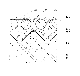
It can be inferred from Figs. 5 to 8 that the grooves 23.3 and ribs 22.3 of
the support
means pulley are not formed to be completely complementary to the
corresponding ribs
20.3 and grooves 21.3 of the support means. In the regions in which the rib
crests 30; 31
are opposite the groove bases 32; 33 cavities 34, 35 are present so that it is
ensured that
when the support means 12.3 is resting on the support means 4.3 the ribs
(20.3) and
grooves (21.3) of the support means (12.3) and the corresponding ribs (23.3)
and the
corresponding ribs (22.3) of the support means 4.3 contact one another
exclusively in the
CA 02564577 2006-10-19
region of the inclined flanks (28; 29) thereof. The radial forces acting
between the support
means 12.3 and the support means pulley 4.3 are through these measures
transmitted
with certainty exclusively by way of the inclined flanks 28; 29 of the ribs
and grooves,
which have a constant and uniform flank angle 13. It is therefore ensured that
all radial
force components arising between the support means and the support means
pulley are
amplified, as a consequence of the wedge effect caused by the inclined flanks,
to produce
increased normal forces between the flanks of the support means and the
support means
pulley. In the case of a support means pulley 4.3 serving as a drive pulley
there results
therefrom - as already described in the foregoing - an increased traction
capability which is
constant over a long operating time.
However, the said cavities 34, 35 also have the purpose of receiving
contaminations which
deposit in the course of the lift operation on the traction surfaces of the
support means
12.3 and the support means pulley 4.3. It is thereby achieved that in the case
of use of the
support means pulley as a drive pulley the traction capability is not
prejudiced and that in
the case of all support means pulleys the lateral guidance, which is given by
the co-
operation of ribs and grooves of the support means and the support means
pulley, of the
support means on the support means pulleys is maintained. The cavities 34, 35
can be
cleaned on the occasion of the lift maintenance to be periodically carried
out.
As shown in Figs. 5 to 8, the cavities (34, 35) required in accordance with
the invention in
the region of mutually opposite rib crests (30; 31) and rib bases (32; 33) can
be produced
in different ways. In the interests of simplified illustration different forms
of embodiment of
the measures for producing cavities at the same support means and the same
support
means disc are shown in Figs. 6 to 8.
In the case of a particularly simple form of embodiment the rib crests 30 of
the support
means 12.3 or the rib crests 31 of the support means pulley 4.3 are for this
purpose
flattened.
According to a further form of embodiment, which is recognisable particularly
from Fig. 8,
cavities 34 are produced in that the rib crests 30 of the ribs 20.3 of the
support means 12.3
or the rib crests 31 of the ribs 22.3 of the support means pulley 4.3 are
provided with a
rounding, wherein the rounding radius of this rounding is substantially
greater than the
rounding radius of a rounding which may happen to be present at the groove
base of the
CA 02564577 2006-10-19
11
corresponding groove. Not only the rib crests of the support means, but also
the rib crests
of the support means pulley can be provided with such roundings. The forms of
embodiment with strongly rounded rib crests have provided to be particularly
low in wear
and are distinguished by good running smoothness.
In the case of a form of embodiment, which is particularly suitable for
elimination of
contamination problems, of the invention the groove bases 33 of the wedge-
shaped
grooves 23.3 of the support means pulley 4.3 are deepened by encircling slots
36, 37 in
the support means pulley, as is apparent particularly from Fig. 8. Such slots
have the
advantage that they can accept a substantial quantity of dirt. Advantageously,
the slots
36, 37 have rectangular or semicircular cross-sections.
The widths, which are projected onto the axis of the support means pulley, of
the inclined
contact surfaces between the support means 12.3 and the support means pulley
4.3 are
denoted in Fig. 8 by B. Tests have shown that it is advantageous to limit the
sum of the
widths (B), which are projected onto the axis of the support means pulley
(4.3), of all
contacting flanks of the ribs and grooves, respectively, to at most 70% of the
total width of
the support means (12.3). It is thus achieved on the one hand that on every
occasion all
contact surfaces of the support means stand in full contact with the
corresponding contact
surfaces of the support means pulley, whereby an optimum stable, low-vibration
and low-
noise running of the support means 12.3 is achieved. Moreover, a sufficient
area pressing
in the region of the contact surfaces is ensured by the limitation of the
projected total width
of the contact surfaces. This pressing has, in the case of a drive pulley, the
consequence
of a lesser negative influencing of the traction behaviour due to
contamination such as oil,
rust, dust grains, etc., since the contamination components due to the high
area pressing
are either displaced out of the contact region (preferably into the mentioned
cavities) or -
for example in the case of relatively coarse dust grains - forced by the drive
pulley into the
resilient material of the support means 12.3, so that the contact between the
support
means and the drive pulley 4.3 is maintained as best as possible.
The limitation of the said projected total width of the contact surfaces is
preferably carried
out by a selection of the width of the cavities 34, 35 according to the
invention between
corresponding rib crests and groove bases.
The cavities 34, 35 according to the invention between corresponding rib
crests and
CA 02564577 2006-10-19
12
groove bases have a further advantageous effect. In the case of a strong
support means
curvature the ribs 20.3 of the support means 12.3 are exposed in the region of
the rib
crests 30 to high compressive stresses, which have a consequence that the ribs
bulge out
in the said region. This has the consequence that the ribs and the support
means due to
the wedge action between the inclined flanks are raised relative to the
support means
pulley 4.3, whereby the full contact between the ribs and grooves of the
support means
and the ribs and grooves of the support means pulley is lost. Resulting
therefrom are
increased slip between a support means pulley, which is used as drive pulley,
and the
support means, high support means wear and unsmooth running of the support
means in
the region of all support means pulleys.
The afore-mentioned cavities 34, 35 make it possible for the ribs of the
support means to
expand somewhat in the region of their rib crests into these cavities, whereby
there is
substantial mitigation of the described problem with small radii of curvature.
This measure
makes a significant contribution to the support means according to the
invention being
able to be used in combination with support means pulleys with extremely small
outer
diameters. In concrete terms use can be made, as drive and deflecting pulleys,
of support
means pulleys having an outer diameter in the normal case of less than 80
millimetres, but
if required even smaller than 65 millimetres. This makes it possible to
integrate the drive
pulley in the driven shaft of a drive unit or to couple it, in the form of a
support means drive
shaft, with the driven shaft of the drive unit.
In the case of the form of embodiment, which is shown in Figs. 5 to 8, of the
invention the
support means 12.3 has several parallel ribs and grooves which are arranged to
be
distributed over the entire width of the support means. However, a support
means
according to the invention can also be provided with only a single rib or
groove, which
obviously also applies to the corresponding support means pulley.
Advantageously, such
a rib or groove in the case of the support means is arranged in the middle of
the support
means width, wherein the width of the rib or the groove is greater than and
has a similar
form to the ribs 20.2 of the support means illustrated in Fig. 4.
The support means illustrated in Figs. 5 to 8 has a preferred flank angle f3
of approximately
90 . Tests have shown that the flank angle (3 has a decisive influence on the
development
of noise and the creation of vibrations in the support means and that flank
angles p of 80
to 100 are optimal for a lift support means. In the case of flank angles p of
less than 60
CA 02564577 2006-10-19
13
the support means has a tendency to vibrations and at flank angles 13 of more
than 1000
the security against lateral displacement of the support means on the support
means
pulley is no longer guaranteed.
The support means system according to the invention is described in the
foregoing in
conjunction with use in a lift installation in the sense of an example and not
in the sense of
a limitation. The expert will, with knowledge of the invention, recognise
further variants of
use and embodiment lying within the field of protection of the patent claims.