Note: Descriptions are shown in the official language in which they were submitted.
CA 02564915 2006-10-23
1
1NTERACTIVE TOY SYSTEM
Inventor: YU ZHENG
BACKGROUND OF THE INVENTION
1. Field of the Invention
The present invention relates to toys, and in particular, to an interactive
toy
system.
2. Description of the Prior Art
Interactive toys have become increasingly popular in recent times. Children
enjoy playing with toys that communicate or respond to different selections or
prompts from the player. For example, United States Patent Nos. 6,663,393
(Ghaly)
5,607,336 (Lebensfeld et al.), 6,648,719 (Chan) and 6,585,556 (Smirnov) all
disclose
toys, dolls or action figures who act or respond based on some activation by
the
user, or by the surrounding events.
SUMMARY OF THE DISCLOSURE
It is an object of the present invention to provide an interactive toy system
which allows the user to enact real-life activities of a doll, animal, action-
figure or
similar creature.
It is another object of the present invention to provide an interactive toy
system which provides a wide variety of responses and play.
It is yet another object of the present invention to provide an interactive
toy
system which provides different responses based on different selections made
by the
user.
In order to accomplish the objects of the present invention, the present
invention provides systems and methods for interactive play, including a
method of
interacting with an action figure. The method of the present invention
includes the
steps of (i) providing a base unit having a processor, (ii) providing an
action figure
having a memory which stores data relating to the action figure, (iii)
communicating
the data in the form of communication signals to the processor, and (iv)
presenting
an activity instruction based on the communication signals received, with the
activity
instruction enacting a real-life activity that the action figure can engage
in.
BRIEF DESCRIPTION OF THE DRAWINGS
CA 02564915 2006-10-23
i =
2
FIG. 1 is a perspective view of an interactive doll system according to one
embodiment of the present invention with the doll shown positioned in the doll
station.
FIG. 2 is a front perspective view of the doll station of the system of FIG.
1.
FIG. 3 is a rear perspective view of the doll station of the system of FIG. 1.
FIG. 4 is an exploded perspective view of the base of the doll station of FIG.
1.
FIG. 5 is a block diagram illustrating the electrical components of the system
of FIG. 1.
FIG. 6 is a rear perspective view of a doll according to one embodiment that
can be used with the system of FIG. 1.
FIG. 7 is a flow chart illustrating one possible flow of operation for the
system
of the present invention.
FIG. 8A illustrates a chip that can be used in connection with an accessory
according to the present invention.
FIGS. 8B-8G illustrate various accessories that can be used with the system
of the present invention.
FIG. 9 is a perspective view of a multi-doll system that utilizes the
principles of
the present invention.
FIG. 10A is a perspective view of an interactive doll system according to
another embodiment of the present invention.
FIG. 10B is a block diagram illustrating the electrical components of the
system of FIG. 10A.
FIG. 11 is a perspective view of an interactive toy system according to
another
embodiment of the present invention.
FIGS. 12A-12C illustrate various accessories that can be used with the toy
system of FIG. 11.
FIG. 13 illustrates modifications that can be made to the teddy bear in the
system of FIG. 11.
FIG. 14 is a block diagram illustrating the electrical components of the
system
of FIG. 13.
FIG. 15 is an exploded perspective view of a toy system according to yet
another embodiment of the present invention.
CA 02564915 2006-10-23
3
FIG. 16 is a block diagram illustrating the electrical components of the
system
of FIG. 15.
FIG. 17 is a flow chart illustrating one possible flow of operation for the
system
of FIGS. 15-16.
FIG. 18 illustrates an example of a play activity that can involve the
incorporation of accessories.
FIG. 19 is a perspective view of the interactive doll system of FIG. 10A with
modifications made thereto.
FIG. 20 is a perspective view of an interactive doll system according to
another embodiment of the present invention.
FIG. 21 is a block diagram illustrating the electrical components of the
system
of FIG. 20.
FIG. 22 is a block diagram of the base station in FIG. 21.
DETAILED DESCRIPTION OF THE PREFERRED EMBODIMENTS
The following detailed description is of the best presently contemplated modes
of carrying out the invention. This description is not to be taken in a
limiting sense,
but is made merely for the purpose of illustrating general principles of
embodiments
of the invention. The scope of the invention is best defined by the appended
claims.
As used herein, the term "doll" is not limited solely to a fashion doll or
play
doll, but encompasses figurines, action figures, toy animals, plush toys,
miniature
animals, or any miniaturized or toy version of any living creature.
The present invention provides an interactive toy system which allows the
user to enact real-life activities of a doll, animal, action-figure or similar
creature.
More specifically, the present invention provides a toy system 20 which
provides for
interactive play between the system 20 and the user. The user can select
different
play programs which will program the doll or toy with certain emotions,
responses or
characters, and which will allow or direct the user to enact selected real-
life activities
for the doll or toy.
According to one embodiment of the present invention, the doll or toy merely
functions as an object that is used by the player to enact selected real-life
activities,
and does not communicate or interact with the player. According to this
embodiment, the player communicates solely with a base unit or doll station,
which
provides instructions or messages to the player regarding how the real-life
activities
CA 02564915 2006-10-23
4
are to be enacted. The player then utilizes the doll or toy to carry out the
enactment.
In this embodiment, the doll or toy may communicate interactively with the
base unit
or doll station, but will not communicate directly with the player.
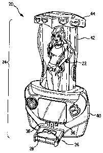
FIG. 1 illustrates the basic components of an interactive doll system 20
according to one embodiment of the present invention. In its most basic form,
the
system 20 includes a doll 22, a doll station 24 and a storage device 26.
However, as
explained hereinbelow, the system 20 can also include a plurality of dolls 22,
a
plurality of doll stations 24, and a plurality of storage devices 26, all of
which can be
utilized to create a multi-variety interactive game system.
The storage device 26 can have a housing 28 that houses any conventional
and well-known medium that includes a memory 30 (see FIG. 5) for storing
digital
data. The memory 30 can be embodied in the form of a memory card or cartridge
or
any other conventional storage medium, including a RAM, a ROM, or any
writeable
memory. The housing 28 can be ornamentally configured according to a given
theme (e.g., princess theme) for the system, and can also include a
communication
(e.g., input/output) port 32 which is adapted to be removably coupled to a
communication (e.g., input/output) port 34 at the doll station 24. The memory
30 can
be adapted to store programs (software) for controlling the operation of the
doll
station 24, as described below. The memory 30 can also be adapted to store
data
that can be transferred to the doll station 24. Such data can include verbal
or written
messages, pre-recorded statements, sounds, music, light shows and other
similar
responses that can be displayed on the display screen 36 at the doll station
24, or
emitted from the speaker 38 at the doll station 24. As used herein, the
display
screen 36 and the speaker 38 are mechanisms used by the system 20 to present a
message. In addition, the system 20 can provide a plurality of different
storage
devices 26, with each storage device 26 storing software and/or data for
different
applications. For example, one storage device 26 can contain software and data
directed to a princess doll application, another storage device 26 can contain
software and data directed to a beach application, another storage device 26
can
contain software and data directed to a party application, and another storage
device
26 can contain software and data directed to a safari application, among
others. The
player can vary his/her play variety by selecting the desired storage device
26 for a
desired application.
CA 02564915 2006-10-23
In addition, the storage device 26 can be coupled to a personal computer PC
(see FIG. 5) to download new programs (either from the PC or from the
Internet) that
can be used to play the system 20. In this regard, the storage device 26 can
be
embodied in the form of a CD or other diskette.
5 The doll station 24 is adapted to hold a doll 22 during use. Referring to
FIGS.
2-3, the doll station 24 has a base 40, a rear wall 42, and a roof 44.
Referring to
FIG. 4, the base 40 has a base housing 46 and a front panel 48. The base
housing
46 defines an interior space 50 for holding the doll 22, and has an opening 52
in its
front wall 54 for receiving the front panel 48. The front panel 48 houses the
electronics (see FIG. 5) of the doll station 24, which includes a processor 56
and a
memory 58. The memory 58 can be used to store basic operating instructions for
_ the processor56, _ in_which_case.,the memory 58_ canbe.
embodied..in_.the_form_.of a
ROM. Alternatively, the memory 58 can be used to store some or all of the
programs, with the memory 30 on the storage device 26 used primarily for
storing
data that can be utilized to control or change the operation parameters of the
programs stored in the memory 58. Referring to FIGS. 4 and 5, the
communication
port 34, the speaker 38 and the display screen 36 are provided on the front
panel 48,
and are all coupled to the processor 56. The front panel 48 can also include a
control pad 60 and control buttons 62. The port 34 functions to allow data and
instructions to be transferred from the memory 30 in the storage device 26 to
the
processor 56 in the front panel 48. The screen 36 functions to display words,
images, colors, and patterns that are in response to instructions or data
provided by
the storage device 26 or the doll 22. The speaker 38 emits sounds to provide
vocal
instructions and music. The speaker 38 and the screen 36 are both controlled
by the
processor 56. The control pad 60 and the buttons 62 are coupled to the
processor
56 to provide control signals to the processor 56, so that the player can
control the
operation of the system 20 by controlling the pad 60 and the buttons 62. For
example, the player can press selected buttons 62, or control the pad 60, to
select
desired play modes or features, or to perform any of the play functions
described
hereinbelow.
Referring to FIG. 3, the base 40 can be provided with a battery compartment
accessed by a battery cover 64. Conventional batteries 66 (see FIG. 5) can be
housed inside the battery compartment, and coupled to the electronics to power
the
operation of the doll station 24.
CA 02564915 2006-10-23
6
The rear wall 42 extends from the top rear portion of the base 40, and is
slightly curved to define a background wall for the doll 22. An optional
window 68
can be provided in the rear wall 42 for ornamental or functional (e.g.,
provide access)
purposes. In addition, an antenna 70 can be provided in the rear wall 42 (see
FIG.
3), with the antenna 70 coupled to the electronics shown in FIG. 5 via wiring
(not
shown) that extends through the base housing 46 and the front panel 48.
The roof 44 is optional, and can be attached to the top of the rear wall 42 to
provide a cover or shade for the doll 22 when the doll 22 is positioned inside
the
base 22. A handle (not shown) can be provided on top of the roof 44 to provide
a
means for the user to carry the doll station 24.
As shown in FIG. 1, the interior space 50 of the base 40 is adapted to hold a
doll 22 with the doll 22 in the standing position. The doll 22 would be
positioned in
front of the rear wall 42, and below the roof 44. The user can insert the doll
22 into
this interior space via the open front space defined by the roof 44, the base
40 and
the rear wall 42. Even though the present embodiment illustrates the doll 22
as
being positioned in a standing position, it is also possible to size and
configure the
base housing 46, the rear wall 42 and the roof 44 to accomodate the doll 22 in
any
desired position (sitting, standing, etc.).
Referring to FIG. 6, the doll 22 is provided with a chip 72 that is secured in
a
slot 74 that is cut out from the torso 76 of the doll 22. Referring to FIG. 5,
the chip 72
includes a memory 78 that is coupled to a controller 82 that is in turn
coupled to an
antenna 80. The antenna 80 is adapted to communicate with the electronics in
the
base 40 via the antenna 70 in the rear wall 42. In addition, a small battery
84 can be
fitted into part of the slot 74 to power the chip 72. The battery 84 can be
embodied
in the form of a small watch battery. The memory 80 in the doll 22 contains
data
which identifies the doll 22 and certain characteristics of the doll 22. These
characteristics can include the name, age, height, weight, size, likes,
dislikes, mood,
requests, type of voice (low-pitch, high-pitch, soft, loud, etc.), and any
other
characteristic (e.g., shy, outgoing, gregarious, etc.) that can be ascribed to
a doll.
Data corresponding to desired characteristics can be transferred from the
memory
80 to the doll station 24 to activate different responses (e.g., verbal or
written
messages, pre-recorded statements, sounds, music, light shows, etc.) that can
be
displayed on the display screen 36 at the doll station 24, or emitted from the
speaker
38 at the doll station 24. As a further alternative, the memory 78 in the chip
72 can
CA 02564915 2006-10-23
7
even contain programs relating to different activities that the specific doll
22 can
engage in, and these programs can be transferred to the processor 56 during
operation.
When the doll 22 is placed inside the interior space 50 of the base 40, the
antenna 70 and 80 will be positioned adjacent to each other, and be capable of
communicating with each other. In one non-limiting embodiment of the present
invention, the antenna 70 and 80 can be selected to be short-range antennas
that
can only communicate wireless signals over a short distance. The use of such
short-
range antenna would ensure that the doll 22 be positioned in, or in close
proximity to,
the base 40 before that particular doll 22 can be the subject of the activity.
This can
be an effective scheme if the manufacturer provides more than one type of doll
22,
each having an antenna 80. If longer range antennas 70 and 80 were to be used
for
a multi-doll system 20, the antenna 70 at the base 40 could be receiving
signals from
multiple dolls 22, which might confuse the processor 56. Next, the
characteristics of
the doll 22 are transferred to the processor 56 at the doll station 24 (see
step 102
below). In addition, as described below, the user can select a desired
application by
selecting one of a variety of storage devices 26.
FIG. 7 is a flowchart that illustrates one one-limiting example of an activity
flow
for the system 20. In a first step 100, the doll 22 is placed inside the
interior space
50 of the base 40. In step 102, the processor 56 identifies the doll 22 in the
manner
described above, and receives the characteristics of the doll 22. For example,
the
system 20 can be provided with a plurality of different dolls 22 that can all
be used
with the same doll station 24. Thus, the identity of the doll 22 is determined
in step
102. Next, in step 104, the player selects a storage device 26 and inserts it
into the
front panel 48. In step 106, the processor 48 identifies the selected storage
device
26 (e.g., via signals from the memory 30 to the processor 56 that are
communicated
via the ports 32 and 34) and determines whether the selected storage device 26
can
be used with the selected doll 22. For example, some of the storage devices 26
have applications that cannot be used with some of the dolls 22 in the system
20,
and step 106 functions to determine whether the player has selected a
compatible
storage device 26 (i.e., application). If the selected storage device 26 is
not
compatible with the selected doll 22, the processor 48 will cause a message to
be
displayed on the screen 36, or announced through the speaker 38, in step 108,
informing the player that an incompatible storage device 26 has been selected.
If
CA 02564915 2006-10-23
8
the selected storage device 26 is compatible with the selected doll 22, in
step 110,
the processor 48 will download the different software programs from the memory
30
in the storage device 26, and display the various choices in the form of a
menu on
the screen 36. Then, in step 112, the player can select the desired program
for play,
which is then executed in step 114. At the end of the execution of the
selected
program, processing returns to step 112 where the player can again select the
next
program for play.
Even though the flow of the present invention is described as including the
use of a menu displaying various selections of programs, it is also possible
to
provide each storage device 26 with only one selection, so that a menu would
be
unnecessary.
A variety of different programs can be provided for selection by the player.
All
of these programs are adapted to allow the player to enact real-life
activities for the
doll 22, as if the doll 22 were alive and going through the normal daily
activities of a
living doll. These programs can be based on any of the following: (i) the
characteristics of the doll 22 that have been downloaded from the memory 78 on
the
chip 72, (ii) the nature of the environment portrayed by the doll station 24,
and (iii)
the programs and/or theme of the selected storage device 26. These programs
can
also be independent of any of these parameters, and any of these parameters
can
be used together or independent of each other. It is the provision and
selection of
these parameters that allow the player to be able to enact the real-life
activities of the
doll 22. The following are a few non-limiting examples of programs (enacting
activities) that can be stored in the memory 30 and/or 58 and/or 78 for play
on the
doll station 24.
Fxam IRe1
The processor 56 causes the speaker 38 to emit an instruction, such as "I'm
cold, please put a jacket on me". The player then goes to his/her doll
accessories,
takes a doll jacket and dresses the doll 22 with a jacket.
CA 02564915 2006-10-23
9
Exam 1n e 2
The processor 56 causes the speaker 38 to emit an instruction, such as "I
would like to go to the beach". The player then takes the doll 22 out of the
base 40
and takes the doll 22 to another doll station 24 that represents a beach
environment,
and inserts the doll 22 into the base 40 of the beach doll station 24. The
steps
outlined in FIG. 7 are then executed with respect to the beach doll station
24, and
the play continues.
Exam Ip e 3
The processor 56 causes the speaker 38 to emit an instruction, such as "I
would like to play with a friend". The player then takes a different (second)
do1122
and places it adjacent the doll station 24 so that the two dolls 22 can
supposedly play
with each other. The steps outlined in FIG. 7 are executed with respect to the
second doll 22 and the station 24, and the play continues.
Exam Ip e 4
The processor 56 causes the screen 36 to display a colorful message,
accompanied by music from the speaker 38. This performance can reflect the
identity of the doll 22. For example, if the doll 22 is intended to be a happy
doll, the
screen 36 can be caused to display bright and colorful images, and the speaker
38
can broadcast cheerful music. On the other hand, if the doll 22 is intended to
be an
evil doll, the screen 36 can be caused to display malicious or dark images,
and the
speaker 38 can broadcast somber music. These performances can be used to
reflect the attitude, character, emotions or mood of the doll 22.
Example 5
In one non-limiting embodiment of the present invention, the accessories that
accompany the doll 22 can be provided with chips similar to chip 72 that allow
for the
accessory to communicate with the doll station 24. For example, FIGS. 5 and 8A
illustrate a chip 172 that can be provided for use with an accessory. The chip
172
has an antenna 180 that is coupled to a memory 178 and a controller 182, which
can
be the same as the memory 78 and the controller 82, respectively. The antenna
180
allows the chip 172 to communicate with the processor 56 via the antenna 70.
The
memory 178 in the chip 172 stores data identifying the characteristics of the
intended
accessory. The antenna 180 can be the same as the antenna 80, and can be a
short-range antenna.
CA 02564915 2006-10-23
FIGS. 8B-8G illustrate various accessories that incorporate a chip 172, such
as a hat 130 (FIG. 8B), a hair brush 132 (FIG. 8C), a pair of boots 134 (FIG.
8D), a
skirt 136 (FIG. 8E), a blouse 138 (FIG. 8F), and a pair of trousers 140 (FIG.
8G).
Any of these accessories can be used or carried by the doll 22. For example,
the
5 doll 22 could be wearing the blouse 138 when it is placed inside the base
40. The
chip 172 on the blouse 138 would communicate with the processor 56 (via the
antennas 70 and 180) to identify the blouse 138. If the blouse 138 is not the
correct
blouse 138 for the particular doll 22, the processor 56 can cause a message to
be
delivered (either via the speaker 38 and/or the screen 36) stating that "the
blouse
10 does not belong to this doll". As another example, if the program decides
that the
doll 22 is supposed to wear another article of clothing, the program can cause
the
processor 56 to deliver a message (via the speaker 38 and/or the screen 36)
stating
that "I do not like to wear this blouse; please dress me with another article
of
clothing". The same play examples can be provided for any accessory.
Alternatively, a program from any of the memories 30, 58, 78, or 178 can
cause the speaker 38 or the screen 36 to emit an instruction, such as "Please
give
me my hair brush". The player then takes the hair brush 132 and places it in
the
doll's hand. The chip 172 on the hair brush 132 would communicate with the
processor 56 (via the antennas 70 and 180) to identify the hair brush 132. If
the
player inadvertently places the wrong accessory (e.g., the hat 130) on the
doll 22, the
processor 56 can cause the speaker 38 and/or the screen 36 to emit a message
informing the player that the wrong accessory has been chosen.
FIG. 18 illustrates one non-limiting example of a play activity that can
involve
the incorporation of accessories. The image shown in FIG. 18 can be shown on
the
display screen 36 (or any of the display screens 36c, 36d described below).
FIG. 18
is an image on the screen 36 that illustrates the doll 22 inside a fashion
store that
sells shoes 134 and handbags 133, as well as other accessories 131. These
shoes
134 and handbags 133 are virtual representations of actual shoes 134 and
handbags 133 that are supplied with the system 20. The player can then take a
selected accessory (e.g., a pair of shoes 134) and dress or otherwise
associate the
actual doll 22 with the actual accessory. When the shoes 134 are worn by the
doll
22, the controller 182 on the chip 172 of the shoes 134 will communicate with
the
processor 56 to identify the shoes 134 being worn. The processor 56 will then
cause
the screen 36 to change the image shown in FIG. 18 to show the selected shoes
134
CA 02564915 2006-10-23
11
being removed from the shelf 129 (the shelf 129 is a virtual shelf that only
appears
on the screen 36) and placed on to the feet of the virtual image of the doll
22 on the
screen 36. When the player removes the shoes 134 from the feet of the actual
doll
22, the image on the screen 36 will replicate that activity. The player can
select
another pair of shoes 134 to be worn by the actual doll 22, and the image on
the
screen 36 will again show the newly-selected shoes 134 being removed from the
shelf 129 and placed on to the feet of the virtual image of the doll 22 on the
screen
36.
Other play activities involving these accessories can include games and
challenges. For example, a program from any of the memories 30, 58, 78, or 178
can cause the speaker 38 and/or the screen 36 to guide the user through a
first
activity (e.g., a game or challenge) where the user can accumulate points for
use in a
second or subsequent activity (e.g., a shopping spree). For example, the user
can
accumulate points by correctly answering certain questions, successfully
navigating a
maze or other obstacle(s), or designing new fashion outfits. The program then
guides the user through a shopping spree where the user can visit any number
of
shops selling these accessories, and purchase any desired accessories using
the
points accumulated from the first activity. For example, if a user has
accumulated
fifty points, the user must allocate these fifty points for use in purchasing
different
accessories from different shops, with each accessory having a different point
requirement for purchase. As the user purchases these accessories, the user
can
physically dress the doll 22 with the tangible embodiment of the accessory
(e.g., the
blouse 138) while the system 20 checks to ensure that the blouse 138 being
worn by
the doll 22 corresponds to the blouse 138 that had been purchased.
Exam Ipe6
The processor 56 causes the speaker 38 to emit an instruction, such as "I
want to dance". The player then takes the doll 22 out of the base 40 and plays
with
the doll 22, pretending that the doll 22 is dancing. During this time, the
speaker 38
can be broadcasting dance music, and the screen 36 can be displaying bright
lights
and other images.
Exam lpe7
The processor 56 can recognize and store information relating to the
programs selected by the player, play patterns of the player, or anything
related to
the use and play of the system 20. This information can be transferred to the
CA 02564915 2006-10-23
12
memory 30 in the storage device 26 via ports 34 and 32. The player can select
such
recognition and storage functions by manipulating the control buttons 62
and/or the
control pad 60. The information in the memory 30 can then be transferred by
the
storage device 26 to a PC where the information can be analyzed, processed and
stored for any desired purpose.
Example 8
FIG. 9 illustrates the provision of a multi-doll system 20a, where a plurality
of
dolls 22a (each of which can be the same in construction as the doll 22) can
be
electrically coupled to a plurality of doll sub-stations 24a (each of which
can be the
same in principle as the base 40). The sub-stations 24a can be part of a
larger doll
station 24b. Each sub-station 24a can have its own antenna or communication
device, but an additional antenna 70a (or communication device) can be
provided to
facilitate communication between the doll station 24b and any (or all) of the
dolls
22a.
Example 9
The memory 58 can contain programs that include diaries, directories and
calendars so that the user can input important dates, addresses, and entries
for
either the user or the doll 22. The user can access these diaries, directories
and
calendars via the front panel 48, or the base unit 24c described below.
FIGS. 10A-10B illustrate another embodiment of a system 20c under the
present invention where the doll station 24 is now replaced by a hand-held
base unit
24c. In particular, the doll 22c (which can be the same as the doll 22) does
not need
to be positioned inside or adjacent a doll station 24, but can instead be
positioned as
a stand-alone doll 22c without a base station 24. The base unit 24c can
include all
the functions and basic elements of the doll station 24. A separate storage
device
26c (which can be the same as the storage device 26) can be inserted through a
port
34c (which can be the same as the port 34) in the housing 46c of the base unit
24c.
Similar to the doll station 24, the base unit 24c can also include a display
screen 36c,
speakers 38c, and a control pad 60c that can be the same as the corresponding
elements in the doll station 24. An antenna 70c can be provided in the housing
46c
of the base unit 24c for communicating with the antenna 80c (see FIGS. 10A and
10B) in the doll 22c.
The system 20c can operate in the same manner as the system 20, as
described above. Specifically, the system 20c allows the player to enact real-
life
CA 02564915 2006-10-23
13
activities of the doll 22c, such as the activities described in Examples 1, 4,
5, 6, 7
and 9 above. The system 20c can also implement the flowchart of FIG. 7.
Between the systems 20 and 20c, the system 20c may be better suited for
use with a single doll 22c, so that the base unit 24c does not need to
distinguish
between signals received from a plurality of dolls 22c that are positioned in
close-
enough proximity to the base unit 24c. On the other hand, the system 20 may be
better suited to use with a plurality of dolls 22 because the short-range
antennas
used in the system 20 will allow the doll station 24 to distinguish between
the
different dolls 22, since the antenna 70 in the doll station 24 will be
adapted to
communicate with the short-range antenna 80 in the doll 22 that is positioned
inside
the doll station 24.
The accessories used with the doll 22c can also include patches of conductive
ink. For example, in FIG. 10, the dress 136c can be provided with patches of
conductive ink 135c which can incorporate circuitry and even an antenna. Thus,
the
conductive ink 135c can be used in lieu of the chip 172 that is provided for
the
accessories in FIGS. 8B-8G.
FIG. 10B illustrates the electrical components of the system 20c, with the
same elements in FIGS. 5 and 10B having the same numeral designations except
that a "c" has been added to the designations in FIG. 10B. The systems shown
in
FIGS. 5 and 10B can be the same except that the system 20c in FIG. 10B can
provide electrical contacts 77c and 177c on the doll 22c and the accessory
(e.g.,
dress 136c), respectively. These contacts 77c and 177c can form an electrical
coupling between the doll 22c and the accessory (e.g., dress 136c) so that the
system 20c can accurately identify the specific accessory that has been used
with
the doll 22c. In particular, the controller 182c in the chip 172c of the dress
136c can
communicate with the controller 82c in the doll 22c, which can in turn
communicate
to the processor 56c the identity of the dress 136c that has been connected.
These
contacts 77c, 177c can be embodied using any of the concepts described in U.S.
Patent Nos. 6,648,719 and 6,719,604, whose entire disclosures are incorporated
by
3 0 this reference as though set forth fully herein.
The principles of the present invention are not limited to action figures and
fashion dolls only. FIGS. 11 and 12 illustrate another embodiment of a system
20d
under the present invention where the doll 22c is now replaced by a teddy bear
22d
or other toy animal. The system 20d also includes a base unit 24d that can be
CA 02564915 2006-10-23
14
identical to the base unit 24c, and a storage device 26d that can be identical
to
storage devices 26c and 26. The teddy bear 22d can also include a chip (such
as
72) and a battery (such as 84) to facilitate operation and use in the same
manner as
for the dolls 22 and 22c described above. Thus, a player can enact the same
activities described above for the teddy bear 22d, including changing
accessories
and outfits. For example, the teddy bear 22d can be provided with accessories
that
incorporate a chip 172d, including a fork 132d (see FIG. 12A), a shirt 138d
(see FIG.
12B), and a pair of trousers 140d (see FIG. 12C). These accessories are
capable of
communicating with the base unit 24d in the same way that the accessories in
FIGS.
10A-10B are capable of communicating with the base unit 24c.
In addition, as best shown in FIG. 13, the teddy bear 22d can be provided with
pivotable appendages 200 that are pivotably connected to other appendages 200
to
create movable limbs and body parts. These appendages 200 can be controlled by
gears (e.g., 202) that are operatively connected to a servo motor (not shown)
housed
in a motor unit 204. The motor unit 204 can include a chip (not shown) that
can be
the same as the chip 72 in the doll 22, and can also include an antenna 80d.
The
motor unit 204 has a port 206 that can even receive another storage device
26e.
The storage device 26e can contain different software which imparts different
characteristics to the teddy bear 22d, and which can be used in addition to
the
software stored in the base unit 24d and the storage device 26d (i.e., that is
used
with the base unit 24d). For example, a plurality of different storage devices
26e can
be provided, each designed to cause the teddy bear 22d to assume a different
mood
(e.g., happy, sad, angry, etc.) or character (e.g., quiet, gregarious, etc.)
or motion
(e.g., cause the appendages to move faster or slower, or to dance, or to walk,
etc.).
The player can select a specific storage device 26e depending on the mood,
character and/or motion desired for the teddy bear 22d. The storage device 26d
can
then be used to enact a different activity for the teddy bear 22d, with the
activity
carried out based on the chosen mood, character and/or motion determined by
the
storage device 26e. Alternatively, the different moods, characters and/or
motions
can be programmed into the memory (not shown) inside the motor unit 204
(instead
of providing a plurality of storage devices 26e), and selected by the player
by
actuating control buttons 208 on the motor unit 204.
The teddy bear 22d in FIGS. 11 and 13 can even be modified to function as a
base unit or station itself, so that the base unit 24d can be omitted and the
elements
CA 02564915 2006-10-23
of the base unit 24d can be provided as part of the teddy bear 22d. For
example, a
display screen 36d, a speaker 38d, a control pad 60d and control buttons 62d
can be
provided on the teddy bear 24d. In this embodiment 20e, the motor unit 204 can
even house a battery 66d, a processor 56d and a memory 58d that are
electrically
5 coupled to the antenna 80d, the display screen 36d, the speaker 38d and the
control
buttons 62d and control pad 60d in the manner illustrated in FIG. 14. Thus,
when
FIG. 14 is compared with FIG. 5, these two systems 20 and 20d are essentially
the
same except that (i) the antenna 80d now functions as the antenna 70, (ii) the
port
206 now functions as the port 34, (iii) the storage device(s) 26e now function
as the
10 storage device(s) 26 and 26d, and (iv) the chip 72 in FIG. 5 has been
omitted. In
addition, each chip 172d can include an antenna 180d, controller 182d and
memory
178d that correspond to the antenna 180, controller 182 and memory 178 in
FIGS. 1-
5 and 8A-8G, and each storage device 26e can include a memory 30e and port 32e
that correspond to the memory 30 and port 32 in FIGS. 1-5.
15 Instead of the wireless connection via the antennas 80d and 180d, as an
alternative, electrical contacts 77d and 177d can be provided on the teddy
bear 22d
and the accessory (e.g., shirt 138d), respectively. Referring to FIG. 14,
these
contacts 77d and 177d can form an electrical coupling between the teddy bear
22d
and the accessory (e.g., shirt 138d) so that the system 20d can accurately
identify
the specific accessory that has been used with the teddy bear 22d. In
particular, the
controller 182d in the chip 172d of the shirt 138d can communicate with the
processor 56d in the teddy bear 22d, thereby indicating to the processor 56d
the
identity of the shirt 138d that has been connected.
The system 20d can even be modified to include a PC and a PC monitor 210.
The antenna 70d on the base unit 24d can communicate signals with the antenna
212 on the PC or other computer, and the images displayed on the screen 38d
can
be replicated on the monitor 210. The PC can even be used to store programs,
and
to transfer programs to the base unit 24d for execution thereat.
The principles in FIGS. 13 and 14 can also be applied for use with the doll
systems shown in FIGS. 1-10B. In particular, the dolls 22 and 22c can be
provided
with appendages (similar to 200 in FIG. 13) so that the user can use the base
station
24 or the base unit 24c to move the appendages on the doll 22 or 22c. This is
illustrated in FIG. 19 using the system 20c, where the doll 22c is shown as
having
movable limbs (e.g., 71c and 73c) that can be controlled by the base unit 24c.
The
CA 02564915 2006-10-23
16
doll 22c can even be provided with a speaker 75c at the mouth, a movable head
81c,
and blinking lights 83c (e.g., an LED) at the eyes so that the doll 22c can
simulate a
real-life human being by speaking through the speaker 75c, blinking through
the
lights 83c, and moving its limbs 71c, 73c.
The doll systems shown and described in connection with FIGS. 1 and 10A
can be configured in a variety of different ways, with different components.
FIGS. 20
and 21 illustrate yet another way of configuring the doll system. The doll
system 20h
in FIGS. 20 and 21 has a doll 22h that can be the same as the doll 22c, a base
unit
24h that can be the same as the base unit 24c (with the exceptions noted
below), a
storage device 26h that can be the same as the storage device 26c (with the
exceptions noted below), and a doll station that has a base 40h, a rear wall
42h, and
a roof 44h that can be the same as the base 40, the rear wall 42, and the roof
44 in
FIG. 1(with the exceptions noted below), respectively. FIG. 21 illustrates the
electrical components of the system 20h, with the same elements in FIGS. 5,
10B
and 21 having the same numeral designations except that an "h" has been added
to
the designations in FIG. 21.
The basic difference between the system 20h and the systems 20, 20c is in
the communication modes between the respective components. In the system 20h,
the base 40h does not have the front panel 48 (which is now incorporated into
the
base unit 24h), but the base 40h still includes the electrical components
illustrated in
FIG. 22, including an infrared transmitter 90h, a controller 92h, a battery
94h and a
memory 98h that are interconnected in the manner shown in FIG. 22. The memory
98h can be used to store data, software and programs similar to data, software
and
programs that are stored in the memory 58. The antenna 70h in the rear wall
42h
can be electrically connected to the controller 92h. In addition, an infrared
receiver
96h can be provided on the housing of the base unit 24h and electrically
connected
to the processor 56h, so that the base unit 24h no longer has the antenna 70c.
The
storage device 26h can further include an antenna 97h that is coupled to a
processor
99h inside the storage device 26h. The elements 30h, 32h, 58h, 66h, 72h, 80h,
82h,
3 0 78h, 172h, 180h, 182h, 178h in FIG. 21 can be identical to the elements
30, 32, 58,
66, 72, 80, 82, 78, 172, 180, 182, 178 in FIG. 5, respectively.
The system 20h operates in the following manner according to one non-
limiting embodiment of the present invention. The doll 22h communicates with
the
base station via the antenna 80h at the doll 22h and the antenna 70h at the
rear wall
CA 02564915 2006-10-23
17
42h. The controller 92h in the base 40h receives these communications from the
antenna 70h, and then communicates with the base unit 24h via the infrared
transmitter 90h and the infrared receiver 96h to the processor 56h.
The provision of an antenna 97h at the storage device 26h provides another
alternative form of communication. If the base station is misplaced, omitted,
or not
used, the doll 22h can still communicate with the base unit 24h. Specifically,
the doll
22h can communicate with the storage device 26h via the antenna 80h at the
doll
22h and the antenna 97h at the storage device 26h. The processor 99h in the
storage device 26h receives these communications from the antenna 97h, and
then
communicates with the base unit 24h via the ports 32h and 34h.
The system 20h can operate in the same manner as the systems 20 and 20c,
as described above. Specifically, the system 20h also allows the player to
enact
real-life activities of the doll 22h, such as the activities described in
Examples 1, 4, 5,
6 and 7 above. The system 20h can also implement the flowchart of FIG. 7.
The principles in FIGS. 11 and 13-14 can be further extended to provide an
interactive constructional or building system. FIGS. 15-16 illustrate a
constructional
system 20f having a base unit 24f that can be similar to the teddy bear 22d in
the
embodiment 20e of FIG. 14 where the teddy bear 22d is itself a base unit. In
this
embodiment, the base unit 24f forms a basic building block upon which other
pieces
130f, 132f, 134f can be connected or assembled to form different resulting
objects.
The base unit 24f can include all of the elements of the base station 24,
including a battery 66f, a processor 56f, a memory 58f, a screen 36f, a
speaker 38f,
a control pad 60f, a control button 62f and a port 34f that can be the same as
the
corresponding elements in FIGS. 1-5. The base unit 24f can also include an
electrical coupling 70f for receiving a piece 130f, 132f, 134f, etc. The
coupling 70f
can be similar to the contacts 77c and 77d described above. The storage device
26f
can include all of the elements of the storage device 26, including a memory
30f and
a port 32f. In addition, each of the pieces 130f, 132f, 134f can correspond to
different accessories 130, 132, 134, etc., in FIGS. 8B-8G, and in this
embodiment
can represent a head 130f, an arm 132f and a leg 134f. Each of these pieces
130f,
132f, 134f can also include a chip 172f that can be the same as the chip 172,
and
include the corresponding coupling 177f (which can be the same as the coupling
177c and 177d described above), controller 182f and memory 178f.
CA 02564915 2006-10-23
18
The base unit 24f can include software that is adapted to recognize the
various pieces 130f, 132f, 134f, etc. In addition, each different storage
device 26f
can include software for guiding the player in constructing a particular
object. For
example, the memory 30f in a specific storage device 26f can contain software
for
guiding the player in constructing a dinosaur, and the memory 30f in another
storage
device 26f can contain software for guiding the player in constructing a bird.
Alternatively, the storage device 26f can be omitted, and the memory 58f in
the base
unit 24f can store the different software that can be selected by the player
for guiding
the player in constructing the different objects.
One possible use of the toy system 20f is illustrated in the flowchart of FIG.
17, which is educational in nature. In step 220, the player first selects the
object to
be constructed. This can be accomplished by selecting a software that has been
stored in the memory 58f, or by selecting the desired storage device 26f and
inserting the selected storage device 26f into the port 34f. Next, in step
222, the
selected software will cause instructions or images to appear on the screen
36f
and/or through the speaker 38f illustrating the next piece (e.g., arm 132f)
that needs
to be connected to the base unit 24f. In step 224, the player connects the
coupling
177f of the arm 132f to the appropriate coupling 70f. The coupling 70f is an
electrical coupling (e.g., an electrical contact) that allows the controller
182f in the
chip 172f of the arm 132f to communicate with the processor 56f in the base
unit 24f,
thereby indicating to the processor 56f the identity of the piece that has
been
connected. In step 226, the processor 56f checks to see if the correct piece
has
been connected. If yes, then processing proceeds to step 230 to determine if
the
object has been completed. If the object has not been completed, processing
returns to step 222 to issue the next instructions or images for connecting
the next
piece. If at step 226 it is determined that the incorrect piece has been
connected,
processing proceeds to step 228 where an error message is displayed (on the
screen 36f) and/or broadcast (over the speaker 38f). Processing then returns
to step
222 where the same instruction or image is displayed or broadcast again. This
continues until the desired object has been completed at step 230. The
flowchart of
FIG. 17 can also include an alternative step 232 where the player can use the
completed object in the same manner as the teddy bear 22d to enact real-life
activities for the completed object, according to the principles described
above.
CA 02564915 2006-10-23
19
The toy system 20f can be used to generate a variety of different activities.
According to a second activity, the memory 30f in the storage device 26f or
the
memory 58f in the base unit 24f can store software and a database relating to
the
construction of different objects. This activity allows the player to initiate
the
construction and then gives the player choices as to what object(s) the player
can
assemble based on the start initiated by the player. Thus, this activity is
more
creative and interactive in nature. For example, in a first step, the player
connects a
piece (e.g., the arm 132f) to any coupling (e.g., 70f) in the base unit 24f.
Then, in the
next step, the software will determine the different objects that can be
constructed
based on the initial first connection, and will display the options to the
player on the
screen 36f, including instructions for assembling each option. The player can
continue to connect additional pieces, and as each additional piece is
connected, the
software will update its identification of the connected pieces from its
database, and
cause the screen 36f at the base unit 24f to display new and updated options
for the
player. This process continues until an object is completely assembled, and
even at
that point, the player can continue to connect additional pieces, while the
software
will continue to search its database for possible new objects that can be
built. This
activity allows the player to engage in either (i) a challenging and creative
interactive
building game where the player attempts to outwit the system 20f in building
an
object, or (ii) an instructional interactive game where the system 20f can
guide the
player in building one of many different objects.
While the description above refers to particular embodiments of the present
invention, it will be understood that many modifications may be made without
departing from the spirit thereof. The accompanying claims are intended to
cover
such modifications as would fall within the true scope and spirit of the
present
invention.
As a non-limiting example, even though the present invention illustrates the
use of antennas to facilitate communication between the doll station 24 and
the doll
22 and accessories, it s also possible to use wires and other known electrical
couplings to facilitate such communication. Also, the wired communication
between
the ports 32 and 34 can be replaced by wireless communication utilizing
separate
antennas at the locations of the ports 32 and 34.