Note: Descriptions are shown in the official language in which they were submitted.
CA 02565399 2006-10-25
WO 2005/105611 PCT/BR2005/000064
1
Valved dosing packing with dosing chamber and refilling storage chamber
Field of the invention
The present invention relates to a valved packaging meant to store
and distribute liquids in predetermined amounts (doses) and make
the dilution of small amounts of the product possible for use in the
packing itself.
Background of the invention
In the BR P19203929 document, issued on 08/10/1992, the
io construction of the packing flask style is taught, it is designed to
distribute a determined dose of its content, meant mainly for
laundry softener, starch, disinfectant, sterilizer, shampoos and
medicines. The device that makes the doses is formed by the
element that closes the flask. It is closed in its superior part by an
articulated lid, when the lid is opened and the flask is pressed the
liquid content is expelled into the conformed cavity in the closing
element as to fill the mentioned cavity, whose volume corresponds
to the wanted dose of liquid.
With the ceasing of the pressure caused by the expelling of the
2a liquid, the air penetrates into the flask by the discharge opening
reestablishing the original format of the flask.
This construction presents some limitations in its application in
reference to the measurement of different amounts of the content,
restricting it to the amount determined by the small volume of the
closing device. Besides such construction does not predict, nor
allow the configuration of a storage space for the dose and/or the
dilution of the portion of the product.
The technique herein is already known by the patent application BR
CA 02565399 2006-10-25
WO 2005/105611 PCT/BR2005/000064
7
P10002444 issued on 01/08/2002 to the same titleholder of this
patent, a container for the transport and storage of a liquid
substance to be divided into portions and diluted in a chamber of
the same recipient.
The packaging construction presented by the above mentioned
document aims at the manipulation of products in large amounts as
in the case of cleaning products for hospitals, schools and similar
facilities. The use of the packing is neither economically viable nor
adequate for dermatological, hygiene or personal care products.
~o The present technique does not forecast a domestic usage for the
packaging that allows product savings through the dilution of the
product in the same packaging. Such dilution results in product
saving that is many times advised by the manufacturer in view of
the product concentration rate unnecessary for the end use which
is the case of shampoos, detergents, liquid soap and laundry
softeners.
The stowage of substances for personal and domestic usage for
later dilution in packaging designed according to the already known
concepts would represent a packaging price increase. The simple
,o adjustment of a chamber for dilution of the content would result in a
too large and expensive package that after the last dose would be
discarded.
Therefore the mere transposition of the known techniques would
not result in an economically viable product.
Obiect of the invention
T he present patent aims at overcoming the previously mentioned
technical limitations and the attainment of a container with a new
concept and technical effects. It is related to the construction of a
CA 02565399 2006-10-25
WO 2005/105611 PCT/BR2005/000064
3
packaging for the transportation and commercialization of products
of personal and domestic use. It is forecasted for divisions into
portions and dilution or even for mixing with some other product
that allows the dosage and dilution of the product within a
measuring and blending chamber apart from the recipient of the
concentrated product.
T he objective of the present invention is a packaging for the
transportation and commercialization of products of personal and
domestic use with a device that incorporates system of valves for
io the release of the product and control of air input for the balance of
the internal pressure of the packaging that makes the maintenance
of a chamber with a diluted dose ready for usage possible
independent from the recipient with the rest of the concentrated
product.
The present invention also intends to create a packaging for the
transportation and commercialization of products of personal and
domestic use presenting an innovative and simple construction that
is achieved at a reduced and reasonable cost.
The present invention also intends to create a packaging for the
transportation and commercialization of products of personal and
domestic use presenting the possibility of prolonged use and
reutilization of the package after the product is used up. Therefore,
it is designed to be recharged with the concentrated product.
Disclosure of the invention
To reach the mentioned objectives the present invention presents a
packaging that is configured as a flask for the distribution of
predetermined doses of the products for personal or domestic
usage. It presents a packaging construction with a valve system in
CA 02565399 2006-10-25
WO 2005/105611 PCT/BR2005/000064
4
the central region of the packaging that makes the formation of a
dosage and mixing chamber in the superior part of the recipient.
This chamber is placed above the discharge valve avoiding that the
content of the mixing chamber interferes with the concentrated
product that is stored in a recipient that constitutes the inferior part
of the packaging that is attached to, but that can be released from
the packaging below the valved system.
According to the present invention the recipient in the part below is
rechargeable or replaced by a new one when its content is over.
Bo Still in accordance with the present invention the product recharge
in the recipient below the packaging is also designed to be made by
the replacement of the sachet that is placed inside the bottom
recipient.
En the present construction the concentrated product is
commercialized at a low cost in the form of sachet or cushion. This
eliminates the need for a final packaging more elaborate and
expensive consequently making the transportation, storage and
distribution of the product easier and more cost effective.
Brief description of the drawing
,o In order to allow the total understanding of the object of the present
patent, the invention is described in full detail and displaying the
drawings in which:
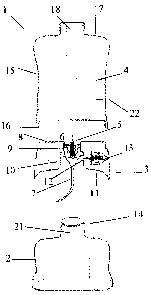
FiG. 1- Sectional view of the packaging according to
the present invention in exploded condition.
FIG. 2 - Sectional view with the lower recipient
distinguished from the packaging built according to the present
invention.
F1G. 3 - Sectional view of the packaging built
CA 02565399 2006-10-25
WO 2005/105611 PCT/BR2005/000064
according to the present invention.
FIG. 4 - Sectional view of the packaging built
according to the present invention in exploded condition with
recharge refill.
5 FIG. 5 - Sectional view with the lower recipient
distinguished from the packaging built according to the present
invention with recharge refill.
FIG. 6 - Sectional view of the packaging built
according to the present invention with recharging refili.
io As we conclude from the drawings of the packaging (1) it is built in
three independent sectors. A lower recipient (2) a ring shaped
central valved segment (3) and a superior mixing and dosage
chamber (4).
The three parts (2) (3) (4) when joined together form a flask (1) of
proper dimensions for domestic handling of products such as
shampoos, liquid soap, laundry softener. The variation of the final
form and volume of the packaging are included in the scope of the
present patent.
The ring shaped segment of the packaging (3) presents a central
~o cylinder opening (5) of ejection where there is a one-way valve (6)
placed in upward direction, for use with liquids and semi liquids,
that contains in its inferior part a flexible collecting tube (7) that has
I-o be long enough to reach the bottom of the inferior recipient (2).
The ring shaped segment (3) is screwed in its external upper
extremity (27) and a closing surface (8) with a central round
opening (5) that limits an internal cylindrical region (9) that must be
big enough to hold a valve (6). Below the cylindrical part (9) where
the valve is placed (6) the ring shaped segment presents a wider
CA 02565399 2006-10-25
WO 2005/105611 PCT/BR2005/000064
6
cylindrical extension (10) from which an inferior closing surface
extends (11).
This wider cylindrical extension has a lateral orifice for air input
i12). This air comes from a duct placed horizontally inside the ring
shaped segment (3) where there is an one-way air valve (13) that
interacts with the exterior environment.
T his cylindrical extension (10) is screwed and receives the
bottleneck (21) of the bottom recipient (2) externally screwed linking
the valved ring shaped segment to the bottom recipient (2).
io The bottleneck (21) of the bottom recipient (2) has a small lateral
opening (14) that when linked to the bottom recipient (2) with the
ring shaped segment (3) must be disposed in the direction of the aib
opening (12) to allow the input of air into the bottom recipient to
provide the internal pressure balance and the return to its original
ls form after the expelling of the dose of the product by means of
pressing and the deformation of the walls of the recipient that are
built in a flexible or semi flexible material.
The small lateral opening or orifice (14) of the bottleneck (21) of the
bottom recipient (2) may have the configuration of a sma{i
2O horizontal slot to facilitate the relative positioning of the bottom
recipient (2) with the ring shaped (3) segment.
The position of the small lateral opening (14) is indicated through a
mark in the body of the recipient below the connection making the
alignment with the orifice of the cylindrical region (10) with the
25 lateral opening of the bottleneck easier (21).
The upper dosage and mixture chamber (4) is built by a tubular
body (15) with a lower closing wall (25) dislocated from the lower
extreme of the wall of the tubular body (15) presenting a central
CA 02565399 2006-10-25
WO 2005/105611 PCT/BR2005/000064
7
circular opening (26) for the passage of the liquid valve (6). The
lower extreme of the tubular body wall has an internal screw (16) to
link to the ring shaped segment (3).
The upper dosage and mixture chamber (4) presents in its upper
extremity a closing wall (17) with a discharge opening (18) that has
a closing lid (not shown in the figure).
T he discharge opening (18) illustrated in an overview as a
bottleneck may take any other form suitable for the end use it is
destined as for example dosage pump for liquid soap, articulated
io nozzle for shampoos, screwed lid for laundry softener etc.
The chamber (4) shows a certain transparence and one or more
external marks of amount of concentrated product volume (22)
;doses).
in the construction shown in figures 1, 2 and 3 the concentrated
content is commercialized in the complete packaging (1) or in a
recipient that corresponds to the bottom recipient (2) which will also
be a refill.
In the figures 4, 5, and 6, the construction shows that the
concentrated product is in a sachet (19) or cushion, which is
2o replaceable when the product is over. In this case it is forecasted
that in the place of the flexible collecting tube (7) a rigid one (20) is
adopted. When the ring shaped segment (3) is joined to the bottom
recipient it perforates the sachet and when the bottom recipient is
pressed the concentrated product is impelled through the rigid
collecting tube (20) through the one-way valve (6) into the dosage
and mixing chamber.
In this conception, the bottom recipient (2) is shown in the form of a
cup to hold the sachet (19) with an extension of the external
CA 02565399 2006-10-25
WO 2005/105611 PCT/BR2005/000064
8
surface (23) screwed in its upper extremity to be screwed in the
valved ring shaped segment (3) that presents in its bottom
extremity an extension in the internal surface (24) screwed.
After placing or replacing the sachet (19) inside the bottom recipient
in the form of cup (2), the rigid collecting tube (20) is placed at the
center of the sachet (19) perforating it and then the bottom recipient
(2) is screwed to the ring shaped segment (3).
The internal pressure is balanced by the air admitted by the air
valve (13) that connects the bottom recipient defined internal space
io with the environment.
The pressure on the walls of the bottom recipient (2) closes the air
valve (13) and the pressure is transferred to the liquid that is then
admitted to the collecting tube (7) (20) that through the one-way
liquid valve (6) moves into the dosage and mixture (4) or dilution
chamber.
When the amount of concentrated product fills up the chamber (4)
the pressure on the walls is released and the one-way air valve
allows the air into the bottom recipient (2).
The dose of the concentrated product that is in the upper chamber
(4) is diluted there and used until it is over when a new process of
dosage and dilution is performed.