Note: Descriptions are shown in the official language in which they were submitted.
CA 02566314 2006-11-01
WO 2005/115886 PCT/EP2005/004106
Unit and Method for Conveying Workpieces
Along a Processing Run
Technical Field
The invention relates to a unit for conveying workpieces on a
processing run.
Along such a processing run, there is located at least one,
however, mostly several of successive processing stations into
which said workpieces are introduced for surface treatment.
Such a processing station may, for example, be a dipping bath
containing a processing liquid, the expression processing
station may, however, also be understood to be any other kind
of cabin or basin in which processing of the workpiece takes
place. Such treatment may, for example, also encompass a
washing process. Other examples of processing are dipping-
phosphatizing, pre-treatment for immersion-painting, powder-
coating, wet-painting or the like.
Prior Art
Units known so far for the surface treatment of workpieces,
such as car bodies in dipping baths or processing cabins, are
divided into continuously conveying units and non-continuously
conveying units.
In continuously conveying units, the car bodies are conveyed
in a conveying direction along the processing run using a
chain drive and are at the same time lowered into the dipping
baths, conveyed through said dipping baths and lifted out of
CA 02566314 2006-11-01
2
said dipping baths again. A continuously conveying unit for
the surface treatment of car bodies is described in DE-A-196
41 048. In said unit the car bodies are held by mounts which
are guided, at a fixed distance from each other, for example
by means of a revolving chain, above the processing basins
along a guiding way. The mounts are turned for introducing or
removing the car bodies into and from the basins respectively.
The corresponding rotating axes of the mounts are thereby
oriented in parallel with the conveying direction. There is
also the possibility to fold the mounts by 90 for return in
order to save space.
There are also known in the art non-continuously conveying
units which are referred to as cycle units. In cycle units,
the car bodies are transported on carriers over the dipping
basins, are stopped there and dipped into the processing bath
using lifting devices, for example lifting units or rotating
means, and are lifted or rotated thereout after lapse of the
process time. Examples of such a unit are described in DE-C-43
04 145 and DE-U-200 22 634 as well as PCT/EP 2002/001782.
In some of the continuously and non-continuously conveying
units known so far, the introduction of the car bodies into
the dipping basins and the removal of the car bodies from the
dipping bath is realized by means of rotation of the car
bodies which are eccentrically arranged on the car body
carrier around a rotating axis which is located transversely
to the conveying direction. The movement carried out by the
workpiece through the dipping bath is thereby completely
different from the one in the unit of DE-A-196 41 048
described above, in which the rotating axis runs parallel to
the conveying direction. The car body carriers are then
supported, for example, on two guiding ways located on the
left and the right of the dipping basins. The car body
carriers can then be fixed for conveying on two revolving
chains which are driven or diverted via chain wheels with a
horizontal rotating axis and which are arranged at the start
and the end of the processing run. At the end of the
CA 02566314 2006-11-01
3
processing run the unloaded car body carriers are diverted via
the chain wheels and returned underneath the dipping bath.
The choice between a continuously conveying and a non-
continuously conveying unit needs to be made in consideration
of the specific advantages and disadvantages of both basic
concepts. The continuously conveying units are more reliable
since the units run using few driving motors, while the
individually-cycled carriers of cycle units show an increased
likelihood of breakdowns due to several individually
controlled motors. The maximum capacity of workpieces per time
unit is also greater in continuous units than is the case in
cycle units. The advantage of cycle units, on the other hand,
lies in the high degree of flexibility of workpiece processing
due to the possibility to individually drive the individual
carriers.
The present invention is mainly directed at continuously
conveying units it, can, however, also easily be applied in
non-continuously conveying units.
Illustration of the Invention
The present invention is based on the object to create a unit
as well as a method for conveying a workpiece along a
processing run by means of which return of the unloaded
workpiece carriers can be effected in a space-saving manner.
This object is solved by means of a unit according to patent
claim 1.
Accordingly, the unit according to the invention comprises at
least one transport car for conveying a workpiece along a
processing run, said transport car is movable along the
processing run in a conveying direction. A rotating shaft is
supported on the transport car close to a first of its ends
and at right angles to the conveying direction to rotate
around its axis. A mounting for the workpiece which is to be
CA 02566314 2006-11-01
4
processed is provided on the rotating shaft. According to the
invention, the rotating shaft is only supported close to its
first end on the transport car and is thus drivable in the
conveying direction, whereas its second, free end is moved
along passively in the conveying direction.
Accordingly, only one end of the rotating shaft is connected
to the transport car. Thus, only one transport car is needed
for conveying the workpiece at the rotating shaft in the
conveying direction, said transport car can move along a
single guiding way and may be driven by means of a single
conveyer chain or a single conveying belt.
Driving and diverting wheels at the start and the end of the
processing run can thus be implemented either with a
horizontal or with a vertical axis.
The arrangement of the rotating shaft according to the
invention, wherein the second end remains free also
facilitates, in particular, pivoting the unloaded rotating
shaft prior to or during diversion from the horizontal into
the vertical position as well as a space-saving return
adjacent to the processing run. These and other advantageous
features of the unit according to the invention are described
in dependent claims 2 to 17.
The rotating shaft is preferably arranged in such a manner
that it is at least in part pivotable in a plane running at
right angles to the conveying direction. In this regard, the
transport car may be arranged to be pivotable in said plane
together with the entire rotating shaft, and/or the rotating
shaft may include a folding mechanism, by means of which the
second end of the rotating shaft is pivotable in said plane.
The latter-mentioned variant facilitates pivoting the shaft
with comparably small constructional complexity.
The second end of the rotating shaft can be provided with a
non-driven support member which may run on a supporting
CA 02566314 2010-04-08
surface, for example on an already provided rim of a dipping
basin. In the case of such a support of the free end of the
shaft, the loads acting on the workpiece carrier are reduced.
The rotating movement of the rotating shaft around its axis
may be suitably coupled, using a rotation drive, with the
movement of the transport car in the conveying direction; this
brings about the advantage that no separate drive is required
for the creation of this rotating movement and the energy
required is reduced. The rotating drive may thereby for
example be a roller lever. Variants are also possible with a
gear which facilitates certain adaptation of the rotating
movement of the rotating shaft.
There may, however, also be provided a separate rotating drive,
for example, an electric drive, for creating the rotation of
the rotating shaft around its axis. Said rotation may then
occur completely independently of the movement of the
transport car in the conveying direction.
The unit according to the invention is preferably provided
with means for compensating for the torque created at the
workpiece which is connected to the rotating shaft. There may,
for example, be provided a counter-weight on the first end of
the rotating shaft for compensating for the torque, preferably
using a carrier, such that its distance from the rotating axis
is variable. It is also possible to use a lever-spring
mechanism for the compensation of the torque.
The above-mentioned object is, on the other hand, also solved
by a method for conveying a workpiece along a processing run
as according to claim 18.
Accordingly, a transport car is first driven into a starting
position. There, a workpiece which is to be processed is fixed
on a rotating shaft which is rotatably supported in the area
of a first of its ends on the transport car. Said transport
car is now moved along a processing run in a conveying
CA 02566314 2006-11-01
6
direction, with the rotating shaft being oriented at right
angles to said conveying direction. In a disposal position the
workpiece is detached from the rotating shaft following
processing. Following thereafter, according to the invention,
the rotating shaft is pivoted in a plane running at right
angles to the conveying direction and the transport car is
returned with the rotating shaft to the starting position.
The rotating shaft can thus be pivoted into a space-saving
orientation for its return.
Preferred developments of the method according to the
invention are described in the pertinent dependent claims.
The transport car can be diverted during pivoting or following
pivoting on a return run, can be returned there and again
diverted in order to reach the starting position and can be
pivoted into its original position. This sequence facilitates
returning the transport car with the rotating shaft in a
particularly space-saving manner.
If a partial area of the rotating shaft which includes the
second end of the rotating shaft is pivoted in said plane,
said partial area of the rotating shaft may be diverted during
pivoting or following pivoting to a return run, it may be
oriented parallel with the conveying direction for return, and
may be diverted again to reach the starting position and can
be pivoted into its original position. The orientation of the
shaft in parallel with the conveying direction during return
results in by far less space being required perpendicular to
the conveying direction.
Brief Description of the Drawings
Fig. 1 is a schematic overall view of a unit according
to the invention for transporting workpieces,
CA 02566314 2006-11-01
7
Fig. 2 is a perspective view of a first embodiment of
a transport car which is part of the unit
according to the invention,
Fig. 3a shows the transport car of Fig. 2 in
combination with a rotating shaft and a roller
lever,
Fig. 3b shows the transport car of Fig. 2 in
combination with a rotating shaft and an
electric drive,
Fig. 4a shows a first possibility of creating the
rotation of the rotating shaft in a front view,
Fig. 4b is the pertinent side view,
Fig. 5a shows a second possibility of creating the
rotation of the rotating shaft in a front view,
Fig. 5b is the pertinent side view,
Figs. 6a to e are different views of a 450 diversion
mechanism,
Figs. 7a to d are different views of a 900 diversion
mechanism,
Fig. 8a is a side view of a unit according to the
invention comprising a foldable rotating shaft,
Fig. 8b is the pertinent top view,
Fig. 8c is the same view as is shown in Fig. 8a, but
shows the rotating shaft in the folded state,
and
CA 02566314 2010-04-08
8
Fig. 9 shows different embodiments of a mechanism' for
torque compensation.
Detailed Description of Preferred Embodiments
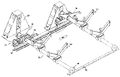
A schematic overall view of a unit according to the invention
is shown in Fig. 1.
Using this unit, workpieces can be transported through a
processing station. In particular, a unit of this type may
serve to guide car body parts through a dipping bath in order
to varnish the same. For this purpose, the unit comprises a
plurality of workpiece carriers, two of which are shown in Fig. 1,
and which are each formed by a transport car 10 and a rotating
shaft 20 as essential parts.
Rotating shafts 20, in turn, each show mounts 40, on which the
car body parts which are to be varnished can be fixed directly
or using so-called skids. Rotating shafts 20 are rotatably
supported on transport car 10 and move together with transport
car 10 in a conveying direction characterized by "FR" along a
guiding way 70. For this purpose, transport cars 10 are driven,
for example using a conveying chain, a rope or a belt. A
dipping bath (not shown), into which the car body parts which
are fixed to mounts 40 are to be dipped for varnishing, is
located adjacent to guiding way 70 and below the plane, in
which rotating shafts 20 are moving; rotating shafts 20 are
thus guided over the dipping bath using transport cars 10.
In order to now dip the car body parts into the dipping bath
while rotating shafts 20 are moved over the dipping bath,
there is provided a mechanism by means of which rotating shaft
20 can be put into rotating movement during the translational
movement of transport car 10 and rotating shaft 20 along the
guiding way 70. In the embodiment shown in Fig. 1, this
mechanism is a roller lever 30. Said roller lever is connected
or can temporarily be connected to rotating shaft 20 in a
rotationally stiff manner and causes rotating shaft 20 to
CA 02566314 2006-11-01
9
rotate as soon as the same is in a suitable position above the
dipping bath so as for the car body part on mounts 40 which is
to be varnished to be rotated into the dipping bath while, at
the same time, being drawn through the dipping bath since
transport car 10 continuously moves further along the guiding
way 70.
It is, as a matter of course, also possible to provide a
discontinuous operation of this unit in which, for example,
the movement of transport car 10 along guiding way 70 is
interrupted for the car body part to be dipped into the
dipping bath. This may be desirable in the case of certain
geometries of the car body parts or certain ancillary
conditions of the varnishing process. The choice between a
continuous and a discontinuous working manner is made by the
person skilled in the art taking into account all these
circumstances.
Guiding way 70 may in any case form an endless loop. A certain
position of this loop is a starting position where the car
body part is fixed, with or without interposition of a skid,
on mounts 40 of rotating shaft 20. Following thereafter, it is
conveyed along a processing run of guiding way 70 through the
dipping bath, and is detached from mounts 40 at a disposal
position and removed for further processing. Transport car 10
with unloaded rotating shaft 20 is then returned along a
return run of endless guiding way 70 into the starting
position. The return run of guiding way 70 may thereby extend
adjacent to the processing run and may be connected thereto
via diversion areas.
It now also becomes particularly clear from Fig. 1 that the
unit according to the invention requires only a single guiding
way 70 and, according to the invention, rotating shaft 20 is
supported on transport car 10 only on its first end and is
driven in the conveying direction FR in this manner, whereas
its second, free end is passively moved along. This is carried
out in a manner contrary to conventional units, in which both
CA 02566314 2006-11-01
ends of the rotating shaft are guided along a guiding way
respectively. In the illustrated embodiment, this second, free
end of rotating shaft 20 is merely provided with a non-driven
support roller 80 which rolls on a support surface 90.
Said support surface 90 may be formed for example by the
anyway provided rim of the dipping bath. Support roller 80 or
a corresponding support element is, however, not necessarily
required; in a suitable design of the remaining constructive
elements, the free end of rotating shaft 20 is also capable of
free spatial movement.
During the rotation of the workpiece into and out of the
dipping bath great torques are created on rotating shaft 20
which need to be supported via rotating shaft 20 and transport
car 10 onto guiding way 70 and which create additional shear
forces during inward rotation and outward rotation. The entire
unit is thereby exposed to strong and continuously fluctuating
loads.
Said torques can be compensated in various ways. In the
embodiment of Fig. 1, a counter-weight 50 is provided for this
purpose on a carrier 60 which, in turn, is supported on the
end of rotating shaft 20 which faces away from mounts 40.
Arranging counter-weight 50 at a certain distance from the
rotating axis of rotating shaft 20 compensates at least in
part for the torque of the workpiece.
In this regard, the distance of counter-weight 50 to said
rotating axis may be variable. This can also be taken from
Fig. 1. In the workpiece carrier shown on the right-hand side,
the counter-weight is at a relatively large distance from the
rotating axis of rotating shaft 20 and could thus balance the
torque of a workpiece fixed to pertinent mounts 40. In the
workpiece carrier shown on the left-hand side, counter-
weight 50 is, on the other hand, shifted into the axis of
rotating shaft 20 and thus does not exert a compensation
torque.
CA 02566314 2006-11-01
11
The last-mentioned position is adopted in particular when the
workpiece carrier is conveyed along guiding way 70. Counter-
weight 50 should then be neutralized. This can alternatively
also be effected by decoupling counter-weight 50 from the
rotating axis or by decoupling roller lever 30 from the
rotating axis.
The compensation of the torques significantly reduces the
forces acting upon the conveying chain and the fluctuations in
load are reduced. The solutions for the compensation of the
torques thus support at the same time the restriction to a
single chain, rope or belt line.
Fig. 2a shows a first embodiment of a transport car 10 which
can be used in the unit according to the invention. It is also
implied in Fig. 2a that conveying car 10 is movable along
guiding way 17 using a conveying chain 15 or a rope 151.
Reception 25 serves to support rotating shaft 20.
Fig. 3a shows the transport car 10 illustrated in Fig. 2 in
combination with a rotating shaft 20. There is also shown the
roller lever 30 already described with reference to Fig. 1,
the movement of which causes rotating shaft 20 to rotate
during the conveying movement of transport car 10 along a
guiding way.
As an alternative, rotating shaft 20 may also be driven
independently of the conveying movement, for example using an
electric auxiliary power, and may also have corresponding
mechanical and/or hydraulic or pneumatic transmission elements.
Said rotating mechanism may be arbitrarily switched using a
corresponding control and may be changed with regard to a
rotating direction and rotating speed. This is illustrated in
Fig. 3b: Instead of roller lever 30, in this case there is
provided an electric drive 35 which creates the rotating
movement of rotating shaft 20 independently of the conveying
direction.
CA 02566314 2006-11-01
12
The rotating movement of rotating shaft 20 may also be
facilitated, instead of using roller lever 30, in a flexible
manner by means of the rotating mechanisms illustrated in
Figs 4a, 4b and 5a, 5b and described below, namely using a
spur gear unit (Figs. 4a, 4b) or a chain drive (5a, 5b)
arranged on transport car 10 and using a rack and pinion gear
pair (120, 130) via the conveying movement of transport car 10
initiated by the chain.
The rotating speed may thereby be modified by means of a gear
box control or by changing the diameters of the pinion. The
rotating direction may in particular also be changed using a
gear box control or by changing the arrangement of the rack
with regard to the pinion (above - below). Stopping positions
of the rotating shaft can be realized by means of decoupling
the drive or by interrupting rack 120. Reference number 100 in
Figs. 4a and 5a designates a disc brake, 110 designates a
ratch coupling.
The advantage of this gear lies in that the rotating speed is
not necessarily connected in a 1:1 manner to the conveying
speed of transport car 10.
All these possibilities for creating the rotation of rotating
shaft 20 are known as such and are thus not described here in
any more detail.
As has already been described, the unit according to the
invention is characterized in that only one end of rotating
shaft 20 is supported on transport car 10, the other end is
free. This results in a number of advantages. It is in
particular possible to pivot rotating shaft 20 due to its free
end in the unloaded state also and in particular for its
return in various manners and therefore the return can be
carried out in a particularly space-saving manner.
For this purpose, on the one hand, the entire workpiece
carrier which consists of transport car 10 and rotating
CA 02566314 2006-11-01
13
shaft 20 may be pivoted around a joint point arranged in the
coupling area between the chain and the workpiece carrier,
either using a separate pivoting mechanism or using rollers
which run in guiding ways formed in a spiral manner and which
are attached on the car body carrier. Fig. 6 shows such a
separate pivoting mechanism: The entire transport car 10 is
pivoted together with a pivoting mount 200 vis-a-vis
stationary circular arc ways 210. In the embodiment of Fig. 6,
pivoting is possible by 45 . In this regard, Fig. 6a is a side
view, Fig. 6b is a rear view, Fig. 6c is a front view, Fig. 6d
is a perspective view and Fig. 6e is a top view.
The pivoting mechanism of Fig. 7 is similar to the one shown
in Fig. 6. Fig. 7a is a side view, Fig. 7b is a rear view,
Fig. 7c is a perspective view and Fig. 7d is a top view. The
pivoting mechanism of Fig. 7, however, facilitates pivoting by
90 . This is carried out in the following manner: After the
workpiece has been conveyed on mounts 40 through the dipping
bath and has been detached from said mounts 40 at the disposal
station, transport car 10 is driven together with empty
rotating shaft 20 into the pivoting station shown in Fig. 7
and is pivoted there by 90 together with pivoting mount 200
so as for rotating shaft 20 to face downwards. With this
orientation of rotating shaft 20, transport car 10 can then be
moved through a diversion area (not shown) of the guiding way
to the return run of the guiding way. Rotating shaft 20
remains in this downwardly-directed position during the return
of transport car 10 so that significantly less space is
required than would be the case if the shaft was returned in
its horizontal orientation - as is the case in conventional
units in which the shaft is supported at both ends and is thus
always transported in a horizontal manner. Before fixing a new
car body part to mounts 40 in the starting position, transport
car 10 is again pivoted with rotating shaft 20 in a further
pivoting station so that rotating shaft 20 adopts its
horizontal position again.
CA 02566314 2006-11-01
14
An alternative to the pivoting stations lies in designing
rotating shaft 20 to be foldable itself. This is shown in
Fig. 8. Figs. 8a and 8b show rotating shaft 20 in its
horizontal position. Following unlocking of a locking
mechanism 300, the shaft can be unfolded downwardly in a
pivoting range 22. The position unfolded downwardly by 900 is
shown in Fig. 8c. In contrast with the embodiment of Figs. 6
and 7, here not the entire transport car 10 as well as
rotating shaft 20 are pivoted, but only the largest part of
rotating shaft 20 which is arranged on the right-hand side in
Fig. 8. Thus, rotating shaft 20 can also be brought in a
vertical position which is directed downwardly for diversion
and return thereof along the guiding way. Folding and
unfolding of rotating shaft 20 at mount joint 22 is realized
by forming a cam track, the position of the mount joint and
the weight of the rotating shaft part itself without any
external drive.
Moreover, this foldable design of rotating shaft 20 also
facilitates pivoting rotating shaft 20 on the return run from
the vertically downwardly directing orientation into an
orientation in parallel with the return run which further
reduces the space required for rotating shaft 20 on the return
run. Here the pivoting step is also facilitated either by
means of a separate pivoting mechanism' or by means of rollers
which run in spirally formed guiding ways and which are fixed
to the workpiece carrier or, however, by designing a
corresponding rotating lever guiding way which realizes the
pivoting step of the rotating shaft.
It will now be clarified, referring to Fig. 9, that the torque
of the workpiece around the rotating axis of rotating shaft 20
can be compensated, at least in part, by means of a lever-
spring mechanism instead of a counter-weight 50 in which
springs are tensioned during the rotation of the workpiece
into the dipping bath and thus counteract the torque of the
workpiece. The torque required for rotating the workpiece
CA 02566314 2006-11-01
outwardly is then correspondingly reduced by the relaxing
springs.
If the workpiece carrier is once conveyed through the
processing run in an unloaded state, the effect of the lever-
spring mechanism as well as the counter-weight described above
need to be neutralized. This can be realized as follows:
decoupling the lever-spring mechanism from the rotating
shaft of the workpiece carrier,
- decoupling the elements of the rotating mechanism' (e.g.
during rotation by means of roller levers running in
guiding ways) vis-a-vis the rotating axis of the workpiece
carrier, or
switching off the rotating mechanism.
Figs. 9a) and b) show a lever-spring mechanism with a curve
disc, Figs. 9 c) and d) with eccentrically designed springs,
and Figs. 9 e) and f) with a batch crank or a crank loop. In
this regard, M is the rotating axis of the rotating shaft and
S is the point of application of the weight force of the
workpiece at the rotating shaft.