Note: Descriptions are shown in the official language in which they were submitted.
CA 02566520 2006-11-14
WO 2005/111302 PCT/EP2005/004787
Forming Sieve for the Wet End Section of a Paaer Machine
The present invention relates to a single- or multiple-layered forming sieve
for the wet end
section of a paper machine, according to the pre-characterizing section of
Claim 1.
Background to the Invention
In the conventional Fourdrinier paper-manufacturing method, an aqueous pulp or
suspension of cellulose fibres (known as "paper stock") is placed onto the
upper surface
of a so-called endless web made of wire and/or a synthetic material. This wire
web acts,as
a filter, which causes the cellulose fibres to be separated from the aqueous
medium and
form a so-called wet-paper sheet. During formation of this wet-paper sheet,
the forming
sieve acts as a filter which separates the aqueous medium from the cellulose
fibres, as
the aqueous medium passes through the openings in the sieve.
To accelerate the removal of the water, the filtering process is very often
carried out with
the additional action of a vacuum applied to the underside of the sieve, i.e.
on the
machine side. Once the paper sheet has left the forming end section it is
transferred to a
press section of the paper machine, at this point it is guided through the gap
between a
pair, or several pairs, of pressure rollers, over which is stretched another
fabric: a so-
called "press felt". The pressure of the rollers acting on the paper sheet
removes
additional moisture, and is frequently enhanced by the presence of a "mat"
layer within the
press felt. After passing through the pressing section, the paper is sent to a
drying section
of the machine for further removal of moisture. After drying, the paper is
ready for any
secondary processing which may be undertaken and finally packing.
CA 02566520 2006-11-14
WO 2005/111302 PCT/EP2005/004787
The sieves used in paper-machines are made available as endless webs, and are
manufactured by one of two methods. According to the first method, the free
ends of
individual flat woven webs are connected together by a procedure known as
"splicing",
and in so doing the endless web is formed. In flat-woven paper-machine sieves
formed in
this way, the warp threads run in the machine direction, and the filling or
weft threads run
in the cross direction. According to the second production technique, the
paper-machine
sieves are directly fashioned in the form of a continuous strip, by the so-
called endless-
web method. In this method, the warp threads run in the cross direction of the
machine,
with the weft threads in the machine direction. Within the relevant
literature, abbreviations
for these terms are commonly used, with MD standing for "machine direction"
and CMD
for "cross machine direction".
Within the wet end section of a paper machine, it is extremely important to
maintain the
cellulose fibres in the suspension on the paper side of the sieve, and to
avoid markings
within the forming sheet. These markings can occur when individual cellulose
fibres are
oriented within the paper sheet, such that their ends coincide with
interstices between the
individual threads of the sieve. In general, an attempt is made to solve this
problem by
providing a permeable sieve structure which is possessed of a coplanar
surface, and
which further allows the paper fibres to form a bridge over adjacent threads
in the fabric
and not penetrate into the interstices between them. As used herein,
"coplanar" means
that the uppermost parts of the threads, those which define the paper-forming
surface of
the sieve and are termed floats or knuckles respectively, lie at substantially
the same
height, so as to present a surface which is substantially "planar". Fine
paper, such as that
used for high-quality printing, carbonization, cigarettes, electrical
capacitors, and other
papers of similar quality, has previously been produced on very finely woven
sieves, as
these present the flattest surfaces.
In order to make the surface of the cloth as close to planar as possible,
particularly in the
case of forming sieves, the surfaces are very often ground down with fine-
grain emery
paper. Such grinding is intended to improve the topography of the paper, and
lead to a
better final surface. Unfortunately, by grinding the surface in this way, the
thread floats
and knuckles of a sieve become damaged; this can be seen in Figs. 3 and 4 when
compared with Figs. 1 and 2. Fig. 1 shows a section of a forming sieve which
has not
been processed, that is the floats or knuckles have not been ground with emery
paper.
Fig. 2 shows a section of the sieve according to Fig. 1, but under greater
magnification.
Figs. 3 and 4 correspond to the photographs shown in Figs. 1 and 2, with the
exception
2
CA 02566520 2006-11-14
WO 2005/111302 PCT/EP2005/004787
that in the sieve according to Figs. 3 and 4, the topography of the paper has
been evened
out by grinding down the floats or knuckles. Whilst this particular levelling
procedure does
not reduce the interior volume of the sieve, the thickness is slightly
reduced. This has
further disadvantageous side effects, in that the stability of the sieve is
adversely affected
as a result: primarily, the loss of material entails a lower sieve stiffness.
Furthermore, it
has been found that as a result of this mechanical intervention, the sieve
suffers from
increased abrasion and hence a shorter operating life. In the case of threads
with small
diameters, e.g. 0.11 mm to 0.13 mm, the grinding process reduces the cross
section of
the threads by 30-40%. Such severe mechanical alteration of the threads, and
hence of
the sieve, can be seen as the root cause of the reduction in sieve stiffness.
This is a
further problem, as current trends in the paper industry are moving
increasingly towards
even thinner sieves with. correspondingly thinner thread diameters. With this
progression,
limits are being placed on the mechanical alterations possible in order to
produce
coplanar sieve surfaces.
To further elucidate the state of the art as shown in Figs. 1 to 4, reference
is also made to
Figs. 5 and 6 as well as 7 and B. Fig. 5 shows the contact surface of a sieve
according to
Figs. 1 and 2, the untreated sieve, wherein about 30% of the total surface
comprises the
contact surface of the sieve. Fig. 6 shows the "standard" shape of floats and
knuckles
present in an untreated sieve, according to Figs. I and 2. Figs. 7 and 8
detail the structure
of a ground-down sieve, wherein removal of 0.02 mm from the protruding floats
and
knuckles, increases the contact surface of the sieve to about 34%. The float
or knuckle
shape after grinding is shown in Fig. 8.
An objective of the current invention, is the preparation of sieves that
present a highly
coplanar surface, at least on the paper side, but preferably on both the paper
and
machine sides. This is to be achieved, even for sieves that are considerably
thinner than
those disclosed in the art, and have correspondingly reduced thread diameters.
In light of
the various problems presented above, this objective is to be achieved in
particular for so-
called forming sieves, i.e. sieves intended for use in the wet end section of
a paper
machine.
Summary of the Invention
The above objective is achieved by the characterizing features given in Claim
1, with
advantageous further developments and embodiments being described in the
subordinate
claims.
3
CA 02566520 2006-11-14
WO 2005/111302 PCT/EP2005/004787
A single- or multilayered forming sieve for the wet end-section of a paper
machine with
upper machine-direction, MD, and cross-machine-direction, CMD, threads facing
the
paper side, and lower MD and CMD threads facing the machine is disclosed. The
forming
sieve having, at least the paper-side thread inflection regions reshaped by
means of one
or a combination of temperature, pressure and/or moisture. A method for
achieving such
reshaping is given in claim 15, wherein rollers are used for the application
of the pressure
and/or temperature.
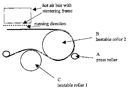
Detailed Description of One Way of Implementing the Invention.
The production of sieves for paper machines in the current invention, is based
around a
system of compacting or "hot calendering" the fabric making up the sieve, in a
press
arrangement. This action is undertaken at least at one of, or a combination
of: an elevated
pressure, an elevated temperature and/or at an elevated moisture level, for a
specific
time; this time being a result of the chosen threads, and the desired
properties of the
finished product.
When fabrics which are possessed of an endless structure are employed, that is
there are
no ends making up a joining seam, they are usually configured with two warp
thread
systems. The calendering, or compacting, of this fabric is accomplished
between at least
two rollers, as can be seen in the examples shown in Fig. 9. Whilst three
possible
structures are shown in this figure detailing apparatus for compacting the
fabric, these are
not to be considered as limiting the invention in any way, and are shown as
examples
only.
Fig. 9b shows the simplest structure, in that only two rollers are provided,
between which
the fabric is compacted. In order to increase the usable area of the heated
roller, which in
turn means that the fabric will be in contact with the heat for a greater
length of time, a
third roller c can be provided as shown in figs. 9 a and Fig. 9 c.
Furthermore, these
additional rollers can be heatable if further heat application to the fabric
is required in the
process. The specific number and relative positions of the fabric, can be
chosen
depending upon the precise requirements of the fabric and the final desired
structure at
the surface thereof.
To compact or calender the fabric of the sieve, requires the provision of two
rollers which
can be brought together and a desired pressure applied between them. These are
shown
4
CA 02566520 2006-11-14
WO 2005/111302 PCT/EP2005/004787
by reference numerals A and B in Fig. 9. Here, the sieve fabric passes between
the gap
provided between the two rollers, and the required pressure is applied; this
pressure,
commonly lies between 10 and 40 kPa. The roller A, called a press roller, is
formed of a
plurality of segments which run along the width of the sieve fabric and can be
tuned to
provide different pressures across the sieve. This plurality of press rollers,
allows the final
sieve to be formed with a specific and selectable cross sectional profile.
As shown in the examples of Fig. 9, at least one of the rollers can be heated,
with the
temperature lying somewhere between 100-190 C, although it has been found that
most
processes are undertaken in the range 140-170 C. The specific temperature
chosen will
depend upon the thread within the fabric, and the final desired structure to
the surface of
the sieve. It is possible to heat one or both sides of the fabric as it is
being compacted,
and it is further possible to adjust the temperature profile along the width
and length of the
fabric during such processing. This will result in a fabric for which, at each
point along its
length and width, the specific temperature and pressure can be individually
tailored to suit
the desired final requirements of the sieve in a targeted manner.
For fabrics that are possessed of two ends, which are joined together via a
seam to form
the endless structure, the compacting process is a little different.
Initially, it is necessary to
specifically control the pressures which are applied to the starting and end
points of the
fabric. This is achieved by providing a ramp control to the applied pressure,
wherein the
machine is aware of the start and end points to the fabric, and thus a process
is achieved
which suffers from no transitions. All other processing of the "fabric follows
the method
detailed above for the preformed endless fabric.
The specific tension applied to the fabric during the calendering process,
whether
preformed or one with a seam, is dependent upon the individual fabric design.
During the
compacting process the fabric will change its length by up to 1.5%, a fact
which requires
taking into account at the fabric forming stage and prior to the calendering
process.
Furthermore, changes to the width of the fabric, which lie in the range 0-3%
are generally
monitored, and compensated for with simultaneous thermal treatment of the
fabric.
As shown in Fig. 9c, an additional drying unit can be provided which applies
heat to the
fabric after the compacting process. This is shown in the figure as being
provided by a
heat box with a tenter for drying the fabric over. Clearly, other options
exist for this drying
stage, and are not limited to that disclosed in the drawings.
5
CA 02566520 2006-11-14
WO 2005/111302 PCT/EP2005/004787
The threads which form the fabric of the sieves can comprise or contain a
polymer such
as one, or a combination of: a polyester, a polyamide and/or a polyolefin.
Furthermore, the
calendering process as disclosed can readily be implemented on sieves which
have warp
threads present on the paper side with a diameter of between 0.09 and 0.20 mm,
and
machine-side warp threads having a diameter of between 0.15 and 0.30 mm. In
particular
the paper side threads are chosen with a diameter of 0.13mm and the machine-
side
threads with a diameter of about 0.18 mm. Additionally, the compressive
process can be
used on fabrics which are possessed of one or multiple layers.
As is shown in Figs. 10 and 11, the fabrics processed according to the current
invention,
have a substantially different structure to those processed with the
conventional grinding
techniques. The knuckles or floats of the interwoven threads, can be seen to
have a
compacted or flattened shape on the side facing the paper and/or the
papermaking
machine. The key difference here, however, is that the floats or knuckles are
not
mechanically damaged as they are when ground down; compare Fig. 11 with Fig.
4. In
addition to this, there is the further advantage that the calendered fabric
has no loss of
material, as Fig. 12 shows when compared with Fig. 8, which removes the
problems
associated with the sieves having a reduced stiffness.
The protruding knuckles or floats (10), can be seen in Figs. 10 and 11 to be
somewhat
flattened as a result of the compacting. This produces a relatively broad
"thread ellipse"
(11), which will run quietly within the paper machine as the fabric moves. As
a result of
this "thread ellipse", the width of the permanently flattened floats and
knuckles is greater
than the diameter of the remainder of the thread, which is best observed in
Fig. 11.
Indeed, it is preferable that the width of the flattened floats and knuckles
be about 5-15%
greater than the diameter of the remainder of the thread. Furthermore, the
height of the
flattened floats and knuckles is reduced by about 10-30%, and preferably is
approximately
20% less than the diameter of the remainder of the thread. That is, compacting
has
reduced the diameter by about 30-50%.
By compacting the threads in the fabric of the sieve at the float or knuckle
points, the
contact area of the sieve with the paper is increased by around 25-30%, when
compared
with an untreated sieve. This increase, leads to a sieve which is possessed of
a contact
area that is around 40-45% of the total area of the sieve. Such a measurement
can be
seen in Fig. 4, wherein a treated fabric is shown to have a contact area of 41
% of its total
surface area. Comparing Fig. 13 with both of Figs. 5 and 7, it is clear that
the current
invention shows greatly improved surface characteristics to the fabric over
the prior art
6
CA 02566520 2006-11-14
WO 2005/111302 PCT/EP2005/004787
techniques.
In addition to the increase in contact area for the calendered fabrics, these
sieves have
much smoother surfaces, when compared with untreated or ground fabrics, which
leads to
a much improved final paper topography. Moreover, a sieve which has
appropriately
compacted floats on the paper-machine side in addition to the paper side,
shows no
different weft knuckle heights when the fabric is loaded, as would be caused
by different
materials: this again improves the final paper surface as the knuckle heights
are reduced
on the paper machine side, other problems associated with new sieves running
on the
machine are dramatically. reduced. Of such problems, the most significant are
those
associated with the load which needs to be supported by the paper machine, and
the
starting up of the machine with a new sieve that has not been properly run-in.
In particular,
as a result of the broad, already formed, "thread ellipse", a sieve which is
adapted to the
machine is more rapidly obtained. In a papermaking machine a sieve which is
constructed
in accordance with the present invention, can start up more rapidly, it
requires less
subsequent adjustment and begins quiet running sooner, this is when compared
with
currently employed sieves.
Sieves with the float or knuckle shape in accordance with the invention,
exhibit no, or at
least greatly reduced, differences at the transition point between the seam
region and the
solid fabric. This leads to the sieves producing no marking on topographically
sensitive
kinds of paper. As a result of the slightly broader and flatter float shapes,
the sieve
exhibits higher stability and stiffness, because the interwoven threads are
displaced less
with respect to one another.
Clearly, the process of calendering a fabric leads to a permanent reduction in
the fabric
thickness as a result of the applied pressure. Depending upon the specific
treatment
applied, the thickness of the fabric can be reduced by between 1 and 20% of
the original.
In order to achieve this, the inflection heights and shapes of the individual
threads running
through the fabric are permanently altered. As there is no loss of material in
this
technique, merely a compressing, the weight per unit area of the fabric
remains constant.
In addition to the geometry of the threads within the sieve being altered
after calendering,
the internal volumes within the body of the fabric are permanently reduced.
Obviously,
when the fabrics are compressed and the thread geometry adjusted, it is
necessary for
the threads to move somewhere, and in this case there is a reduction in the
void size lying
between them as they are brought closer together. This reduction in cavity
size between
7
CA 02566520 2006-11-14
WO 2005/111302 PCT/EP2005/004787
the fibres has advantageous effects for the sieves as they run on the paper
making
machines. When the sieve is being used to hold the paper stock as the aqueous
medium
is being removed, it is possible for the cavities within the fabric to induce
turbulence as
they move. Such turbulence often produces the unwanted side effect of dragging
water
along with the cavities, as the sieve moves through the machine. Clearly, if
the water
remains within the sieve, the drying of the paper stock is adversely affected.
With the
reduction in cavity size associated with fabrics treated by the current
process, however,
the problems associated with turbulence and water logging are lessened. Once
again,
depending upon the specific fabric and treatment thereto, the cavities can be
reduced in
size by between 1 and 15%.
Further advantages result from the change in inflection points between the
threads in the
fabric, and from their altered geometry. With the increase in contact surface
area to the
fabric, there is a related increase to the level of friction between the
sieves and the paper
forming machine. This leads to a reduced delay in the movement of the fabric
when the
machinery is initially started, and further reductions in the transverse
motion whilst the
machine is running. Such improvements increases the efficiency of the paper
drying
process, whilst additionally requiring less adjustment to the belts with
prolonged usage.
Moreover, in the seam regions where present, the thread-thread friction is
increased with
this change in the inflection between the warp and weft threads, the result
being an
increase in the seam stability and strength.
Standard, that is un-calendered, sieves which are formed with a seam, will
tend to suffer
from inconsistencies in the thickness of the fabric between the regions of the
seam and
the main body of the fabric. This difference in surface properties can have
adverse effects
on the paper production, leading to marking of the page, and will also lead to
an increased
level of wear in this region. The compressing techniques of the current
invention,
however, alleviate these problems by giving a fabric which has a uniform
thickness along
its entire length. Furthermore, internal stresses and tensions on the fabric
threads which
result from these inconsistencies in the un-treated sieves, are substantially
equalised in
the fabric calendered in accordance with the present invention.
A final property of the fabric that is altered with the compressive treatment,
is that of the
permeability. It is assumed that it is the compaction of the fabric, giving
the reduction in
fabric thickness with corresponding changes to the void size and density,
which leads to
this difference. Dependent upon the initial fabric, and the treatment done
thereto, the
permeability can be reduced from between 0 and 30%, and this is usually taken
into
8
CA 02566520 2006-11-14
WO 2005/111302 PCT/EP2005/004787
consideration when the specific processing and fabric are being chosen.
While various features and embodiments of the invention are described above,
they can
readily be combined with each other resulting in further embodiments of the
invention.
9