Note: Descriptions are shown in the official language in which they were submitted.
CA 02566551 2006-10-31
-1-
TITLE: APPARATUS FOR TRANSPORTING AN INVALID
FIELD OF THE INVENTION
[0001] The invention relates to transportation devices for disabled
people or other invalids. In particular, the invention relates to an apparatus
which is adjustable from a chair position to a position which permits the
apparatus to transport the invalid to a location or enclosure having a raised
surface.
BACKGROUND OF THE INVENTION
[0002] The problems associated with transporting disabled people or
other invalids are well known. Such persons are often unable to move
sufficiently to get out of a wheelchair and lift themselves onto a raised
surface
such as a vehicle floor. Consequently, invalids must often be transported
onto such raised surfaces.
[0003] As discussed above, one common example of a transportation
obstacle is the transportation of an invalid from a ground surface into a
vehicle. In order for an invalid to be transported into a vehicle in a
conventional wheelchair, the vehicle may have to be specially modified. Such
modification is costly and must be performed for each new vehicle purchased
by the invalid.
[0004] A number of adjustable chairs for transporting an invalid onto a
raised surface, such as a vehicle floor, are known. One such chair is
disclosed in US Patent No. 4,105,242. However, this prior art chair requires
the presence of a third party attendant to adjust the chair and to move it
onto
the raised surface. While adjusting the chair, the attendant is required to
bear
at least part of the weight of the invalid.
[0005] Accordingly, there is a need for an improved invalid
transportation apparatus which is capable of transporting an invalid onto a
raised surface while reducing the need for third party assistance.
CA 02566551 2006-10-31
-2-
SUMMARY OF THE INVENTION
[0006] According to a first aspect of the invention, a transportation
apparatus for transporting an invalid onto a raised surface is provided. The
transportation apparatus comprises a leg support pivotably connected to a
seat portion. At least one middle leg and at least one rear leg depends
downwardly from the seat portion. At least one middle wheel is connected to
the middle leg and at least one rear wheel is connected to the rear leg. The
middle wheel and rear wheel define a middle and rear rotation axes,
respectively. At least one front wheel is operatively connected to the leg
support. The middle leg is adapted to adjust the vertical position of the
middle
wheel, and the rear leg is adapted to adjust the vertical position of the rear
wheel. The seat portion is adapted for movement in a substantially horizontal
direction in relation to the rear rotation axis or the middle rotation axis.
[0007] According to a second aspect of the invention, a transportation
apparatus for transporting an invalid onto a raised surface is provided. The
transportation apparatus comprises a backrest and leg support pivotably
connected to a seat portion. The seat portion is slidably connected to first
and
second spaced apart slide rails. Each slide rail comprises a plurality of
telescoping members. At least one middle leg and at least one rear leg
depends downwardly from the seat portion. At least one middle wheel is
connected to the middle leg and at least one rear wheel is connected to the
rear leg. The middle wheel and rear wheel define a middle and rear rotation
axes, respectively. At least one front wheel is operatively connected to the
leg support. The middle leg is adapted to adjust the vertical position of the
middle wheel, and the rear leg is adapted to adjust the vertical position of
the
rear wheel. The plurality of telescoping members are adapted to slide the
seat portion in a substantially horizontal direction in relation to the rear
rotation axis or the middle rotation axis.
BRIEF DESCRIPTION OF THE DRAWINGS
[0008] In the accompanying drawings:
CA 02566551 2006-10-31
-3-
Figure 1 is a top perspective view of an apparatus for transporting an invalid
according to a preferred embodiment of the invention;
Figure 2 is a bottom perspective view of the preferred embodiment;
Figure 3 is a bottom perspective view of the preferred embodiment in the
horizontal or stretcher position;
Figure 4 is a partial cutaway perspective view of the preferred embodiment
showing a rear leg and worm drive for the rear leg;
Figure 5 is a partial perspective view of the preferred embodiment with the
seat portion, backrest, and leg support removed;
Figure 6 is a partial perspective view of the preferred embodiment showing a
sliding rail;
Figures 7A-J are a series of elevation views of the preferred embodiment
illustrating entrance of the apparatus on a raised surface; and
Figures 8A-F are a series of elevation views of the preferred embodiment
illustrating exit of the apparatus from a raised surface.
DETAILED DESCRIPTION OF THE PREFERRED EMBODIMENT
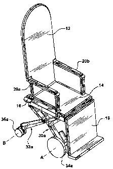
[0009] Figures 1 and 2 show an apparatus 10 for transporting an invalid
according to an embodiment of the present invention. The apparatus includes
a pivotable backrest 12 which is connected to a rear edge of a seat portion 14
by a hinge 16. A leg support 18 is pivotably connected to a front edge of the
seat portion 14, as described in more detail below. Foldable arm rests 20a,
20b which connect to the backrest 12 and seat portion 14 may also be
provided.
[0010] Referring to Figures 1 and 3 (which shows the apparatus 10 in a
horizontal or stretcher position), the seat portion 14 includes a frame 17.
Preferably, a pair of middle legs 30a,b and a pair of rear legs 32a,b depend
downwardly from the frame. Middle wheels 34a,b are connected to lower
ends of middle legs 30a,b, respectively. Rear wheels 36a,b are connected to
lower ends of rear legs 32a,b, respectively. The middle wheels 34a,b define
CA 02566551 2006-10-31
-4-
a rotation axis A, and the rear wheels 36a,b define a rotation axis B.
Rotation
axes A and B are shown in Fig. 1. Preferably, the rear wheels, 36a,b are
conventional swiveling wheels.
[0011] Referring now to Figure 3, a pair of front legs 38a,b are also
preferably provided on the leg support 18. Front wheeis 40a,b are connected
to lower ends of front legs 38a,b. Preferably, front wheels 40a,b are able to
roll only in a forward direction (i.e. the front wheels are prevented from
rolling
backward) by any suitable means, such as anti-reverse bearings (not shown).
It will be understood by those skilled in the art that the apparatus 10 may be
constructed without front legs 38a,b. In an alternative embodiment, the front
wheels 40a,b may be mounted directly to the underside of leg support 18.
[0012] Continuing to refer to Fig. 3, leg worm drives 42a-f are provided
to extend (i.e. lower) and retract (i.e. raise) middle legs 30a,b, rear legs
32a,b,
and front legs 38a,b, respectively. The leg worm drives 42a-d which move
the middle legs 30a,b and rear legs 32a,b are mounted to the sides of the
frame 17. The leg worm drives 42d,f which drive the front legs are mounted
to the underside of the leg support 18.
[0013] Figure 4 shows leg worm drive 42c and rear leg 32a in detail.
Leg worm drive 42c includes a worm housing 50 which receives a threaded
worm rod 52. A conventional electric motor 54 which drives the worm rod 52
is mounted at one end of the worm housing 50. An internally threaded worm
follower 56 engages the worm rod 52. The rotation of the worm rod 52 by
electric motor 54 causes the worm follower 56 to move outwardly or inwardly
along the worm rod 52 (depending on the direction of the rotation of the worm
rod). Preferably, all of the leg worm drives 42a-f are substantially identical
to
leg worm drive 42c. Consequently, the remaining leg worm drives are not
illustrated in detail.
[0014] Continuing to refer to Figure 4, rear leg 32a is suspended from
worm drive 42c. Rear leg 32a includes a primary member 60 which is hinged
to the worm follower 56 at its upper end in any suitable fashion, such as by
pin hinge 62. At its bottom end, the primary member 60 is connected to rear
CA 02566551 2006-10-31
-5-
wheel 36a (shown in Fig. 3) also by pin hinge 62. A secondary member 64 is
hinged by pin hinge 62 to a proximate end 63 of the worm housing 50 at one
end and to a point along the length of primary member 60 at the other end. A
support member 66 is hinged to a lower end of the secondary member 64 and
extends generally parallel with primary member 60. The lower end of support
member 66 is connected to rear wheel 36a (shown in Figure 3). The
movement of the worm follower 56 toward the proximate end 63 of the worm
drive 42c causes the hinged assembly of primary member 60 and secondary
member 64 to extend downwardly away from the worm drive. The movement
of the worm follower 56 toward the distal end 68 causes the hinged assembly
of primary member 60 and secondary member 64 to retract upwardly toward
the worm drive. The extension and retraction of the primary member 60 of the
rear leg 32a in turn raises and lowers the rear wheel 36a. The support
member 66 acts to maintain the orientation of the rear wheel 36a in relation
to
the ground or floor surface.
[0015] Preferably, the rear leg 32b is identical to rear leg 32a and will
not be further described. The remaining legs (middle legs 30a,b and front
legs 38a,b) are preferably similar to rear leg 32a, with the difference being
that the remaining legs are constructed without support member 66. It will be
understood by those skilled in the art that the legs 30a,b, 32a,b, and 38a,b
may be constructed in any other suitable fashion which permits such legs to
be extended and retracted. For example, the legs may be constructed from
telescoping members.
[0016] Referring again to Figure 3, electric motors 70a,b are mounted
on the middle legs 30a,b, respectively, in order to drive middle wheels 34a,b.
The electric motors driving the middle wheels 34a,b permit the apparatus 10
to be self-propelled. In other words, the invalid can operate the apparatus
without assistance from an attendant.
[0017] Referring again to Figure 2, a backrest tilting arm 80 is
connected to a rear surface of the backrest 12. The other end of the backrest
tilting arm 80 is connected to a backrest worm drive 42g. The backrest worm
CA 02566551 2006-10-31
-6-
drive 42g is substantially identical to the leg worm drive 42c and will not be
further described. The backrest tilting arm 80 preferably comprises a first
member 82 (secured to backrest 12) hinged to a second member 84 by pin
hinge 62. The other end of the second member 84 is connected to the worm
follower 56 (shown in Fig. 4) of backrest worm drive 42g also by pin hinge 62.
Accordingly, backrest worm drive 42g moves the backrest tilting arm 80,
which in turn tilts the backrest 12.
[0018] Referring again to Figure 3, a leg support tilting arm 90 is
provided to raise and lower the leg support 18. One end of leg support tilting
arm 90 is connected to the underside of leg support 18 by pin hinge 62. The
other end of leg support tilting arm 90 is connected to worm follower 56
(shown in Fig. 4) of a leg support worm drive 42h. The leg support worm drive
42h is substantially identical to the leg worm drive 42c and will not be
further
described. The leg support worm drive 42h moves the leg support tilting arm
90 to raise and lower the leg support 18.
[0019] Referring to Figure 5, the frame 17 preferably comprises two
telescoping slide raiis 100a, 100b running along opposing sides of the seat
portion 14 (not shown in Fig. 5 for clarity). A seat worm drive 42i is
provided
to slide the seat portion 14 on slide rails 100a, 100b. The worm housing 50 of
seat worm drive 42i is secured to slide rail 100b by bracket 102. The worm
follower 56 of seat worm drive 42i is secured to the underside the seat
portion
14 by connector 104.
[0020] Referring now to Figure 6, each slide rail 100a, 100b preferably
comprises three telescoping members to permit the seat portion 14 (shown in
Fig. 1) to translate by a distance of preferably at least 100% of its length.
In
particular, a middle 110 rail is received within a channel 111 of an outer
rail
112. An inner rail 114 slides within another channel 116 of the middle rail
110. Bearings 118 may be provided to facilitate the sliding movement. The
sliding rails 100a, 100b permit the seat worm drive 42i to slide the seat
portion 14 forward and backward in relation to the rotation axis A, B of the
middle wheels 34a,b and rear wheels 36a,b. The seat worm drive 42h is
CA 02566551 2006-10-31
-7-
substantially identical to the leg worm drive 42c and will not be further
described.
[0021] A battery (not shown) and any suitable control system (not
shown), such as a conventional electronic control system may be provided to
operate electric motors 70a, 70b and the worm drives 42a-i. The battery or
batteries may be mounted under the seat portion 14 or behind the backrest
12. The electronic control system may be linked to an actuator module (not
shown) operated by the invalid. The actuator module may be mounted on the
armrests 20. The actuator module may include one or more joysticks or levers
to control the various movements (described above) of the apparatus 10.
(0022] It will be understood by those skilled in the art that use of the
worm drives 42a-i is not essential. Any other suitable mechanism (such as
hydraulics, servo motors, or the like) may be used to move the legs 30, 32,
38, backrest 12, leg support 18, and seat portion 14.
[0023] The operation of the preferred embodiment of the present
invention will now be described with reference to Figures 7A-J and 8A-F. The
operation will be described in connection with the apparatus 10 entering and
exiting a vehicle. However, it will be understood by those skilled in the art
that
the apparatus 10 may exit or enter any other raised surface (either enclosed
or not) in the same manner.
[0024] The operation of the apparatus 10 in connection with entering
the vehicle will be described first with reference to Figures 7A-J.
[0025] The apparatus 10 is typically in the position shown in Figure 7A
for wheelchair operation. When the invalid wishes to transport herself onto a
vehicle or other raised surface, the invalid first drives the apparatus 10
forward in proximity of the raised surface 150.
[0026] Referring to Figure 7B, the invalid raises the leg support 18 into
a substantially horizontal position and drives the apparatus forward until the
middle wheels 34a, 34b are adjacent to the edge 152 of the raised surface
150.
CA 02566551 2006-10-31
-$-
[0027] Referring to Figure 7C, front legs 38a, 38b then extend to lower
front wheels 40a,b onto the raised surface 150. If required due to height
restrictions (such as a vehicle roof), the backrest 12 may be lowered (not
shown in lowered position) to a height sufficient to clear vehicle roof or to
a
horizontal stretcher position at this stage.
[0028] Referring now to Figure 7D, the slide rails 100a,b extend to slide
seat portion 14 forward relative to the rotational axis A (shown only in Fig.
1)
of middle wheels 34a,b until the center of gravity of the invaiid is
preferably
located forward of the rotational axis A. The force of the mass of the invalid
acting through the center of gravity is indicated on Figure 7D by arrow CG.
[0029] Referring to Figure 7E, the middle wheeis 34a,b are then raised
to a height above the raised surface 150.
[0030] Referring to Figure 7F, the slide rails 100a,b (not shown in Fig.
7F) retract causing the middle wheels 34a,b and rear wheels 36a,b to roll
forward, such that middle wheels 34a,b are above the raised surface 150. At
the same time, the seat portion slides backward relative to rotational axis A
(shown only in Fig. 1). All of this occurs due to the fact that the front
wheels
40a,b are prevented from rolling backwards by the anti-reverse bearings.
[0031] Referring to Figure 7G, middle legs 30a,b then lower the middle
wheels 34a,b such that they are in contact with the raised surface 150.
[0032] Referring to Figure 7H, the seat portion 14 again slides forward
relative to the rotational axis A of middle wheels 34a,b such that the center
of
gravity CG of the invalid is forward of the rotational axis A.
[0033] Referring to Figure 71, the rear legs 32a,b retract rear wheels
36a,b to a height above the raised surface. The apparatus 10 drives forward
to a position where the rear wheels 36a,b are above the raised surface.
[0034] Referring to Figure 7J, the rear wheels 36a,b are then lowered
until they are in contact with the raised surface. The slide rails 100a,b are
retracted such that the middle wheels 34a,b and rear wheels 36a,b again roll
forward on the raised surface. The seat portion 14 moves backward relative
CA 02566551 2006-10-31
-9-
to rotation axis A to position the center of gravity CG of the invalid between
the middle and rear wheels. In addition, depending on the height of the
vehicle roof, the backrest 12 may be adjusted for comfort of the invalid.
[0035] The operation of the apparatus 10 in connection with exiting the
vehicle will now be described with reference to Figures 8A-F.
[0036] Referring to Figure 8A, the apparatus 10 is driven forward until
the front wheels 40a,b overhang the edge 152 of the raised surface 150. The
front wheels 40a,b are then lowered until they are in contact with the ground
surface 160.
[0037] Referring to Figure 8B, the seat portion 14 then slides forward
on slide rails 100a,b until the center of gravity CG of the invalid is forward
of
rotation axis A of middle wheels 34a,b. This causes the front wheels 40a,b to
move forward, further away from the edge 152 of the raised surface 150.
[0038] Referring to Figure 8C, the slide rails 100a,b retract causing the
middle wheels 34a,b and rear wheels 36a,b to roll forward due to the anti-
reverse bearing on the front wheels 40a,b. As a result, the middle wheels
34a,b overhang the edge 152 of the raised surface 150. The center of gravity
CG of the invalid is positioned between the rotation axes A and B (shown only
in Fig. 1) of the middle and rear wheels, respectively.
[0039] Referring to Figure 8D, the middle wheels 34a,b are then
lowered until they are in contact with the ground surface 160. The slide rails
100a,b again extend to slide the seat portion 14 forward such that the center
of gravity CG of the invalid is forward of rotation axis A.
[0040] Referring to Figure 8E, the apparatus 10 then drives forward
until the rear wheels 36a,b clear the edge 152 of the raised surface 150. The
rear wheels are lowered until they are in contact with the ground surface 160.
[0041] Referring to Figure 8F, the slide rails 100a,b again retract
causing the middle wheels 34a,b and rear wheels 36a,b to roll forward on the
ground surface and causing the seat portion 14 to slide backward in relation
to rotational axis A.
CA 02566551 2008-08-26
-10-
[0042] The front wheels 40a,b are then retracted and the leg support
18 is lowered to place the apparatus 10 in a wheelchair position shown in
Figure 1.
[0043] The present invention provides the advantage of permitting the
invalid to transport herself in the apparatus 10 to and from raised surfaces
of
varying heights without the need of an attendant (either to push a wheelchair
or to bear any weight of the invalid while moving the chair to or from a
raised
surface).
[0044] While the present invention as herein shown and described in
detail is fully capable of attaining the above-described objects of the
invention,
it is to be understood that it is the presently preferred embodiment of the
present invention and thus, is representative of the subject matter which is
broadly contemplated by the present invention, that the scope of the present
invention fully encompasses other embodiments which may become obvious
to those skilled in the art, and that the scope of the present invention is
accordingly to be limited by nothing other than the appended claims, in which
reference to an element in the singular is not intended to mean "one and only
one" unless explicitly so stated, but rather "one or more." All structural and
functional equivalents to the elements of the above-described preferred
embodiment that are known or later come to be known to those of ordinary
skill in the art are intended to be encompassed by the present claims.
Moreover, it is not necessary for a device or method to address each and
every problem sought to be solved by the present invention, for it to be
encompassed by the present claims.