Language selection

Search

Patent 2566802 Summary

Third-party information liability

Some of the information on this Web page has been provided by external sources. The Government of Canada is not responsible for the accuracy, reliability or currency of the information supplied by external sources. Users wishing to rely upon this information should consult directly with the source of the information. Content provided by external sources is not subject to official languages, privacy and accessibility requirements.

Claims and Abstract availability

Any discrepancies in the text and image of the Claims and Abstract are due to differing posting times. Text of the Claims and Abstract are posted:

  • At the time the application is open to public inspection;
  • At the time of issue of the patent (grant).
(12) Patent: (11) CA 2566802
(54) English Title: METHODS AND APPARATUS FOR INJECTING FLUIDS INTO TURBINE ENGINES
(54) French Title: METHODES ET DISPOSITIF D'INJECTION DE FLUIDES DANS DES TURBOMACHINES
Status: Expired and beyond the Period of Reversal
Bibliographic Data
(51) International Patent Classification (IPC):
  • F23R 03/28 (2006.01)
  • F02C 07/22 (2006.01)
  • F23D 11/38 (2006.01)
(72) Inventors :
  • MARAKOVITS, STEVE (United States of America)
  • DURBIN, MARK (United States of America)
(73) Owners :
  • GENERAL ELECTRIC COMPANY
(71) Applicants :
  • GENERAL ELECTRIC COMPANY (United States of America)
(74) Agent: CRAIG WILSON AND COMPANY
(74) Associate agent:
(45) Issued: 2014-04-15
(22) Filed Date: 2006-11-02
(41) Open to Public Inspection: 2007-05-07
Examination requested: 2011-10-27
Availability of licence: N/A
Dedicated to the Public: N/A
(25) Language of filing: English

Patent Cooperation Treaty (PCT): No

(30) Application Priority Data:
Application No. Country/Territory Date
11/268,043 (United States of America) 2005-11-07

Abstracts

English Abstract

A method facilitates operating a gas turbine engine (10). The method comprises supplying steam and primary fuel to a chamber (160) within a nozzle (50), mixing the primary fuel and steam within the chamber, and discharging the mixture into a combustor (16) from a plurality of circumferentially spaced mixture outlets (104).


French Abstract

Méthode facilitant l'exploitation d'une turbine à gaz (10) et consistant à fournir de la vapeur et un combustible primaire à une enceinte (160) dans une buse (50), à mélanger le combustible primaire avec la vapeur dans l'enceinte et à libérer le mélange dans une chambre de combustion (16) à partir d'une multitude de sorties de mélange espacées de manière circonférentielle (104).

Claims

Note: Claims are shown in the official language in which they were submitted.

WHAT IS CLAIMED IS:
1. A method of operating a gas turbine engine wherein the nozzle
includes a first chamber and a second chamber defined separately therein, said
method
comprising:
supplying pilot fuel to the first chamber during preselected engine
operations;
supplying primary fuel and steam to the second chamber during other
preselected engine operations to facilitate mixing of the primary fuel and the
steam;
mixing the primary fuel and the steam within a tip of the nozzle; and
discharging the mixture of primary fuel and steam from the nozzle tip
through a plurality of mixture outlets defined in the nozzle tip.
2. A method in accordance with claim 1 wherein the nozzle tip is
substantially circular and includes a centerline extending through the nozzle,
wherein
said discharging the mixture of primary fuel and steam from the nozzle further
comprises discharging the mixture from the nozzle through a plurality of
mixture
outlets defined at a first radial distance outward from the centerline.
3. A method in accordance with claim 2 further comprising
discharging pilot fuel through a plurality of pilot fuel outlets defined at a
second radial
distance outward from the centerline.
4. A method in accordance with claim 1 further comprising
discharging pilot fuel through a plurality of pilot fuel outlets defined in
the nozzle tip
and radially inward from the plurality of mixture outlets.
5. A method in accordance with claim 1 further comprising
discharging the mixture of primary fuel and steam at a discharge angle that is
substantially parallel to a centerline extending through the nozzle tip.
6. A method in accordance with claim 1 further comprising
discharging the pilot fuel at an oblique angle from the nozzle tip with
respect to a
centerline extending through the nozzle tip.
-6-

7. A nozzle tip for a turbine engine fuel nozzle, said nozzle tip is
substantially circular and includes a centerline extending therethrough, said
tip
comprising:
an annular body comprising:
a first chamber in flow communication with a pilot fuel source for
discharging pilot fuel only during preselected engine operations; and
a second chamber in flow communication with a primary fuel source
and a steam source for discharging a mixture of primary fuel and steam during
other
preselected engine operations wherein said primary fuel and steam mixture is
configured to be discharged from said second chamber through a plurality of
mixture
outlets defined at a first radial distance outward from said centerline.
8. A nozzle tip in accordance with claim 7 wherein said first and
second chamber are separate such that pilot fuel in said first chamber does
not mix
with primary fuel and steam in said second chamber.
9. A nozzle tip in accordance with claim 7 wherein pilot fuel is
configured to be discharged from said first chamber through a plurality of
pilot fuel
outlets defined at a second radial distance outward from said centerline.
10. A nozzle tip in accordance with claim 9 wherein said first radial
distance is longer then said second radial distance.
11. A nozzle tip in accordance with claim 7 wherein said plurality of
mixture outlets are configured to discharge primary fuel and steam mixture
from said
nozzle tip at an oblique angle with respect to said centerline.
12. A nozzle tip in accordance with claim 7 wherein said nozzle tip is
configured to discharge pilot fuel at an oblique angle with respect to said
centerline.
13. A gas turbine engine comprising:
a combustor; and
a nozzle tip in flow communication with said combustor, said fuel nozzle
tip is substantially circular and includes a centerline extending
therethrough, said fuel
nozzle tip further comprising:
-7-

an annular body comprising:
a first chamber in flow communication with a pilot fuel source
for discharging pilot fuel into said combustor only during preselected engine
operations; and
a second chamber in flow communication with a primary fuel
source and a steam source for discharging a mixture of primary fuel and steam
into
said combustor during other preselected engine operations, the primary fuel
and steam
mixture is configured to be discharged from said second chamber through a
plurality
of mixture outlets defined at a first radial distance outward from said
centerline.
14. A gas turbine engine in accordance with claim 13 wherein said first
and second chamber are separate such that pilot fuel in said first chamber
does not
mix with primary fuel and steam in said second chamber.
15. A gas turbine engine in accordance with claim 13 wherein pilot fuel
is configured to be discharged from said first chamber through a plurality of
pilot fuel
outlets defined at a second radial distance outward from said centerline.
16. A gas turbine engine in accordance with claim 15 wherein said first
radial distance is longer then said second radial distance.
17. A gas turbine engine in accordance with claim 7 wherein said nozzle
tip is configured to discharge pilot fuel and fuel/steam mixture at an oblique
angle
with respect to said centerline.
-8-

Description

Note: Descriptions are shown in the official language in which they were submitted.


CA 02566802 2006-11-02
183255 (13DV)
METHODS AND APPARATUS FOR INJECTING FLUIDS INTO
TURBINE ENGINES
BACKGROUND OF THE INVENTION
Th Ls application relates generally to gas turbine engines and, more
particularly, to
methods and apparatus for injecting fluids into turbine engines.
Air pollution concerns worldwide have led to stricter emissions standards both
domestically and internationally. These same standards have caused turbine
engine
manufacturers to design more efficient engines, as well as design improved
retrofit
components that enable engines to operate more efficiently, with improved
emissions,
and/or with extended useful life and reliability. Moreover, the generally high
capital
costs associated with the purchase and maintenance of turbine engines, such as
revenue losses generated during engine outages, have caused the same engine
manufacturers to attempt to design engines that are more reliable and that
have
extended useful life.
Controlling the mixture of fluids, i.e. gas and steam, delivered to a gas
turbine engine
may be critical to the engine's performance. Typically, gas turbine engines
operating
with gas and steam do not meet emissions requirements at all operating
conditions,
and in particular, such engines generally do not satisfy carbon monoxide (CO)
emission requirements as well as other known engines. For example, at least
some
known gas turbine engines utilizing gas and steam generate higher CO emissions
than
gas turbine engines utilizing gas and water. More specifically poor mixing of
the gas
and steam may cause fuel to remain inboard, leading to higher CO emissions
being
generated. Moreover, poor mixing may cause the recirculation stability zone
within
the combustor to be shifted downstream, which may cause the flame to become
detached, resulting in the generation of CO emissions.
-1-

CA 02566802 2006-11-02
183255 (13DV)
BRIEF DESCRIPTION OF THE INVENTION
In one aspect, a method of operating a gas turbine engine is provided. The
method
comprises supplying primary fuel to a chamber within a nozzle, supplying steam
to
the chamber, and mixing the primary fuel and steam in the chamber prior to
discharging the mixture into the combustor from at least one outlet spaced
circumferentially around, and extending outward from, a centerline extending
through
the nozzle.
In another aspect, a nozzle tip for a turbine engine fuel nozzle is provided.
The tip
includes an annular body including two chambers, at least one pilot fuel
outlet, and at
least one fuel mixture outlet. The at least one pilot fuel outlet is
configured to
discharge pilot fuel from one of the two chambers within the fuel nozzle tip.
The at
least one fuel mixture outlet is configured to discharge a mixture of primary
fuel and
steam from the second chamber of the fuel nozzle tip. The second chamber is
configured to pre-mix the primary fuel and steam prior to discharging the
mixture
from the fuel nozzle tip.
In a further aspect, a gas turbine engine is provided. The gas turbine engine
includes
a combustor and a fuel nozzle including a fuel nozzle tip. The fuel nozzle tip
includes
an annular body including two chambers, at least one pilot fuel outlet. and at
least one
fuel mixture outlet. The at least one pilot fuel outlet is configured to
discharge pilot
fuel to the combustor only during pre-selected engine operations. The at least
one
fuel outlet is configured to release a mixture of primary fuel and steam into
the
combustor when more power is demanded by the gas turbine engine.
BRIEF DESCRIPTION OF THE DRAWINGS
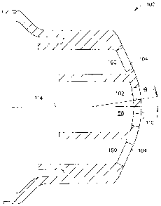
Figure 1 is a schematic illustration of an exemplary gas turbine engine;
Figure 2 is a cross-sectional view of an exemplary embodiment of a fuel nozzle
that
may be used with the gas turbine engine shown in Figure 1;
Figure 3 is a perspective of an exemplary fuel nozzle tip that may be used
with the
fuel nozzle shown in Figure 2; and
-2-

CA 02566802 2006-11-02
183255 (I3DV)
Figure 4 is a cross-sectional view of the fuel nozzle tip shown in Figure 3.
DETAILED DESCRIPTION OF THE INVENTION
Figure 1 is a schematic illustration of an exemplary gas turbine engine 10
including a
low pressure compressor 12, a high pressure compressor 14, and a combustor 16.
Engine 10 also includes a high pressure turbine 18 and a low pressure turbine
20.
Compressor 12 and turbine 20 are coupled by a first shaft 22, and compressor
14 and
turbine 18 are coupled by a second shaft 21. In one embodiment, gas turbine
engine
is an LM2500 engine commercially available from General Electric Aircraft
Engines, Cincinnati, Ohio.
In operation, air flows through low pressure compressor 12 supplying
compressed air
from low pressure compressor 12 to high pressure compressor 14. The highly
compressed air is delivered to combustor 16. Airflow from combustor 16 is
channeled through a turbine nozzle to drive turbines 18 and 20, prior to
exiting gas
turbine engine 10 through an exhaust nozzle 24. As is known in the art, gas
turbine
engines further include fuel nozzles (not shown) which supply fuel to the
combustor 16.
Figure 2 is a side schematic cross-sectional view of an exemplary embodiment
of a
fuel nozzle 50 that may be used with a gas turbine engine such as gas turbine
engine
10 (shown in Figure 1). Fuel nozzle 50 includes a pilot fuel circuit 52, a
primary fuel
circuit 54, and a steam circuit 56. Pilot fuel circuit 52 delivers pilot fuel
through the
center of nozzle 50 to the end 58 of nozzle 50 during start-up and idle
operations.
End 58 is configured to discharge pilot fuel into the combustor 16 (shown in
Figure 1)
of gas turbine engine 10. Primary fuel circuit 54 and steam circuit 56 are
positioned
radially outward from, and circumferentially around, pilot fuel circuit 52.
Primary
fuel circuit 54 and steam circuit 56 deliver primary fuel and steam,
respectively, to
combustor 16 through nozzle end 58. More specifically, primary fuel and steam
are
each discharged through nozzle end 58 into a combustion zone defined
downstream
from nozzle 50 within combustor 16.
Figure 3 is a perspective view of an exemplary fuel nozzle tip 100 that may be
used
with a gas turbine engine, such as turbine engine 10 (shown in Figure 1).
Figure 4 is a
-3-

CA 02566802 2006-11-02
183255 (13DV)
cross-sectional view of nozzle tip 100. Nozzle tip 100 includes a plurality of
pilot
fuel outlets 102 and a plurality of fuel mixture outlets 104. Pilot fuel
outlets 102 are
spaced circumferentially about, and radially outward from, a center 110 of
fuel nozzle
tip 100.
In the exemplary embodiment, pilot fuel outlets 102 are oriented obliquely
with
respect to centerline 114 extending through nozzle tip 100. As such, pilot
fuel
discharged from outlets 102 is expelled outward from tip 100 at an oblique
angle 0
away from centerline 114 and toward fuel mixture being discharged from fuel
mixture
outlets 104. In the exemplary embodiment, nozzle tip 100 includes four pilot
fuel
outlets 102. In alternative embodiments, nozzle tip 100 includes more or less
then
four pilot fuel outlets 102. As will be appreciated by one of ordinary skill
in the art,
the number of pilot fuel outlets 102 varies depending on the application of
fuel nozzle
tip 100.
Fuel mixture outlets 104 are spaced circumferentially around, and radially
outward
from, pilot fuel outlets 102. Furthermore, fuel mixture outlets 104 are
configured to
discharge a fuel/steam mixture from a chamber 160 (shown in Figure 2) defined
within fuel nozzle tip 100. In the exemplary embodiment, fuel mixture outlets
104 are
oriented substantially parallel to centerline 114. In an alternative
embodiment, fuel
mixture outlets are oriented obliquely with respect to centerline 114. As
such, fuel
mixture discharged from fuel mixture outlets 104 is expelled outward from tip
100
substantially parallel to centerline 114.
During operation pilot outlets 102 discharge pilot fuel into the combustor
during start
up or idle operations of the gas turbine engine. When additional power is
demanded,
primary fuel and steam are mixed within chamber 160 and discharged through
fuel
mixture outlet 104 into a combustion zone defined in the combustor of a gas
turbine
engine. Because primary fuel and steam are mixed prior to being discharged
into the
combustion zone, the lean mixture provides lower emissions than a non-premixed
nozzle tip. Accordingly, the enhanced mixing of primary fuel and steam within
nozzle tip 100 facilitates maintaining a more stable flame within the
combustion zone
-4-

CA 02566802 2013-04-25
. 183255 (13DV)
defined in the combustor. Generally, controlling the stability of the flame
facilitates
reducing generation of CO emissions within the combustor.
As used herein, an element or step recited in the singular and proceeded with
the word
"a" or "an" should be understood as not excluding plural said elements or
steps,
unless such exclusion is explicitly recited. Furthermore, references to "one
embodiment" of the present invention are not intended to be interpreted as
excluding
the existence of additional embodiments that also incorporate the recited
features.
The above described fuel nozzle tip for a gas turbine engine provides an
engine
capable of meeting emissions standards. The fuel nozzle tip includes a chamber
wherein the primary fuel and steam can be premixed before being discharged
into the
combustor. As a result, a more stable flame is maintained with the combustion
zone
defined with the combustor, which facilitates reducing the generation of CO
emissions.
Although the methods and systems described herein are described in the context
of
supplying fuel to a gas turbine engine, it is understood that the fuel nozzle
tip methods
and systems described herein are not limited to gas turbine engines. Likewise,
the
fuel nozzle tip components illustrated are not limited to the specific
embodiments
described herein, but rather, components of the fuel nozzle tip can be
utilized
independently and separately from other components described herein.
While there have been described herein what are considered to be preferred and
exemplary embodiments of the present invention, other modifications of these
embodiments falling within the invention described herein shall be apparent to
those
skilled in the art.
-5-

Representative Drawing
A single figure which represents the drawing illustrating the invention.
Administrative Status

2024-08-01:As part of the Next Generation Patents (NGP) transition, the Canadian Patents Database (CPD) now contains a more detailed Event History, which replicates the Event Log of our new back-office solution.

Please note that "Inactive:" events refers to events no longer in use in our new back-office solution.

For a clearer understanding of the status of the application/patent presented on this page, the site Disclaimer , as well as the definitions for Patent , Event History , Maintenance Fee  and Payment History  should be consulted.

Event History

Description Date
Time Limit for Reversal Expired 2018-11-02
Letter Sent 2017-11-02
Grant by Issuance 2014-04-15
Inactive: Cover page published 2014-04-14
Inactive: Final fee received 2014-01-30
Pre-grant 2014-01-30
Notice of Allowance is Issued 2013-08-06
Letter Sent 2013-08-06
Notice of Allowance is Issued 2013-08-06
Inactive: Approved for allowance (AFA) 2013-07-29
Amendment Received - Voluntary Amendment 2013-04-25
Inactive: S.30(2) Rules - Examiner requisition 2012-11-15
Letter Sent 2011-11-03
Request for Examination Requirements Determined Compliant 2011-10-27
All Requirements for Examination Determined Compliant 2011-10-27
Request for Examination Received 2011-10-27
Application Published (Open to Public Inspection) 2007-05-07
Inactive: Cover page published 2007-05-06
Inactive: IPC assigned 2007-05-03
Inactive: First IPC assigned 2007-05-03
Inactive: IPC assigned 2007-05-03
Inactive: Filing certificate - No RFE (English) 2006-12-06
Letter Sent 2006-12-06
Application Received - Regular National 2006-12-06

Abandonment History

There is no abandonment history.

Maintenance Fee

The last payment was received on 2013-10-18

Note : If the full payment has not been received on or before the date indicated, a further fee may be required which may be one of the following

  • the reinstatement fee;
  • the late payment fee; or
  • additional fee to reverse deemed expiry.

Patent fees are adjusted on the 1st of January every year. The amounts above are the current amounts if received by December 31 of the current year.
Please refer to the CIPO Patent Fees web page to see all current fee amounts.

Owners on Record

Note: Records showing the ownership history in alphabetical order.

Current Owners on Record
GENERAL ELECTRIC COMPANY
Past Owners on Record
MARK DURBIN
STEVE MARAKOVITS
Past Owners that do not appear in the "Owners on Record" listing will appear in other documentation within the application.
Documents

To view selected files, please enter reCAPTCHA code :


To view images, click a link in the Document Description column. To download the documents, select one or more checkboxes in the first column and then click the "Download Selected in PDF format (Zip Archive)" or the "Download Selected as Single PDF" button.

List of published and non-published patent-specific documents on the CPD .

If you have any difficulty accessing content, you can call the Client Service Centre at 1-866-997-1936 or send them an e-mail at CIPO Client Service Centre.


Document
Description 
Date
(yyyy-mm-dd) 
Number of pages   Size of Image (KB) 
Abstract 2006-11-01 1 12
Claims 2006-11-01 2 71
Drawings 2006-11-01 4 56
Description 2006-11-01 5 226
Representative drawing 2007-04-19 1 5
Description 2013-04-24 5 228
Claims 2013-04-24 3 120
Courtesy - Certificate of registration (related document(s)) 2006-12-05 1 106
Filing Certificate (English) 2006-12-05 1 158
Reminder of maintenance fee due 2008-07-02 1 113
Reminder - Request for Examination 2011-07-04 1 119
Acknowledgement of Request for Examination 2011-11-02 1 176
Commissioner's Notice - Application Found Allowable 2013-08-05 1 163
Maintenance Fee Notice 2017-12-13 1 180
Correspondence 2014-01-29 1 35