Note: Descriptions are shown in the official language in which they were submitted.
CA 02566882 2006-11-15
WO 2005/113111 PCT/GB2005/002013
1
FLUID FILTER
The present invention relates to a fluid filter, and particularly although not
exclusively to a high pressure and throughput filter for removing solid
material
from a liquid such as water.
A filter which makes use of fibres to trap material entrained within the
medium
is disclosed in US patents US-A-5470470 and US-A-4617120. A similar
device is disclosed in EP-A-0280052.
The principle of operation of the device of EP-A-0280052 is shown
schematically in figures 1 and 1 a. The filter 100 comprises a filter housing
101
with an inlet end 102 and an outlet end 103. Extending longitudinally of the
housing are a plurality of parallel fibres, held in place by a support 106.
Surrounding the fibres is a flexible waterproof membrane 104.
During filtration, the membrane 104 is pressurised as shown at 107 in figure
1 a, thereby compressing the fibres towards an internal pinch point 108. The
material to be filtered is forced through the filter in the direction shown by
the
arrow. The filter may be flushed and cleaned by releasing the pressure within
the membrane and back-flushing in the opposite direction to the normal flow of
filtration.
In one particular embodiment, EP-A-0280052 discloses a distensible balloon
with fibres surrounding it, so that as the balloon is distended the fibres get
pushed out against the internal circumference of the filter housing.
In the embodiments described, the liquid to be filtered passes up through the
loosely hanging fibres against the flow of gravity. This exemplifies the
CA 02566882 2006-12-04
2
conventional understanding of filters of this type, namely that regular flow
between each of the individual fibres can be expected only when the liquid
goes in the direction indicated since only in that way are the fibres free to
move
one with respect to another to equalise the amount of fluid passing along the
individual passageways between the fibres. The disadvantage is that flow rates
and pressures are limited since if too high a pressure is applied at the free
end
the fibres will start to buckle up and get entangled with each other.
The present invention arises from the unexpected realisation that this prior
understanding is in fact wrong. There is no need whatsoever for the fluid to
pass in the direction shown, and the applicant has realised that if the flow
direction is reversed the fluid still finds its way fairly evenly along the
multitude of passages between the fibres. This fact does not depend as might
be expected on being very careful in the way in which the fibres are mounted
at
one end, nor on the provision of a large number of small individual apertures
within a mounting plate to allow the fluid to enter each and every one of the
passages. On the contrary, the applicant has found that the way in which the
fluid is supplied to the fibres at their fixed end is not at all critical,
making it
possible for the first time to provide very high volume and/or pressure
filters at
low cost.
According to the present invention there is provided a filter comprising a
filter
housing having an inlet end and an outlet end, a distensible member extending
longitudinally of the housing, and a plurality of fibres extending
longitudinally
of the housing and being secured at the inlet end, whereby when the
distensible
member is distended the fibres are compressed against the housing to create a
graduated filter matrix between the inlet end and a pinch area between the
distensible member and an inner surface of the housing. This creates a
272816v1
CA 02566882 2006-12-04
3
graduated or step-less filter. Recesses or ridges are provided on the surface
of
the distensible member or on the inner surface of the housing.
According to a further aspect of the present invention there is provided a
method of operating a filter having a filter housing with a first end and a
second end, a distensible member extending longitudinally of the housing. A
plurality of fibres extend longitudinally of the housing and are secured at
the
first end. The method comprises distending the distensible member to
compress the fibres against the housing to create a graduated filter matrix
between the first end and a pinch area between the distensible member and an
inner surface of the housing; and passing a fluid to be filtered from the
first end
to the second end.
The invention may be carried into practice in a number of ways, and several
specific embodiments will now be described by, way of example, with
reference to the accompanying drawings, in which:
Figure 1 is a longitudinal section through a prior art filter;
Figure 1 a is a longitudinal section through the filter of figure 1 in
filtration
mode;
Figure 2 is a longitudinal section through a first embodiment of the present
invention;
Figure 2a is a longitudinal section through a second embodiment of the present
invention;
Figure 2b is a longitudinal section through a third embodiment of the
invention;
Figure 2c is a longitudinal section through a fourth embodiment of the
invention;
272816v1
CA 02566882 2006-12-04
3a
Figure 3 is a detailed plan view of the head matrix of each of the
embodiments;
Figure 4 is a longitudinal section showing the filter of figure 2 in
filtration
mode; and
272816v1
CA 02566882 2006-11-15
WO 2005/113111 PCT/GB2005/002013
4
Figure 5 is a longitudinal section of the filter of figure 2 in flushing mode.
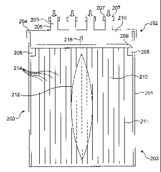
Turning first to figure 2, there is shown a filter 200 of a first embodiment
of the
invention. The filter is contained within a cylindrical filter housing 201 the
size of which may be selected according to the particular fluid pressures,
flow
rates or volumes required. Alternatively, the housing could be shaped so that
its
width tapers towards its distal ends. For example, in a specific application
the
housing has an external diameter of 315mm and an internal diameter of
290mm. The filter housing can be made of any suitable rigid material such as
metal or an appropriate plastics material. The housing has an inlet end 202
and
an outlet end 203, respectively allowing the filtered medium to ingress to.
and
to egress from the filter.
The inlet end is capped by means of an inlet cap 204 having a plurality of
inlet
apertures 205. Each of these is supplied by an individual inlet pipe 206,
thereby allowing if required for a variety of liquids and/or gases to be
supplied
in parallel to the filter. Suitable connecting means 207 are provided to
couple
the inlet pipes to further piping systems (not shown) which furnish the
liquids
and/or gases to the filter at the required pressure and flow rates.
Adjacent to the inlet end 202 of the housing 201 there is cast an internal
securing ring 208. This ring provides a lip upon which a head matrix 209 is
securely mounted. It is preferred, although not essential, that the head
matrix
209 be capable of being easily removed in order to facilitate maintenance
and/or replacement. The volume of the filter housing between the inlet cap 204
and the head matrix 209 defines an inlet chamber 210, within which the
incoming liquids and/or gases may mix.
CA 02566882 2006-11-15
WO 2005/113111 PCT/GB2005/002013
The outlet end 203 of the housing may be left open, as shown in figure 2, or
alternatively an exit cap and exit pipes (not shown) may be provided to direct
the outgoing fluid after it has passed through the filter.
5 Referring now to figure 3, the head matrix 209 consists of a removable plate
300, made from any suitable rigid materials (such as metal or a plastics
material) having a plurality of apertures spaced around the circumference for
the receipt of fibre bundles, one of which is shown at 303. The fibres may be
secured in any convenient way within the head matrix, for example by melting
together approximately 30mm of the fibre ends to form a solid mass and then
securing that mass by means of cross-struts (not shown) within the aperture
301. Between and surrounding the fibre bundle apertures 301 are a plurality of
smaller apertures 302, the purpose of which is to allow for the ingress of
fluid
through the head matrix. Both types of aperture are preferably spaced at
equidistant points around the circumference of the head matrix, so as to
provide
a generally uniform distribution of fibres and also a generally uniform fluid
flow between and through the fibre bundles.
Turning back now to figure 2, it will be seen that in a filtration chamber 213
below the head matrix the individual fibres 211 of the bundles 301 spread out
to form a fairly uniform fibre curtain around the periphery of the housing
201.
The fibres extend substantially axially along the length of the filtration
chamber 213, and are oriented substantially parallel to the direction of flow
through the chamber. In this embodiment, the ends of the fibres are not
secured in any way, and they simply hang loose.
The fibres 211 may be of any suitable dimension and material, depending upon
application. In one example, the fibres may be of polymer or nylon, with a
diameter of between 0.15mm and 0.5mm. The fibres maybe solid or hollow,
CA 02566882 2009-04-21
6
and may be of circular, rectangular or any other cross-section. For some
applications, it may be advantageous for the fibres to be at least partially
elastic, either along or across the fibre length. For such fibres, the desired
shape-recovery characteristic may also be chosen according to the required
application. The fibres may have a smooth or a rough surface and may if
required be coated. Fibre coatings such as TeflonTM and zinc may be
appropriate.
They may also if desired be electrically charged. Charging the fibres will
encourage ionisation, which may be important in some applications. Also it
may be desired for the fluid, the fibres, areas within the housing or any
combination of these to be magnetised.
In an alternative embodiment, shown in figure 2a, the fibres 211 may be
secured at the outlet end 203, rather than being left loose. In this
embodiment,
the lower fibre ends 215 are secured an outlet matrix head 216 having
apertures
(not shown) for securing the fibre bundles and further apertures (also not
shown) for egress of the filtrate. The outlet matrix head 216 is secured in
position in some suitable way, for example by means of a further ring 217 cast
on the inside of the filter housing 201. Alternatively, the outlet matrix head
216 could be left loose. In this arrangement the filter could be back flushed.
Turning back again to figure 2, it will be seen that secured within the centre
of
the filtration chamber 213 is an elongate balloon or distensible member 212.
The balloon is disposed centrally within the chamber and extends substantially
axially along the chamber so as to be oriented substantially parallel to the
direction of flow through the filter. In a first mode, shown in figure 2, the
balloon is relaxed and accordingly presents little or no obstruction to the
free
flow of fluid through the filter. Fluid entering through the apertures 302
passes
substantially unobstructed between the fibre bundles and between gaps 214
CA 02566882 2006-11-15
WO 2005/113111 PCT/GB2005/002013
7
between the individual fibres, before passing out of the outlet. No filtering
takes place in this mode, but a van der Walls effect may develop.
When it is desired to start filtering, the balloon 212 is inflated by means of
a
control fluid (hydraulic or pneumatic) which is supplied along an inlet
pipeline
216. Alternatively, the balloon could be filled with materials that are
substantially resistive to motion (be it rapid motion or slow motion) such as
a
powder or particles such as sand. As is shown in the drawing, the pipeline may
pass through the head matrix 209, or alternatively (not shown) the pipe may
avoid the head matrix by entering from the side or from the outlet end.
In the filtration mode of figure 4, the distended balloon defines a pinch
point
403 consisting of a narrow annular region or area between the perimeter of the
balloon and the inner circumference of the housing, where the available flow
area is at a minimum. The position of the pinch point 403 defines an upstream
section 406 on the inlet section of the pinch point, and a downstream section
407 on the outlet side. Preferably, the shape of the balloon is such that, in
its
distended state, it is substantially symmetrical about the central
longitudinal
axis 408 of the chamber. Depending upon the application, the upstream and
downstream sections may be mirror images of each other. Alternatively (not
shown) the upstream section may, define a more rapidly-changing annular area,
along the length of the filter, than the downstream section, or vice versa.
In any event, when the filter is in filtration mode, fluid passing through it
is
exposed to a gradually decreasing annular surface area up until the pinch
point
403, and then is exposed to a gradually increasing annular surface area. The
gradual nature of the decreasing surface area prior to the pinch point is
enhanced by making the balloon 212 stiffer at its ends and softer in the
middle
so that, as it inflates, it forms a generally ovoid shape.
CA 02566882 2006-11-15
WO 2005/113111 PCT/GB2005/002013
8
As the balloon expands, it starts to exert a radial force on the surrounding
fibres, forcing the fibres to press together and to press against the rigid
wall
201 of the filter housing. This of course reduces the size of the passageways
409 between the fibres.
If the fibres 211 are made of a compressible material, the fibres themselves
may start to deform, thereby reducing even further the size of the passageways
409 through which the fluid can pass.
Once the balloon has been expanded to the extent required, the fluid or fluids
to
be filtered are passed through the filter. Typically, the fluid may comprise
water or another liquid mixed with one or more solid particulates of varying
sizes. As the water and the particulates pass through the upstream section,
the
gradually decreasing passageway size causes the particulates to be trapped
between the fibres. Larger particulates 410 will be trapped relatively early,
whereas finer particulates 411 will be trapped at a point closer to the pinch
point 403. The very finest particles 412 will be trapped just prior to the
pinch
point.
The tapered and gradual increase in fibre compression within the upstream
section prevents the larger particles 410 which are caught in the coarser
filter
matrix, defined by the upper port of the upstream section, from slipping down.
This would of course be undesirable since larger particles which were to move
downwards towards the pinch point would tend to reduce the gradual nature of
the taper and hence the ability of the filter systematically to separate out
particles of differing sizes. In the embodiments of the present invention, the
gradual nature of the taper (combined in some embodiments with the natural
elasticity of the fibres) ensures that each fibre is securely held by the
fibres
CA 02566882 2006-11-15
WO 2005/113111 PCT/GB2005/002013
9
which surround it. The fibres in the upstream section cannot "flap around" or
move, with the consequence that the trapped particles cannot move either.
Typically, the balloon will be distended by an appropriate amount such that
only fluid can pass the pinch point. Of course, however, it will be understood
that in some applications it may be perfectly acceptable for very fine
particulates to pass the filter, in which case the balloon need not be
distended to
the same extent. By varying the hydraulic or pneumatic pressure on the line
216, the filter may be adjusted to allow through only particles which are
smaller than a desired size.
Where the fluids to be filtered include both a liquid and a gas, a bubble
generator (not shown) within the inlet chamber 210 may be used to ensure that
the fluid to be filtered is an intimate mixture of liquid and gaseous bubbles,
along with the particulates to be separated out. In some applications it may
be
convenient to introduce gaseous ozone to provide sterilisation during the
filtration process. Where a gas is introduced into the filter, bubbles of the
gas
may be cut to micro-bubbles (that is to say bubbles of particularly small
size,
down to the smallest possible bubble size). This provides a substantially
increased surface area of contact between the gas and the fluid to be
filtered,
greatly improving the aeration process. The entire unit may be turned to
facilitate the aeration process.
Figure 2b shows a slightly different embodiment in which the balloon 212 is of
a shape having flat upper 292 and lower 294 ends. The surface of the balloon
in the distended position is shown at 291, with the dotted line 290
representing
the surface of the balloon in the filtration mode. This figure also shows the
way in which the fibre bundles extend through the apertures 301 of the head
matrix 209. As the balloon expands and presses against these bundles, the
CA 02566882 2006-11-15
WO 2005/113111 PCT/GB2005/002013
fibres start to spread out fill the gaps between them, ultimately forming a
uniform filtration matrix within the annular space between the housing and the
periphery of the balloon.
5 In a further embodiment shown in Figure 2c, the filter includes two balloons
212a and 212b arranged in series along a central axis of the filter. The
fibres
211 surround the balloons such that when the balloons are inflated as shown in
Figure 2c, they compress the fibres together against the inner wall of the
housing. In this manner, more than one filter stage is provided, and the two
10 balloons 212a and 212b can be used to filter out two different types of
particles
based on particle size or on another characteristic.
As filtration continues, particles of varying sizes become trapped within the
upstream section 406, forming so-called "filter cake".
In the downstream area 407 beyond the pinch point 403, the fibres then
naturally spread out again. The gradual enlargement of the available annular
area for the filtrate, along with the presence of the fibres, encourages
smooth
and linear flow. The gradual enlargement of the area helps to create a Ventura
effect, which further helps the flow.
In some specific applications, the required filtration characteristics may be
achieved by providing ridges and/or recesses (not shown) on the surface of the
balloon and/or on the inner surface of the cylindrical wall 201.
Figure 5 schematically shows the flushing process. When the filter has been in
operation for some time, a quantity of filter cake will build up. This may be
removed by flushing.
CA 02566882 2006-11-15
WO 2005/113111 PCT/GB2005/002013
11
In order to flush the filter, the pressure within the balloon 212 is released,
thereby removing the compressive force from the fibres and allowing them to
return to their uncompacted and loose state as shown at 503. As the passages
504 increase in size, the fibres reduce their grip on the filter cake,
allowing the
cake to be washed through by means of a rinsing medium 505. This could be
any suitable cleaning liquid or gas, for example water, steam, or even the
medium to be filtered (with included particulates). The rinsing medium 505 is
passed through the filter in the same direction that the medium to be filtered
was passed through in the filtration mode: that is, the filter is forward-
flushed.
Appropriate valves 506 and piping 507 may be employed so that the washing
medium and the filter cake do not contaminate the filtrate. Upstream and/or
downstream pressure sensors 508, 509 may be used to determine when the
filter is overly clogged with filter cake, and when it is necessary to carry
out the
flushing process. The process may be carried out entirely automatically,
thereby maximising the time that the filter spends in the filtration mode, so
increasing throughput.
As part of the flushing process, ultrasound may be applied to the filter or to
the
fibres to help the cake shake loose. Also, it may be desired to dry the filter
cake before release by means such as generating a vacuum within the filter or
passing hot air through it.
It will of course be understood that although the flushing process described
above with reference to figure 5 will always be carried out in the forward
direction, in the alternative embodiment of figure 2a (in which the fibres are
anchored at both ends) a backward flush could be used instead or in addition,
in
each case either with or without releasing the balloon pressure.
CA 02566882 2006-11-15
WO 2005/113111 PCT/GB2005/002013
12
The filter of the present invention may be scaled in size as desired according
to
the volumes to be filtered and/or the application in hand. In one preferred
arrangement the filter may be manufactured as a plug-in module, in a variety
of
different sizes.
Although the filter is shown with its longitudinal axis vertical in the
drawings,
it will be understood that in some applications the axis may be horizontal.
The
fluid passing through the filter may be pumped, at high or low pressure, or
alternatively may be allowed to pass through the filter entirely by the
influence
of gravity.
It will be understood that the skilled man will be able to adjust a variety of
different parameters, as required according to the particular application in
hand.
Such adjustable parameters include pressure; temperature; fibre size; fibre
length; fibre coating; charge on fibre; magnetic field strength of areas
within
the housing, fibres or fluid; the manner in which the fibres are anchored;
flow
volume; filter housing material; type of feed; method of inflating the
balloon;
balloon taper; flushing materials volumes and pressures; and the addition of
gases to the mix.
There are a large number of specific applications which may benefit from the
use of a filter according to the present invention. Typical applications might
include:
1. Filtration for reverse osmosis.
2. The removal of cement, grit and so on following an industrial process
such as precast concrete.
3. Separation of coagulated products.
4. Separation of biological tissue.
CA 02566882 2006-11-15
WO 2005/113111 PCT/GB2005/002013
13
5. Separation of coagulated blood and the like.
6. Separation of vegetable matter, for example the waste water from olive
oil production.
7. Reducing the turbidity of water generally, where required for technical
or for legal reasons.
8. The removal of silt from a liquid/water.
9. Ballast water.