Note: Descriptions are shown in the official language in which they were submitted.
CA 02567538 2006-11-21
WO 2006/002515 PCT/CA2005/000845
CONTROL SYSTEM FOR A DYNAMIC FEED COINJECTION PROCESS
TECHNICAL FIELD
The present invention relates to control apparatus and method
for feeding a melt to a coinjection hot runner system.
Preferably, the present invention utilizes a Dynamic Clamp Feed
(DCF) to operate at least one of the coinjection shooting pots
for injecting at least two melt materials into a mold cavity.
Preferably, one of the melt materials is caused to reverse flow
into the nozzle melt channel of one of the other materials
during the process. Preferably, this decompression step occurs
after the refilling of the shooting pots.
BACKGROUND OF THE INVENTION
Coinjection molding is typically used to mold multi-layered
plastic packaging articles having a laminated wall structure.
Each layer is typically passed through a different annular or
circular passageway in a single nozzle structure and each layer
is partially, sequentially, injected through the same gate.
Some coinjection hot runner systems include shooting pots to
meter material of one plastic resin so that each cavity of a
multi-cavity mold receives an accurate dose of that resin in
the molding cycle. Such systems may also use shooting pots to
exert supplementary pressure on the melt during the molding
process. In such systems, a check valve is often used to
prevent backflow of resin into the shooting pot during the
injection of the resin into the mold cavity.
U.S. Patent Nos. 4,609,516 and 4,990,301, both to Krishnakumar,
disclose coinjection molding processes employing hot runner
systems that use shooting pots. Both of these patents disclose
sequence charts that show the sequence in which the multiple
materials are injected into the mold cavity.
U.S. Patent No. 6,152,721 to Schad discloses a shooting pot
actuator mechanism for operating the shooting pots of a
coinjection hot runner system.
1
CA 02567538 2006-11-21
WO 2006/002515 PCT/CA2005/000845
With current coinjection nozzle/shooting pot configurations,
however, resin material that is trapped between the check valve
and the valve gate during the different molding cycle steps
remains under pressure. This often results in unwanted
drooling or leakage of resin into the valve gate and/or the
mold cavity. In more detail, if a second resin in a
coinjection nozzle melt channel remains under pressure when the
valve gate stem is withdrawn to inject the next shot of the
first resin, a portion of the second resin moves to the front
of its melt channel and maybe into the gate area. Then, when
the next shot of the first resin moves through the gate, it
drags along that portion of the second resin. The presence of
the second resin in the shot of the first resin may result in a
defective part.. No known art discloses any means for relieving
this build up of pressure between the check valve and the valve
gate. Adapting new structures to act as a pressure relief
valve would add complicated mechanical structure to the molding
machine, leading to increased manufacturing and maintenance
costs.
Thus, what is needed is a coinjection molding control structure
which can relieve the pressure build up between the check valve
and the valve gate during the molding cycle. Preferably, such
a solution will require a minimum of new hardware and/or
software to implement and maintain.
SUMMARY OF THE INVENTION
It is an advantage of the present invention to overcome the
problems of the related art and to provide a coinjection
molding machine control system that will relieve the pressure
build up between the check valve and the valve gate during the
molding cycle. Preferably, the control system is adapted to
reduce the pressure on a second resin in a second melt channel
of a coinjection nozzle to allow a small amount of a first
resin to flow into the valve gate and perhaps into the second
melt channel in the coinjection nozzle, thus equalizing the
pressures and preventing the second resin from being dragged
into the cavity when the next shot of the first resin is
injected.
2
CA 02567538 2006-11-21
WO 2006/002515 PCT/CA2005/000845
According to a first aspect of the present invention, a novel
combination of structure and/or steps are provided for
coinjection molding system control apparatus including flow
control structure configured to cause a first melt to flow from
a first melt channel in a coinjection nozzle into a second melt
channel in the coinjection nozzle.
According to a second aspect of the present invention, a novel
combination of structure and/or steps are provided for a
coinjection mold including a mold cavity having a gate, and a
coinjection nozzle having a first melt channel and a second
melt channel. The coinjection nozzle is configured to (i)
inject a first melt into the mold cavity through the mold gate
and the first melt channel, and (ii) inject a second melt into
the mold cavity through the mold gate and the second melt
channel. A valve stem is configured to open and close the mold
gate. A first hot runner manifold is configured to provide the
first melt to the first melt channel, and a second hot runner
manifold is configured to provide the second melt to the second
melt channel. Pressure reducing structure is configured to
reduce the pressure on the second melt in the second hot runner
manifold before the first melt is injected into the mold
cavity.
According to a third aspect of the present invention, a novel
combination of steps is provided for a method of preventing, in
a coinjection nozzle, a portion of a second melt from being
injected into a mold cavity when a first melt is injected
through the coinjection nozzle. The pressure on the second
melt in the coinjection nozzle is reduced to cause a portion of
the first melt to flow from a first melt channel in the
coinjection nozzle into a distal end of a second melt channel
in the coinjection nozzle.
According to a fourth aspect of the present invention, a novel
combination of steps is provided for a method of injection
molding a multilayer molded article with first and second
melts, including the steps of: (i) injecting the first melt
3
CA 02567538 2006-11-21
WO 2006/002515 PCT/CA2005/000845
through a first melt channel in a coinjection nozzle, through a
valve gate, and into a mold cavity, to form at least a portion
of a first layer of the to-be-molded article; (ii) injecting
the second melt through a second melt channel in the
coinjection nozzle, through the valve gate, and into the mold
cavity, to form at least a portion of a second layer of the to-
be-molded article; and (iii) reducing pressure on the second
melt to cause a distal portion of the second melt to move away
from a distal end of the second melt channel.
BRIEF DESCRIPTION OF THE DRAWINGS
Exemplary embodiments of the presently preferred features of
the present invention will now be described with reference to
the accompanying drawings.
Figure 1 is a schematic section view of a coinjection hot
runner mold according to a preferred embodiment of the present
invention, showing the beginning of a molding cycle, with both
shooting pots charged and the mold closed.
Figure 2 is a schematic section view of the mold in Figure 1 at
the next stage of the molding cycle, showing the clamp
activating one of the shooting pots to inject the "A" resin
into the mold.
Figure 3 is a schematic section view of the mold in Figure 1 at
the next stage of the molding cycle, showing the plate behind
the moving platen activating the other of the shooting pots to
inject the "C" resin into the mold.
Figure 4 is a schematic section view of a nozzle assembly of
the mold in Figure 1 at the next stage of the molding cycle,
showing the valve stem in the open position and resin "A" being
pushed back into the "C" resin channel of the nozzle assembly.
Figure 5 is a schematic section view of the nozzle assembly of
the Figure 4 embodiment at the next stage of the molding cycle,
showing the valve stem in the closed position.
4
CA 02567538 2006-11-21
WO 2006/002515 PCT/CA2005/000845
Figure 6 is a schematic section view of mold in figure 1 at the
next stage of the molding cycle showing the valve gate closed,
the molded part cooling and the "C" shot size set.
Figure 7 is a schematic section view of the mold in Figure 1 at
the next stage of the molding cycle, showing the "A" injector
unit charging the "A" shooting pot and the "C" injector unit
charging, or having charged, the "C" shooting pot.
Figure 8 is a schematic section view of the mold in Figure 1 at
the next stage of the molding cycle, showing the mold in an
open position and the part being ejected.
Figure 9 is a schematic section view of a second embodiment of
the mold, showing the "C" shooting pot actuator incorporated in
the mold structure and the "C" injector unit mounted alongside
the "A" injector unit.
Figure 10 is a sequence chart that illustrates each step of the
molding process.
DETAILED DESCRIPTION OF THE PREFERRED EMBODIMENT(S)
1. Introduction
The present invention will now be described with respect to
several embodiments in which a plastic resin coinjection
molding machine injects "A" and "C" resins through a
coinjection nozzle into a mold cavity.
Briefly, the preferred embodiments of the present invention
provide for the reversing of a melt flow direction of a second
resin in the injection nozzle, preferably flowing a first resin
into the coinjection nozzle melt channel of the second resin
during the molding cycle. This reduces the pressure on the
second resin, preventing unwanted transmission of the second
resin into the mold cavity. This flow reversal may be
accomplished by decompressing the second resin after the
refilling of the shooting pots, thus allowing the second resin
to reverse-flow, to equalize the pressure on the resins.
Preferably, the decompression feature is operated in
5
CA 02567538 2006-11-21
WO 2006/002515 PCT/CA2005/000845
conjunction with the ball check valve, whereby the check valve
prevents the back-flowing second resin from entering the second
injector unit. Such a decompression control configuration thus
requires no external mechanisms or other hardware to implement,
is self-contained, and allows for variable control of
decompression volume and/or pressure. In a particularly
preferred embodiment, a shaped torpedo can be used as the check
valve occlusion, to enhance resin flow performance and
responsiveness.
2. The Structure of the Preferred Embodiment
Figures 1-8 show schematic section views of a coinjection hot
runner mold and some of its details with the system at various
stages during a molding cycle to produce a molded part or
article having multilayered walls. Figure 10 is a sequence
chart that shows each step in the molding process in sequence,
and corresponds to Figures 1-8.
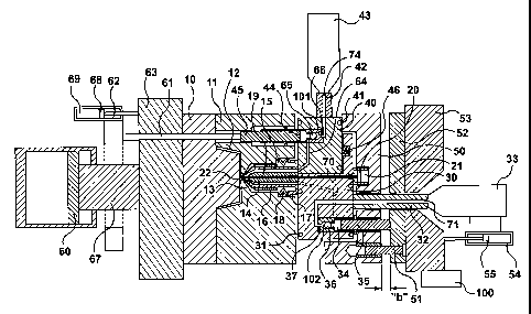
With reference to Figure 1, the mold includes a core block 10,
a cavity block 11 that together form a mold cavity 12. A
coinjection hot runner nozzle 13 includes a first melt channel
14 for conveying a resin "A", and a second melt channel 15 for
conveying a resin "C". The nozzle is maintained at operating
temperature by a heater 16, is located in the cavity block 11
by a locating insulator 17, and is urged in sealing contact
with the manifolds by a spring pack 18. The nozzle 13 also
contains a valve stem 19 that is actuated by a piston 20 in a
cylinder 21 to open and close a gate 22 that connects melt the
channels 14 and 15 to the mold cavity 12.
The mold has two hot runner manifolds. A first hot runner
manifold 30 handles the resin "A" and is maintained at optimum
operating temperature for the resin "A" by heaters 31.
Attached to the first hot runner manifold 30 is a first sprue
32 that conveys the resin "A" from a first machine injection
unit 33. Also attached to the first hot runner manifold 30 is
a first shooting pot 34 that contains a first shooting pot
piston 35. A second hot runner manifold 40 handles the resin
"C" and is maintained at optimum operating temperature for the
resin "C" by heaters 41. Attached to the second hot runner
6
CA 02567538 2006-11-21
WO 2006/002515 PCT/CA2005/000845
manifold 40 is a second sprue 42 that conveys the resin "C"
from a second machine injection unit 43. Also attached to the
second hot runner manifold 40 is a second shooting pot 44 that
contains a second shooting pot piston 45. The second hot
runner manifold 40 is spaced away from the first hot runner
manifold 30, urged by a compensation element 46, to allow the
combined first and second manifold configuration to handle the
thermal expansion of the components.
Both the first hot runner manifold 30 and the second hot runner
manifold 40 are located in a manifold plate 50 that is coupled
to the cavity block 11 by fastening means such as bolts (not
shown). Both of the manifolds 30 and 40 seal against the
nozzle 13 such that their respective melt channels align and
seal with their counterpart channels in the nozzle 13 to convey
resins "A" and "C", respectively, from the shooting pots 34 and
44 to the mold cavity 12 when the valve stem 19 is open and the
respective shooting pot pistons 35 and 45 are actuated.
The manifold plate 50 is located and guided on guide pins 51
mounted in a manifold backing plate 52 that is fastened to a
machine stationary platen 53. When the first injection unit 33
charges the first shooting pot 34 with the resin "A", the entry
of the resin into the shooting pot displaces the
manifold/cavity block assembly away from the manifold backing
plate 52 a distance of "b", as shown in Figure 1. The
actuation of a machine clamp piston 60 via a column 67 (that is
attached to a moving platen 63) causes the mold assembly to
move towards the stationary platen 53, thereby collapsing the
distance "b" and causing the first shooting pot piston 35
(which is fixedly coupled to the manifold backing plate 52
and/or the stationary platen 53) to inject the resin "A" from
the first shooting pot 34, through a first hot runner melt
channel 70, into the first melt channel 14 in the nozzle 13 and
thereby into the mold cavity 12. A first ball check valve 36
in a first feed channel 37 prevents backflow of the injected
resin into the first injection unit 33. The first injection
unit 33 is maintained in sealing contact with the first sprue
32 during these movements of the manifolds and cavity block by
means of a first cylinder 54 coupled to the first injection
7
CA 02567538 2006-11-21
WO 2006/002515 PCT/CA2005/000845
unit 33 and a first piston 55 that is connected to the
stationary platen 53.
The second shooting pot piston 45 is actuated by a rod 61 that
is connected to a plate 62, which is mounted behind the
machine's moving platen 63 and is moved by a second piston 68
disposed in a second cylinder 69. When the second injection
unit 43 charges the second shooting pot 44 with the resin "C",
the entry of the resin into the shooting pot displaces the
second shooting pot piston 45 away from the second hot runner
manifold 40 until it contacts the rod 61 that has been position
by the plate 62 at the predetermined shot size for resin "C".
The forward movement of the plate 62 causes the rod 61 to
advance the second shooting pot piston 45 and discharge the
resin "C from the second shooting pot 44 via a second hot
runner channel 64 in the manifold 40, the second melt channel
15 in nozzle 13, and into the mold cavity 12 via the open valve
gate 22. A second ball check valve 65 in a second feed channel
66 prevents backflow of the injected resin into the second
injection unit 43. The second injection unit 43 is mounted
atop the mold assembly and travels with movable section of the
mold, thereby maintaining its sealing contact with the second
sprue 42 throughout the molding cycle.
The check valves 36 and 65 preferably use a ball as an
occlusion that travels within a check valve chamber having a
longitudinal length at least twice as long as the diameter of
the ball occlusion. In an alternative embodiment, the check
valve chamber length may be equal to or greater than three
times the ball diameter, most preferably the chamber length is
approximately two times the ball diameter. Since the ball now
travels an extended length in the lengthened check valve
chamber, this provides some decompression to the resin in the
corresponding hot runner melt channel without reducing the shot
size within the corresponding shooting pot. In this
alternative embodiment, it is preferable that the ball diameter
closely match the internal diameter of the check valve chamber
to shut off any resin flow around the ball.
8
CA 02567538 2006-11-21
WO 2006/002515 PCT/CA2005/000845
In a further alternative embodiment, the check valve occlusion
may have a shape other than a ball, in order to provide
enhanced resin flow control. For example, the occlusion may
comprise a cylinder having one or more conical ends. Or, the
occlusion may have an aerodynamic, streamlined shape configured
to cooperate with corresponding shapes in the check valve
chamber to accomplish precise flow control of the resin. Such
occlusions may have one or more longitudinal slots disposed
therein to allow passage of resin thereby, under certain
circumstances, to provide even more precise flow/pressure
control of the resin. These alternative "torpedo" shapes may be
used for differential and/or variable pressure control over the
resin flowing therethrough. For example, the torpedo may be
designed to have a differential pressure across the length
thereof.
To control the movements of the various machine elements (e.g.,
the first and second injection units 33, 43, the clamp piston
60, the plate 62, the second piston and cylinder 68, 69, etc.),
any type of controller or processor 100 may be used to control
various known actuators (not shown). For example, one or more
general-purpose computers, Application Specific Integrated
Circuits (ASICs), Digital Signal Processors (DSPs), gate
arrays, analog circuits, dedicated digital and/or analog
processors, hard-wired circuits, etc., may receive input and
provide output to the various controllable components described
herein. Instructions for controlling the one or more of such
controllers or processors may be stored in any desirable
computer-readable medium and/or data structure, such floppy
diskettes, hard drives, CD-ROMs, RAMs, EEPROMs, magnetic
media, optical media, magneto-optical media, etc.
3. The Process of the First Embodiment
In operation, the molding cycle starts with the configuration
shown in Figure 1; that is, both of shooting pots 34 and 44 are
charged with their respective resins, the valve gate 19 is
closed, and the mold core block 10 and the mold cavity block 11
are closed. Figure 2 shows the next step in the molding cycle.
The valve gate 19 has been opened by the valve stem piston 20,
the machine clamp piston 60 has been actuated to move the
9
CA 02567538 2006-11-21
WO 2006/002515 PCT/CA2005/000845
column 67, moving the moving platen 63, the mold core block 10,
the mold cavity block 11, and the manifold assembly toward the
stationary platen 53 until the distance "b" has been taken up.
This action displaces the first shooting pot piston 35 that
injects the resin "A" in the first shooting pot 34 into the
mold cavity 12 via the first hot runner melt channel 70, and
the first melt channel 14 in the nozzle 13. This metered first
shot of resin "A" at least partially fills the mold cavity 12.
Figure 3 shows the next step in the molding cycle. The plate
62 is actuated to push the rod 61 against the second shooting
pot piston 45, which injects the resin "C" in the second
shooting pot 44 into the mold cavity 12 via the second hot
runner melt channel 64 in the second hot runner manifold 40 and
the second melt channel 15 in the nozzle 13. This metered
second shot of resin "C" preferably flows within the earlier
metered shot of resin "A", pushing the resin "A" further along
the cavity and setting up a multilayered wall in the part, in
known fashion. The combined amounts of resin injected so far
preferably only partially fill the mold cavity 12.
The first injection unit 33 then injects a second shot of the
resin "A" (three shots of resin total) directly through a first
sprue melt channel 71 in the first sprue 32, the first check
valve feed channel 37 in the first shooting pot 34, thereby
pushing the ball in the first ball check valve 36 to its open
position, as shown. The second shot of resin "A" then travels
through the first hot runner melt channel 70 in the first hot
runner manifold 30, and finally via the first melt channel 14
in the nozzle 13 to fill and pack the mold cavity 12. Since
the mold is clamped closed by the clamp piston 60 at this time,
the pressure of the melt flowing through the first sprue melt
channel 71 acting on the shooting pot piston 35 cannot enter
the shooting pot 34 as the clamp force does not allow the
piston 35 to move.
The decompression feature according to the preferred embodiment
is shown in greater detail in Figure 4. The decompression step
preferably takes place after the third shot has been injected
and the packing stage has commenced. Of course, decompression
CA 02567538 2006-11-21
WO 2006/002515 PCT/CA2005/000845
can take place at any time and in any melt channel/shooting pot
combination, depending on the particular injection application.
Figure 4 shows the nozzle assembly 13 of the mold in Figure 1
at the next stage of the molding cycle, showing the valve stem
19 in the open positionand the resin "A" being pushed back
into the "C" resin melt channel 15 of the nozzle 13. This is
achieved by retracting the plate 62 to pull the rod 61 slightly
away (e.g. 1,0 mm) from the second shooting pot piston 45 to a
predetermined position called a "pre-pullback" position. The
pressurized resin in the "A" melt channel 14 of the nozzle 13,
that is packing the molded article via the open gate 22 at this
point in the molding cycle, causes a small amount of the distal
portion of the "A" resin to bleed from the distal end of the
first melt channel 14 and/or from the cavity 12 and/or from the
gate 22, into the "C" melt channel 15 in the nozzle 13, until
the pressure in the "C" shooting pot balances the "A" resin
packing pressure. Thus, the distal portion of the "C" resin
moves upward and away from the distal end of the second melt
channel 15, preventing significant amounts of the "C" resin
from entering the mold cavity when the next shot of the "A"
resin is injected.
During this decompression back-flow of resin "C", the "C" resin
ball check valve 65 prevents the "C" resin from back-flowing
into the "C" injector unit 43, and consequently the "C"
shooting pot piston 45 moves back until it contacts the rod 61
held by the plate 62 in this "pre-pullback" position. By
allowing a small amount of "A" resin to enter the "C" channel
15 in the nozzle 13, at the beginning of the next molding cycle
(when the first shot of "A" resin is injected) no "C" resin
will bleed into that first shot. This is advantageous since
the first shot of "A" resin should not be contaminated with any
"C" resin; otherwise the molded article may have layers with
gaps or holes therein, producing a defective part. The
presence of a small amount of "A" resin in the "C" resin nozzle
melt channel is not disadvantageous since the next shot of "C"
resin will be injected into a mold cavity already containing
the first shot of "A" resin.
11
CA 02567538 2006-11-21
WO 2006/002515 PCT/CA2005/000845
Figure 5 shows the next stage of the molding cycle where, after
a brief interval of packing pressure maintained by the first
injection unit 33, the valve stem 19 is closed by the piston
20, and the molded part continues to cool.
Figure 6 shows the next step in the molding cycle. During the
cooling of the molded article or part, the shot size for the
"C" shooting pot 44 is set by further retracting the rod 61 to
a predetermined "pull back" position. This is done by the
second piston 68 operating in the second cylinder 69 to retract
the plate 62 to the predetermined position. As the molded part
continues to cool, the second shooting pot 44 is recharged with
the resin "C" by the second injector 43 feeding the resin "C"
through a second sprue melt channel 74. Because the valve stem
19 is in the closed position, the incoming resin "C" can only
flow into the second shooting pot 44, thereby displacing the
second shooting pot piston 45 until it contacts the rod 61 and
the plate 62, thereby limiting the shot size to a predetermined
size. A residual pressure remains in the second shooting pot
44 since its piston 45 is restrained from moving by the rod 61.
Alternatively, the refilling of the "C" shooting pot 44 can
take place simultaneously with the recharging of the "A" resin
shooting pot 34, since both manifolds 30 and 40 (and their
respective injection units 33 and 43) can be operated
independently. After the second shooting pot 44 is refilled,
the plate 62 is activated to continue to retract the rod 61, to
decompress the resin "C" in the second shooting pot 44, and so
that the distal end of rod 61 clears the cavity block 11, as
shown in Figure 7. This ensures that the rod 61 is not exposed
above the mold parting line when the mold is opened, as shown
in Figure 8.
Figure 7 shows that after a predetermined cooling period, the
clamp piston 60 is depressurized and the first shooting pot 34
is recharged with resin "A" by the first injection unit 33
feeding the resin "A" through the first check valve feed
channel 37. Because the valve stem 19 is in the closed
position, the incoming resin "A" can only flow into the first
shooting pot 34, thereby displacing the first shooting pot
piston 35 that, in turn, pushes the movable mold portion (core
12
CA 02567538 2006-11-21
WO 2006/002515 PCT/CA2005/000845
block 10, cavity block 11, manifolds 30 and 40, and manifold
plate 50) and the moving platen 63, away from the manifold
backing plate 52, creating space "b", as shown in Figure 7.
The position of the clamp piston 60 is controlled to stop at a
predetermined position in order to set the shot si=ze for the
"A" shooting pot 34. Thus, when the incoming resin "A" has
filled the first shooting pot 34, a residual pressure remains
therein since the shooting pot cylinder has been restrained
from moving by the clamp piston 60. The "C" shooting pot, if
it has not already been refilled, can be refilled at the same
time as the refilling of the "A" shooting pot, as described
above as an alternate cycle event.
Figure 8 shows the final step in the molding cycle. The molded
part has cooled sufficiently to be ejected, so the mold is
opened, causing the resin "A" in the first shooting pot 34 to
decompress, and the molded part 73 is ejected off the core
block 10, in a conventional manner. Note that the rod 61 has
been retracted to clear the parting line so that a robot may
enter to pick up the ejected part, if necessary. Both of the
shooting pots 34 and 44 have been refilled and are ready for
injection when the mold closes to continue the cycle.
Figure 9 shows an alternate embodiment in which a"C" shooting
pot control plate 80 and its actuation means 81 (preferably a
piston and a cylinder, as shown) are configured within the mold
core half 10 of the mold. Also, a "C" resin injector unit 82
is mounted alongside the "A" resin injector unit 85 and
maintained in sealing contact with the "C" manifold sprue 83 by
cylinder means 84 throughout the molding cycle.
Figure 10 shows a sequence chart of events that represents the
complete molding cycle. As shown, the molding cycle begins
with the mold core 10 and mold cavity 11 closed and the
shooting pots 34 and 44 charged with their respective resins
"A" and "C". The space "b" is set between the movable hot
runner manifolds 30 and 40 and the manifold plate 50.
Thereafter, the valve stem 19 is opened, opening the gate 22.
The clamp piston 60 then presses the combined core block,
cavity block, and hot runner manifolds toward the manifold
13
CA 02567538 2006-11-21
WO 2006/002515 PCT/CA2005/000845
plate 50, injecting a metered shot of the resin "A" from the
first shooting pot 34 into the cavity 12. The clamp piston 64
applies clamp tonnage to ensure that a predetermined shot of
resin "A" is properly injected into the cavity 12. The piston
68 and cylinder 69 then drive the plate 62 and rod 61 so as to
discharge the resin "C" from the second shooting pot 44 into
the cavity 12. A second shot of resin "A" is injected by the
first injection unit 33 until the mold cavity is filled. The
first injection unit 33 then maintains a packing pressure
briefly. Preferably, the resin "C" is then decompressed by
rearward movement of the plate 62, as discussed above. That
is, the first injection unit 33 holds the injection pressure
while the piston 68 and the cylinder 69 retract the plate 62
and the rod 61, causing the second shooting pot piston 45 to
retract, allowing a small amount of the resin "A" to enter the
"C" resin melt channel 15 in the nozzle 13, as previously
described.
Then, the valve stem 19 is moved forward, closing the valve
gate 22. In this configuration, the molded part is cooled.
While the part is cooling, the plate 62 is retracted to a
predetermined position for the next metered shot of the "C"
resin. The second injection unit 43 then recharges the second
shooting pot 44 with the resin "C". The "C" resin shooting pot
44 is then decompressed, and the "C" injection unit 43 is
recovered. At any time during this process when the mold is
not being clamped, the "A" injection unit 33 refills the "A"
shooting pot 34, separating the hot runner manifolds 30 and 40
from the stationary platen 53 by the distance "b", as
previously described. The "A" shooting pot 34 may be
decompressed by manipulation of the distance "b", and the "A"
injection unit 33 is then recovered. Finally, the mold is
opened and the molded parts are ejected.
4. Conclusion
Advantageous features according to the present invention
include:
= A coinjection molding process in which one of the resins
flows in a reverse direction to enter the melt channel in
the nozzle assembly of one of the other resins.
14
CA 02567538 2006-11-21
PCT/CA2005/000845
January 2006 10-01-2006
H-7B6-0-W0
= A coinjection molding process in which at least one of the
shooting pots is decompressed after refilling and prior to
its discharge.
5 Thus, what has been described is a coinjection molding control
system which can relieve the pressure build up on resin between
the check valve and the valve gate during the molding cycle,
preventing injection of unwanted resin into the mold cavity.
10 The individual components shown in outline or designated by
blocks in the attached Drawings are all well-known in the
injection molding arts, and their specific construction and
operation are not critical to the operation or best mode for
carrying out the invention.
While the present invention has been described with respect to
what is presently considered to be the preferred embodiments,
it is to be understood that the invention is not limited to the
disclosed embodiments. To the contrary, the invention is
intended to cover various modifications and equivalent
arrangements included within the scope of the appended claims.
The scope of the following claims is to be accorded the
broadest interpretation so as to encompass all such
modifications and equivalent structures and functions.
AMLDIDED SHELT