Language selection

Search

Patent 2567577 Summary

Third-party information liability

Some of the information on this Web page has been provided by external sources. The Government of Canada is not responsible for the accuracy, reliability or currency of the information supplied by external sources. Users wishing to rely upon this information should consult directly with the source of the information. Content provided by external sources is not subject to official languages, privacy and accessibility requirements.

Claims and Abstract availability

Any discrepancies in the text and image of the Claims and Abstract are due to differing posting times. Text of the Claims and Abstract are posted:

  • At the time the application is open to public inspection;
  • At the time of issue of the patent (grant).
(12) Patent: (11) CA 2567577
(54) English Title: METHOD OF TESTING A SEAL
(54) French Title: METHODE DE VERIFICATION D'UN SCELLEMENT
Status: Expired and beyond the Period of Reversal
Bibliographic Data
(51) International Patent Classification (IPC):
  • G01M 3/32 (2006.01)
(72) Inventors :
  • HAYES, JOSEPH P. (United States of America)
  • SCHARTNER, CARL B. (United States of America)
  • BRENNAN, WILLIAM D. (United States of America)
(73) Owners :
  • INTRAPAC INTERNATIONAL LLC
(71) Applicants :
  • INTRAPAC INTERNATIONAL LLC (United States of America)
(74) Agent: CRAIG WILSON AND COMPANY
(74) Associate agent:
(45) Issued: 2011-03-29
(22) Filed Date: 2006-11-10
(41) Open to Public Inspection: 2007-06-29
Examination requested: 2008-07-28
Availability of licence: N/A
Dedicated to the Public: N/A
(25) Language of filing: English

Patent Cooperation Treaty (PCT): No

(30) Application Priority Data:
Application No. Country/Territory Date
11/323,518 (United States of America) 2005-12-29

Abstracts

English Abstract

The present invention is for a method of testing a seal on a collapsible tube dispensing orifice during the manufacturing process. Air pressure is applied on one side of the seal, and the pressure is monitored on the other side of the seal, for any increase in pressure which would indicate a leak in the seal.


French Abstract

La présente invention concerne une méthode d'essai d'un scellement sur un orifice de distribution à tube rétractable lors du processus de fabrication. Une pression d'air est appliquée sur un côté du scellement, et est surveillée de l'autre côté du scellement; toute augmentation de pression décelée indiquerait une fuite dans le scellement.

Claims

Note: Claims are shown in the official language in which they were submitted.

THE EMBODIMENTS OF THE INVENTION IN WHICH AN EXCLUSIVE
PROPERTY OR PRIVILEGE IS CLAIMED ARE DEFINED AS FOLLOWS:
1. In the manufacture, through successive stations of an assembly
line, of an empty open bottom collapsible tube having a tube wall
secured to a head, a dispensing orifice in the head, a seal on the
orifice, and a closure cap applied over the orifice, the
improvement comprising:
a method of testing the seal for leaks at a separate station in
the assembly line, after the seal is applied, but before the
closure cap is applied on the orifice, by
(1) temporarily closing the open bottom with a stopper;
(2) maintaining air under pressure inside the tube wall; and
(3) determining whether any air passes through the seal by
monitoring the pressure on an opposite side of the seal, within a
cover that forms an airtight joint with the head.
7

Description

Note: Descriptions are shown in the official language in which they were submitted.


CA 02567577 2006-11-10
08435P0035CA01
METHOD OF TESTING A SEAL,
BACKGROUND OF THE INVENTION
(1) Field of the Invention
This invention relates generally to a collapsible tube
used to contain and dispense fluids, and particularly to a
seal on the dispensing orifice of such a tube.
(2) The Prior Art
Collapsible tubes are packages in tube form having a
dispensing orifice at one end of a deformable tube. The
tube is deformed and collapsed by squeezing so that the
contents are forced out of the orifice.. Such tubes are
used to contain toothpaste, pharmaceuticals, cosmetics,
personal care products, artists' pigments, adhesives,
sealants and caulking materials, greases and lubricants,
foods and condiments, and many other products. A
collapsible tube generally has a screw closure cap.
Such tubes are made of metal, such as lead, tin and
aluminum, or of plastic or laminate materials.
Collapsible tubes often have a seal across the
dispensing orifice of the tube, particularly when used for
medicinal products. The seal prevents the tube contents
from leaking out prior to use. Also, the seal prevents any
atmospheric contact with the tube contents, since the tube
is sealed in an air-tight manner.
1

CA 02567577 2010-10-22
In use, the seal is pierced by, for instance, a point
formed in the tube screw cap.
A method of forming a seal on a collapsible tube is shown
in U.S. Patent 4,938,818.
This invention is specifically directed to a method of
testing such a seal for leaks.
SUMMARY OF THE PRESENT INVENTION
The present invention as seen in the drawings, provides a
method of testing the seal on a collapsible tube during the
manufacturing process, wherein tube components that include a
head 21 with a dispensing orifice, a tube wall 22 that is
secured to the head 21, a seal 35 that is applied over the
dispensing orifice, and a screw closure cap 37, are all, at
stations, assembled into the completed tube 118. The tube wall
22 is left open at the bottom for subsequent filling and
closing.
In the present invention, in testing for a seal 35 that
leaks, air under pressure is applied to one side of the seal
35, at a station 201 in the manufacturing process of the tube,
and any increase in pressure on the opposite side of the seal
35 is noted.
Such pressure increase indicates a seal 35 that is
defective and leaks.
2

CA 02567577 2010-10-22
According to one aspect of the present invention, there
is provided in the manufacture, through successive stations of
an assembly line, of an empty open bottom collapsible tube
having a tube wall secured to a head, a dispensing orifice in
the head, a seal on the orifice, and a closure cap applied
over the orifice, the improvement comprising:
a method of testing the seal for leaks at a separate station
in the assembly line, after the seal is applied, but before
the closure cap is applied on the orifice, by
(1) temporarily closing the open bottom with a stopper;
(2) maintaining air under pressure inside the tube wall; and
(3) determining whether any air passes through the seal by
monitoring the pressure on an opposite side of the seal,
within a cover that forms an airtight joint with the head.
20
2a

CA 02567577 2006-11-10
BRIEF DESCRIPTION OF THE DRAWINGS
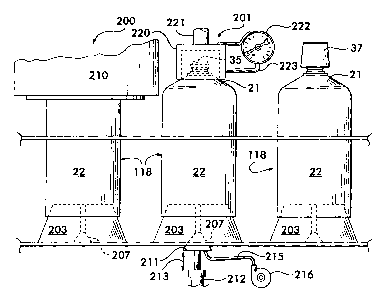
Figure 1 is a schematic side elevational view of
successive stations in the manufacturing process that
includes a station 201 that tests a seal for leaks, in
accordance with the present invention.. The station that
tests for leaks is installed between stations in the
manufacture of the tube. Such stations in the manufacture
of the tube are shown in Figure 7 of the '818 patent-
Figure 2 is an enlarged view of the testing station of
the invention shown at 201 in Figure 1_
DESCRIPTION OF THE PREFERRED EMBODIMENT
The Prior Art
In the '818 patent referred to above, a seal disc is
bonded to the dispensing orifice on the head of a
collapsible tube, and the head of the tube is bonded to a
preformed tube wall, by radio frequency..
After applying a closure cap to the threaded neck of
the head, the open bottomed tube is ready to be shipped to
a purchaser for filling through the tube open bottom, after
which the tube is closed at the bottom.
The Improvement
In present invention, as seen in Figure 1, a seal 35
bonded to the dispensing orifice of a head 21 of
collapsible tube 118 is tested for leaks at a testing
3

CA 02567577 2006-11-10
station 201, which is positioned between stations of a
prior art tube manufacturing line, as disclosed in the '818
patent. The tube is formed at station 200 (designated
station 90 in the '818 patent) in accordance with the
disclosure of the '818 patent, where a movable,
reciprocating, power-driven cap 210 bonds the seal 35 to
the dispensing orifice of head 21, and tube wall 22 to the
head 21, with radio frequency waves..
Cap 210 reciprocates horizontally, and tube 118, on
mandrel 203 is indexed to station 201, where the testing
for leaks occurs. The vacuum that has been applied at
station .200, in accordance with the prior art teaching of
the '818 patent, is turned off before indexing to station
201.. At station 201, stopper 211 is moved upward into
cavity 207 of mandrel 203 by hydraulic plunger 212, the
shaft of which reciprocates vertically as shown at 213.
Flexible hose 215 is connected to a regulated and valve
activated compressed air pump 216 which provides air under
pressure at, for instance, 40 pounds per square inch, to
the interior of collapsible tube 118. The air pressure is
such that the seal 35 can retain the pressure without
bursting.
4

CA 02567577 2006-11-10
The stopper 211 and cavity 207 in mandrel 203 each
desirably have a soft surface so they can readily form a
tight force fit during the testing.
Simultaneously with movement of stopper 211 into
position at the bottom of the tube 118 at station 201, a
top cover 220, as seen at station 201 in Figures 1 and 2 of
the present drawings, moves downward at the end of
vertically reciprocating shaft 221, to cover seal 35, and
to make contact with head 21. Cover 220 forms an airtight
joint with head 21..
A pressure sensor 222 is supported from cover 220,
with conduit 223 connected to the interior of cover 220..
In operation, during the manufacturing of the tubes
118, the tubes 118 to be tested are intermittently moved
into station 201, where cover 220 is moved into contact
with head 21, forming an airtight compartment over the seal
35 and head 21. Simultaneously, at station 201, stopper
211 is inserted upwardly into cavity 207 and air at a given
pressure enters tube neck 30. If the seal 35 is tight with
no leaks, air under pressure is maintained inside the tube
118, and no air leaks through the seal..
In the event of a leak in the seal 35, air escapes up
into cover 220, and the pressure within cover 220 builds up
and is detected by the pressure sensor 222. The tube 118
5

CA 02567577 2006-11-10
with the defective seal 35 is automatically removed from
the assembly line to a discharge conveyor and scrapped.
Generally, there is no leakage through the seal 35,
and the tube will pass to station 202, where, as in the
prior art, a closure cap 32 is applied to the completed
tube 118 by rotating the closure cap 32 onto the threads of
the neck of head 21..
15
6

Representative Drawing
A single figure which represents the drawing illustrating the invention.
Administrative Status

2024-08-01:As part of the Next Generation Patents (NGP) transition, the Canadian Patents Database (CPD) now contains a more detailed Event History, which replicates the Event Log of our new back-office solution.

Please note that "Inactive:" events refers to events no longer in use in our new back-office solution.

For a clearer understanding of the status of the application/patent presented on this page, the site Disclaimer , as well as the definitions for Patent , Event History , Maintenance Fee  and Payment History  should be consulted.

Event History

Description Date
Time Limit for Reversal Expired 2022-05-10
Letter Sent 2021-11-10
Letter Sent 2021-05-10
Letter Sent 2020-11-10
Common Representative Appointed 2019-10-30
Letter Sent 2019-02-25
Inactive: Single transfer 2019-02-12
Letter Sent 2019-01-23
Inactive: Office letter 2019-01-23
Letter Sent 2019-01-23
Inactive: Single transfer 2019-01-15
Appointment of Agent Request 2018-06-06
Revocation of Agent Request 2018-06-06
Letter Sent 2018-01-23
Inactive: Office letter 2017-12-15
Letter Sent 2017-12-15
Letter Sent 2017-12-13
Inactive: Single transfer 2017-12-11
Inactive: Single transfer 2017-12-08
Letter Sent 2015-09-08
Revocation of Agent Requirements Determined Compliant 2014-09-11
Inactive: Office letter 2014-09-11
Appointment of Agent Requirements Determined Compliant 2014-09-11
Change of Address or Method of Correspondence Request Received 2014-09-02
Appointment of Agent Request 2014-09-02
Revocation of Agent Request 2014-09-02
Letter Sent 2012-01-23
Grant by Issuance 2011-03-29
Inactive: Cover page published 2011-03-28
Inactive: Final fee received 2011-01-11
Pre-grant 2011-01-11
Notice of Allowance is Issued 2010-11-08
Letter Sent 2010-11-08
Notice of Allowance is Issued 2010-11-08
Inactive: Approved for allowance (AFA) 2010-11-02
Amendment Received - Voluntary Amendment 2010-10-22
Inactive: S.30(2) Rules - Examiner requisition 2010-05-05
Letter Sent 2008-09-23
Request for Examination Received 2008-07-28
Request for Examination Requirements Determined Compliant 2008-07-28
All Requirements for Examination Determined Compliant 2008-07-28
Application Published (Open to Public Inspection) 2007-06-29
Inactive: Cover page published 2007-06-28
Inactive: Acknowledgment of s.8 Act correction 2007-04-19
Inactive: Applicant deleted 2007-04-05
Inactive: S.8 Act correction requested 2007-03-15
Inactive: First IPC assigned 2007-02-05
Inactive: IPC assigned 2007-02-05
Application Received - Regular National 2006-12-13
Inactive: Filing certificate - No RFE (English) 2006-12-13
Filing Requirements Determined Compliant 2006-12-13
Letter Sent 2006-12-13

Abandonment History

There is no abandonment history.

Maintenance Fee

The last payment was received on 2010-09-16

Note : If the full payment has not been received on or before the date indicated, a further fee may be required which may be one of the following

  • the reinstatement fee;
  • the late payment fee; or
  • additional fee to reverse deemed expiry.

Please refer to the CIPO Patent Fees web page to see all current fee amounts.

Owners on Record

Note: Records showing the ownership history in alphabetical order.

Current Owners on Record
INTRAPAC INTERNATIONAL LLC
Past Owners on Record
CARL B. SCHARTNER
JOSEPH P. HAYES
WILLIAM D. BRENNAN
Past Owners that do not appear in the "Owners on Record" listing will appear in other documentation within the application.
Documents

To view selected files, please enter reCAPTCHA code :


To view images, click a link in the Document Description column. To download the documents, select one or more checkboxes in the first column and then click the "Download Selected in PDF format (Zip Archive)" or the "Download Selected as Single PDF" button.

List of published and non-published patent-specific documents on the CPD .

If you have any difficulty accessing content, you can call the Client Service Centre at 1-866-997-1936 or send them an e-mail at CIPO Client Service Centre.


Document
Description 
Date
(yyyy-mm-dd) 
Number of pages   Size of Image (KB) 
Abstract 2006-11-10 1 10
Description 2006-11-10 6 168
Drawings 2006-11-10 2 48
Claims 2006-11-10 1 24
Representative drawing 2007-06-01 1 12
Cover Page 2007-06-22 1 34
Description 2010-10-22 7 188
Claims 2010-10-22 1 21
Cover Page 2011-03-02 1 35
Courtesy - Certificate of registration (related document(s)) 2006-12-13 1 106
Filing Certificate (English) 2006-12-13 1 158
Courtesy - Certificate of registration (related document(s)) 2006-12-13 1 105
Reminder of maintenance fee due 2008-07-14 1 114
Acknowledgement of Request for Examination 2008-09-23 1 176
Commissioner's Notice - Application Found Allowable 2010-11-08 1 163
Courtesy - Certificate of registration (related document(s)) 2017-12-15 1 106
Courtesy - Certificate of registration (related document(s)) 2017-12-13 1 106
Courtesy - Certificate of registration (related document(s)) 2018-01-23 1 106
Courtesy - Certificate of registration (related document(s)) 2019-01-23 1 106
Courtesy - Certificate of registration (related document(s)) 2019-02-25 1 106
Commissioner's Notice - Maintenance Fee for a Patent Not Paid 2020-12-29 1 544
Courtesy - Patent Term Deemed Expired 2021-05-31 1 551
Commissioner's Notice - Maintenance Fee for a Patent Not Paid 2021-12-22 1 542
Correspondence 2007-03-15 6 188
Correspondence 2011-01-11 2 49
Correspondence 2014-09-02 3 72
Correspondence 2014-09-11 1 22
Correspondence 2014-09-11 1 25
Courtesy - Office Letter 2017-12-15 1 47
Courtesy - Office Letter 2019-01-23 1 52