Language selection

Search

Patent 2568147 Summary

Third-party information liability

Some of the information on this Web page has been provided by external sources. The Government of Canada is not responsible for the accuracy, reliability or currency of the information supplied by external sources. Users wishing to rely upon this information should consult directly with the source of the information. Content provided by external sources is not subject to official languages, privacy and accessibility requirements.

Claims and Abstract availability

Any discrepancies in the text and image of the Claims and Abstract are due to differing posting times. Text of the Claims and Abstract are posted:

  • At the time the application is open to public inspection;
  • At the time of issue of the patent (grant).
(12) Patent: (11) CA 2568147
(54) English Title: DEVICE FOR AUTOMATIC DETECTION OF BATTERY POLARITY
(54) French Title: DISPOSITIF POUR LA DETECTION AUTOMATIQUE DE LA POLARITE D'ACCUMULATEUR
Status: Expired and beyond the Period of Reversal
Bibliographic Data
(51) International Patent Classification (IPC):
  • G01R 31/364 (2019.01)
  • H02J 07/00 (2006.01)
(72) Inventors :
  • CHANG, I-CHANG (Taiwan, Province of China)
(73) Owners :
  • JYE CHUANG ELECTRONIC CO., LTD.
(71) Applicants :
  • JYE CHUANG ELECTRONIC CO., LTD. (Taiwan, Province of China)
(74) Agent: ADE & COMPANY INC.
(74) Associate agent:
(45) Issued: 2010-03-23
(22) Filed Date: 2006-11-09
(41) Open to Public Inspection: 2008-05-09
Examination requested: 2006-11-09
Availability of licence: N/A
Dedicated to the Public: N/A
(25) Language of filing: English

Patent Cooperation Treaty (PCT): No

(30) Application Priority Data: None

Abstracts

English Abstract

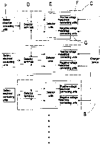
The present invention provides a device for automatic detection of battery polarity, wherein detector circuits are structured from detector terminals, detector units, positive voltage electrical connecting units and negative voltage electrical connecting units. Operational procedure involves first connecting battery electrical conducting units with the detector terminals of the detector circuits, when the detector terminals are connected to positive poles of a battery, then one set or more than one set of the detector units of the detector circuits detect positive voltage, which actuate an electrical connection with the positive voltage electrical connecting units, thus connecting positive poles of the detector device to the detector terminals and connecting to positive poles of the battery, at the same time one set or more than one set of the detector units determine negative voltage and actuate a connection with the negative voltage electrical connecting units, thereby forming a complete circuit.


French Abstract

Enter the French Abstract hLa présente invention concerne un dispositif pour la détection automatique de la polarité d'accumulateur. Les circuits du détecteur sont composés de terminaux de détection, d'unités de détection, d'unités de connexion électrique de tension positive et d'unités de connexion électrique de tension négative. Un procédé d'utilisation consiste d'abord à brancher les unités conductrices électriques de l'accumulateur aux terminaux de détection des circuits de détection; lorsque les terminaux de détection sont branchés aux pôles positifs de l'accumulateur, une ou plusieurs séries d'unités de détection des circuits de détection détectent la tension positive, ce qui déclenche une connexion électrique avec les unités de connexion électrique de tension positive, branchant ainsi les pôles positifs du dispositif de détection aux terminaux de détection et aux pôles positifs de l'accumulateur. En même temps, une ou plusieurs séries d'unités de détection déterminent la tension négative et déclenchent une connexion avec les unités de connexion électrique de tension négative, formant ainsi un circuit complet.

Claims

Note: Claims are shown in the official language in which they were submitted.


What is claimed is:
1. A device for automatic detection of battery polarity, comprising a
plurality of detector terminals, a plurality of detector units, a plurality of
positive voltage electrical connecting units and a plurality of negative
voltage electrical connecting units,
wherein operational procedure involves first connecting
battery electrical conducting units with the plurality of detector
terminals, when the detector terminals are connected to positive poles
of the battery, then one set or more than one set of the detector units
detect positive voltage, which actuate an electrical connection with the
positive voltage electrical connecting units, at the same time one set
or more than one set of the detector units determine negative voltage
and actuate the negative voltage electrical connecting units, thereby
forming a complete circuit and enabling current to flow from the
positive voltage electrical connecting units,
wherein the plurality of detector terminals is more than two
and a detector circuitry of the detector units being configured so that
connecting the battery to any two of the plurality of detector terminals
enables the detector circuitry to form the complete circuit.
2. The device for automatic detection of battery polarity according to
-10-

claim 1, wherein control circuit members of the detector units are
transistors, comparators, optical couplers, SCR (semiconductor
controlled rectifiers), MOS (metal oxide semiconductors) and related
equivalent members.
3. The device for automatic detection of battery polarity according to
claim 1, wherein the positive voltage electrical connecting units and
the negative voltage electrical connecting units are MOS (metal oxide
semiconductors), relays, transistors, SCR (semiconductor controlled
rectifiers) and semiconductor members having related functionality.
4. The device for automatic detection of battery polarity according to
claim 1, wherein component members, including the plurality of sets of
detector units, the plurality of positive voltage electrical connecting
units, the plurality of negative voltage electrical connecting units, are
integrated to form a module and an integrated circuit (IC), thereby
effectively improving connectivity and operation of related circuits.
5. The device for automatic detection of battery polarity according to
claim 1, wherein the device is a charger device, a discharge device
and a device for measuring voltage, current, internal resistance or
related properties of a battery.
-11-

Description

Note: Descriptions are shown in the official language in which they were submitted.


CA 02568147 2006-11-09
DEVICE FOR AUTOMATIC DETECTION OF BATTERY POLARITY
BACKGROUND OF THE INVENTION
(a) Field of the Invention
The present invention relates to a device for automatic detection of
battery polarity, and more particularly to a device wherein positive
terminals and negative terminals of battery electrical connecting units
are respectively connected to detector terminals of detector circuits,
whereupon detector devices of the detector circuits actuate positive
voltage electricai connecting units and negative voltage electrical
connecting units, thereby enabling the detector circuits to form complete
circuits.
(b) Description of the Prior Art
FiC'~ 1 shows a charger A of prior art, wherein disposition of electrical
contact points Al of the charger A is fixed, and positive contact points
and negative contact points extending from a circuit located interior of
the charger A are fixed contact points. If a battery is disposed into the
charger A having a dissimilar configuration of positive and negative
contact points, then the charger A is unable to implement charging of
the battery, even to the extent of posing a threat of damaging the battery.
-1-

CA 02568147 2008-12-17
Furthermore, because of different sizes of batteries and position and
spacing of electrical contact points of chargers are all unequal, thus, the
single charger A is only able to singly accommodate the corresponding
battery A2, and is unable to achieve accommodating diverse batteries to
implement charging thereof.
In addition, positive and negative terminals of electrical connecting
terminal points of a conventional battery capacity check device are all
fixed. Hence, a capacity check device for the battery A2 is only able to
check the battery A2 corresponding to its electrical connecting terminal
points, and is unable to detect the battery A2 having contact points
located at different positions. Moreover, when using a power switching
unit, the conventional battery capacity check device is only able to
detect the single battery A2 having positive and negative terminal points
at fixed locations, and is unable to effectively accommodate the many
types of batteries A2 having contact points located at different positions.
SUMMARY OF THE INVENTION
One aspect of the present invention provides a device for automatic
detection of battery polarity, as depicted in FIGS. 2 and 3, wherein
detector circuits C are structured to comprise detector terminals D,
detector units E, positive voltage electrical connecting units F and
-2-

CA 02568147 2008-12-17
negative voltage electrical connecting units G.
Operational procedure for using the device involves first connecting
battery electrical conducting units H with the detector terminals D of the
detector circuits C. When the detector terminals D are connected to
positive poles of a battery B1, then one set or more than one set of
detector units E detect positive voltage, which actuate an electrical
connection with the positive voltage electrical connecting units F, and
positive poles of a charger device B are presented to the detector
terminals D and electrically connected to the positive poles of the
battery 61. Correspondingly, when the other detector terminals D are
connected to the battery B1, the remaining detector units E determine
that they are negative voltage and actuate the negative voltage
electrical connecting units G, then negative poles of the charger device
B are presented to the detector terminals D and electrically connected
to the negative poles of the battery BI, thereby forming a complete
charge circuit that enables the charger device B to commence charging
the battery B1.
According to another aspect of the invention there is provided a device
for automatic detection of battery polarity, comprising a plurality of
detector terminals, a plurality of detector units, a plurality of positive
-3-

CA 02568147 2008-12-17
voltage electrical connecting units and a plurality of negative voltage
electrical connecting units,
wherein operational procedure involves first connecting battery
electrical conducting units with the plurality of detector terminals, when
the detector terminals are connected to positive poles of the battery,
then one set or more than one set of the detector units detect positive
voltage, which actuate an electrical connection with the positive voltage
electrical connecting units, at the same time one set or more than one
set of the detector units determine negative voltage and actuate the
negative voltage electrical connecting units, thereby forming a complete
circuit and enabling current to flow from the positive voltage electrical
connecting units,
wherein the plurality of detector terminals is more than two and a
detector circuitry of the detector units being configured so that
connecting the battery to any two of the plurality of detector terminals
enables the detector circuitry to form the complete circuit.
To enable a further understanding of said objectives and the
technological methods of the invention herein, brief description of the
drawings is provided below followed by detailed description of the
-3a-

CA 02568147 2006-11-09
preferred embodiments.
BRIEF DESCRIPTION OF THE DRAWINGS
FlG 1 shows an elevational view of prior art.
FIG. 2 shows an elevational view according to the present invention.
FIG. 3 shows a system block diagram according to the present
invention.
FIG. 4 shows a circuit diagram according to the present invention.
FIG. 5 shows a circuit diagram according the present invention.
FIG. 6 shows an elevational view of an embodiment according to the
to present invention.
DETAILED DESCRIPTION OF THE PREFERRED EMBODIMENTS
Referring to FIGS. 3, 4, 5 and 6, which show an embodiment of a
device for automatic detection of battery pofarity of the present invention,
wherein when battery electrical conducting units H are connected to
detector terminals D of detector circuits C, then positive terminals H 1
and negative terminals H2 of the battery electric conducting units H
need only electrically connect to any two terminals of the detector
terminals D to enable the detector circuits C to form a complete charge
circuit. Moreover, a comparator El of each detector unit E detects the
positive terminals HI and the negative terminals H2 of each of the
-4-

CA 02568147 2006-11-09
battery electrical conducting units H, and the comparators El output
positive voltage to the positive terminals HI and negative voltage to the
negative terminals H2, thereby facilitating the detector circuits C in
forming a complete charge circuit.
A charger I uses two or more than two detector terminals D to enable
accommodating batteries B1 of different sizes and match different
positions and spacings of the battery electrical conducting units H,
thereby achieving electrical connections with all charge contact points of
the battery B1, and enabling the charger I to accommodate the different
types of battery B1 and correctly locate the positive terminals H1 and
the negative terminals H2 of the battery electrical connecting units H.
If detector terminal A points Dl are electrically connected to the
positive terminals H 9 of the battery electrical conducting units H, then
positive potential passes through the detector units E, which detect and
output positive voltage that enables electrical connecting with the
positive voltage electrical connecting units F, thus, the positive voltage
electrical connecting units F enable electrically connecting positive
poles of the charger device B to the detector terminal A points D1,
thereby enabling the positive poles of the charger device B to connect to
the positive terminafs H1 of the battery electrical conducting units H.
-5-

CA 02568147 2006-11-09
Correspondingly, detector terminal B points D2 are eiectricaiiy
connected to the negative terminals H2 of the battery electrical
conducting units H, and negative potential passes through the detector
units E, which detect and output negative voltage that enables electrical
connecting with the negative voltage electrical connecting units G, thus,
the negative voltage electrical connecting units G enable efectricaily
connecting negative poles of the charger device B to the detector
terminal B points D2, thereby enabling the negative poles of the charger
device B to connect to the negative terminals H2 of the battery etectricat
conducting units H, and enabling the charger device B to commence
charging of the battery 81.
Conversely, if the detector terminal A points D1 are electrically
connected to the negative terminals H2 of the battery electrical
conducting units H, then negative potential passes through the detector
I S units E, which detect and output negative voltage that enables electrical
connecting with the negative voltage electricai connecting units a thus,
the negative voltage electrical conneeting units G enable electricaiiy
connecting the negative poles of the charger device B to the detector
terminal A points Dl, thereby enabling the negative poles of the charger
device B to connect to the negative terminals H2 of the battery electrical
-s.

CA 02568147 2006-11-09
conducting units H. Correspondingly, detector terminal B points D2 are
electrically connected to the positive terminals H 9 of the battery
electrical conducting units H, and positive potential passes through the
detector units E, which detect and output positive voltage that enables
electrical connecting with the positive voltage eiectricai connecting units
F, thus, the positive voltage electrical connecting units F enable
electrically connecting the positive poles of the charger device B to the
detector terminal B points D2, thereby enabling the positive poles of the
charger device B to connect to the positive terminals H1 of the battery
electrical conducting units H, and enabling the charger device B to
commence charging of the battery B1.
If detector terminal C points D3 are not electricaliy connected to the
positive terminals HI nor to the negaiive terminals H2 of the battery
electrical conducting units H, then the detector units E detect and output
zero voltage, and the zero voltage is unable is effect electrical
connection with the positive voltage electricai connecting units F and the
negative voltage electrical connecting units G, thus, a charge circuit is
unable to be formed.
Control elements of the detector units E can be further configured as
transistors, comparators, optical couplers, SCR (semiconductor
-7-

CA 02568147 2006-11-09
controlled rectifiers), MOS (metal oxide semiconductors) and related
equivalent elements. The positive voltage electrical connecting units F
and the negative voltage electrical connecting units G can be configured
as semiconductor elements having a switching function, including MOS,
relays, transistors, SCR, and so on.
Integration of the plurality of sets of detector units E, the plurality of
sets of pQsitive voltage electrical connecting units F and the plurality of
sets of negative voltage electrical connecting units G form a module and
integrated circuit (IC), which efFectively improves connectivity and
operation of related electric circuits. Moreover, the detector circuits C
can serve as a device able to measure voltage, current, internal
impedance or related properties of a battery.
In order to better explicitly disclose advancement and practicability of
the present invention, advantages of the present invention are
described hereinafter:
1. When connecting pins of a battery are electrically connected to the
charger I, the charger I is able to automatically detect polarity of the
battery.
2. Power supply status of connecting pins of the charger I is
determined by electrical connecting positions of the battery.
-8-

CA 02568147 2006-11-09
3. Only requires electrical connection of the connecting pins of the
charger, and is not limited by size of the battery or position and spacing
of contact points of the battery.
4, Substantially increases compatibility of the charger I with batteries.
5. Provided with industriai competitiveness,
6. Provided with commercial utility value.
7. Provided with originality.
In conclusion, practicability and advancement of the present invention
clearly comply with essential elements as required for a new patent
application. Accordingly, a new patent application is proposed herein.
It is of course to be understood that the embodiments described
herein are merely illustrative of the principles of the invention and that a
wide variety of modifications thereto may be effected by persons skilled
in the art without departing from the spirit and scope of the invention as
set forth in the following claims.
-9-

Representative Drawing
A single figure which represents the drawing illustrating the invention.
Administrative Status

2024-08-01:As part of the Next Generation Patents (NGP) transition, the Canadian Patents Database (CPD) now contains a more detailed Event History, which replicates the Event Log of our new back-office solution.

Please note that "Inactive:" events refers to events no longer in use in our new back-office solution.

For a clearer understanding of the status of the application/patent presented on this page, the site Disclaimer , as well as the definitions for Patent , Event History , Maintenance Fee  and Payment History  should be consulted.

Event History

Description Date
Inactive: First IPC assigned 2021-08-17
Inactive: IPC assigned 2021-08-16
Inactive: IPC expired 2019-01-01
Inactive: IPC removed 2018-12-31
Time Limit for Reversal Expired 2015-11-09
Letter Sent 2014-11-10
Inactive: Late MF processed 2014-05-05
Letter Sent 2013-11-12
Inactive: Agents merged 2012-03-07
Grant by Issuance 2010-03-23
Inactive: Cover page published 2010-03-22
Pre-grant 2009-12-09
Inactive: Final fee received 2009-12-09
Notice of Allowance is Issued 2009-06-25
Letter Sent 2009-06-25
Inactive: Approved for allowance (AFA) 2009-06-22
Amendment Received - Voluntary Amendment 2008-12-17
Inactive: S.30(2) Rules - Examiner requisition 2008-06-26
Inactive: S.29 Rules - Examiner requisition 2008-06-26
Application Published (Open to Public Inspection) 2008-05-09
Inactive: Cover page published 2008-05-08
Inactive: First IPC assigned 2007-02-23
Inactive: IPC assigned 2007-02-23
Inactive: Filing certificate - RFE (English) 2006-12-19
Letter Sent 2006-12-19
Application Received - Regular National 2006-12-19
All Requirements for Examination Determined Compliant 2006-11-09
Small Entity Declaration Determined Compliant 2006-11-09
Request for Examination Requirements Determined Compliant 2006-11-09

Abandonment History

There is no abandonment history.

Maintenance Fee

The last payment was received on 2009-11-02

Note : If the full payment has not been received on or before the date indicated, a further fee may be required which may be one of the following

  • the reinstatement fee;
  • the late payment fee; or
  • additional fee to reverse deemed expiry.

Patent fees are adjusted on the 1st of January every year. The amounts above are the current amounts if received by December 31 of the current year.
Please refer to the CIPO Patent Fees web page to see all current fee amounts.

Fee History

Fee Type Anniversary Year Due Date Paid Date
Registration of a document 2006-11-09
Application fee - small 2006-11-09
Request for examination - small 2006-11-09
MF (application, 2nd anniv.) - small 02 2008-11-10 2008-10-27
MF (application, 3rd anniv.) - small 03 2009-11-09 2009-11-02
Final fee - small 2009-12-09
MF (patent, 4th anniv.) - small 2010-11-09 2010-11-01
MF (patent, 5th anniv.) - small 2011-11-09 2011-11-04
MF (patent, 6th anniv.) - small 2012-11-09 2012-10-01
MF (patent, 7th anniv.) - small 2013-11-12 2014-05-05
Reversal of deemed expiry 2013-11-12 2014-05-05
Owners on Record

Note: Records showing the ownership history in alphabetical order.

Current Owners on Record
JYE CHUANG ELECTRONIC CO., LTD.
Past Owners on Record
I-CHANG CHANG
Past Owners that do not appear in the "Owners on Record" listing will appear in other documentation within the application.
Documents

To view selected files, please enter reCAPTCHA code :


To view images, click a link in the Document Description column. To download the documents, select one or more checkboxes in the first column and then click the "Download Selected in PDF format (Zip Archive)" or the "Download Selected as Single PDF" button.

List of published and non-published patent-specific documents on the CPD .

If you have any difficulty accessing content, you can call the Client Service Centre at 1-866-997-1936 or send them an e-mail at CIPO Client Service Centre.


Document
Description 
Date
(yyyy-mm-dd) 
Number of pages   Size of Image (KB) 
Description 2006-11-08 9 255
Abstract 2006-11-08 1 24
Claims 2006-11-08 2 52
Drawings 2006-11-08 6 80
Representative drawing 2008-04-21 1 12
Description 2008-12-16 10 288
Claims 2008-12-16 2 60
Representative drawing 2009-06-21 1 10
Acknowledgement of Request for Examination 2006-12-18 1 178
Courtesy - Certificate of registration (related document(s)) 2006-12-18 1 105
Filing Certificate (English) 2006-12-18 1 158
Reminder of maintenance fee due 2008-07-09 1 114
Commissioner's Notice - Application Found Allowable 2009-06-24 1 162
Maintenance Fee Notice 2013-12-23 1 170
Late Payment Acknowledgement 2014-05-04 1 163
Maintenance Fee Notice 2014-12-21 1 170
Correspondence 2006-12-18 1 55
Correspondence 2006-12-18 1 23
Correspondence 2008-07-09 1 38
Correspondence 2009-06-24 1 94
Correspondence 2009-12-08 2 57
Fees 2010-10-31 1 28
Fees 2011-11-03 1 25
Fees 2014-05-04 1 24