Language selection

Search

Patent 2568194 Summary

Third-party information liability

Some of the information on this Web page has been provided by external sources. The Government of Canada is not responsible for the accuracy, reliability or currency of the information supplied by external sources. Users wishing to rely upon this information should consult directly with the source of the information. Content provided by external sources is not subject to official languages, privacy and accessibility requirements.

Claims and Abstract availability

Any discrepancies in the text and image of the Claims and Abstract are due to differing posting times. Text of the Claims and Abstract are posted:

  • At the time the application is open to public inspection;
  • At the time of issue of the patent (grant).
(12) Patent Application: (11) CA 2568194
(54) English Title: ANCHORING PLATFORM FOR COLLISION REPAIR
(54) French Title: PLATE-FORME D'ANCRAGE POUR REPARATION A LA SUITE D'UNE COLLISION
Status: Deemed Abandoned and Beyond the Period of Reinstatement - Pending Response to Notice of Disregarded Communication
Bibliographic Data
(51) International Patent Classification (IPC):
  • B60S 05/00 (2006.01)
  • B25H 05/00 (2006.01)
  • B60S 13/00 (2006.01)
  • B62D 65/00 (2006.01)
(72) Inventors :
  • CHARTIER, GUY N. (Canada)
(73) Owners :
  • GUY N. CHARTIER
(71) Applicants :
  • GUY N. CHARTIER (Canada)
(74) Agent:
(74) Associate agent:
(45) Issued:
(22) Filed Date: 2006-11-20
(41) Open to Public Inspection: 2008-05-20
Examination requested: 2011-11-18
Availability of licence: N/A
Dedicated to the Public: N/A
(25) Language of filing: English

Patent Cooperation Treaty (PCT): No

(30) Application Priority Data: None

Abstracts

English Abstract


The present invention is a anchoring platform for collision repair providing
increased productivity and
safety of operation. Further, the present reduces set up time and therefore
costs associated with collision
repair. As a result of the versatility of application, the present invention
allows the repair of otherwise
unreachable damage while reducing the occurrence of secondary damage arising
from the action of repair.
Additionally, the present invention incorporates all the tools generally
required to perform anchoring
thereby eliminating the need for the operator to fabricate accessories on a
per job basis.


Claims

Note: Claims are shown in the official language in which they were submitted.

I claim as my invention:
1. An anchoring platform for collision repair comprising
(a) an anchoring tower;
(b) a group of accessories to engage said anchoring tower.
2. An anchoring platform for collision repair as in claim 1, wherein said
anchoring tower
comprises:
(a) an elevating bolt with accessory mounting facility,
(b) vice means to secure said elevation bolt;
(c) a base with mounting facility,
(d) an additional accessory mounting facility in the base,
(e) lift wing means;
(f) a chain attachment facility
3. An anchoring platform for collision repair as in claim 1, wherein said
group of accessories to
engage said anchoring tower comprises.
(a) a rivet mounting accessory;
(b) an angle bracket accessory;
(c) a clamp accessory;
(d) a twist locking accessory,
(e) load distributing accessory,
(f) an articulation accessory;
(g) an extension arm accessory.
4. An anchoring platform for collision repair as in claim 1, wherein said
anchoring tower may be
implemented as a stand alone apparatus or as a member of a four point
anchoring apparatus
providing lift and attachment facility for the purposes of collision repair.
5. An anchoring platform for collision repair as in claim 1, wherein the
engagement between said
anchoring tower and the group of accessories is achieved by a configuration
whereby the
engaged accessory is free to rotate about the engagement axis and then locked
into position as
required by the work.
7

6. An anchoring platform for collision repair as in claim 2, wherein said
elevating bolt is equipped
to engage accessories for the purposes of repair and is threaded to provide
lift as required by the
work.
7. An anchoring platform for collision repair as in claim 2, wherein said vice
means may be used
to further secure said elevating bolt once desired elevation is attained.
8. An anchoring platform for collision repair as in claim 2, whereby said base
with mounting
facility may be secured into position by bolt or mounting arm means.
9. An anchoring platform for collision repair as in claim 2, wherein said
additional mounting
facility in the base provides all the mounting capability provided by said
elevating bolt.
10. An anchoring platform for collision repair as in claim 2, wherein said
lift wing means provides
ease of lift and movement of said anchoring tower to the site of the work.
11. An anchoring platform for collision repair as in claim 2, wherein said
chain attachment facility
can freely move along the thread of said elevating bolt thereby allowing
attachment of a chain in
any direction about the axis of said elevating bolt further providing
anchoring means as required
by the work.
12. An anchoring platform for collision repair as in claim 3, wherein said
rivet mounting accessory
may engage said anchoring tower and a rivet at the site of the work.
13. An anchoring platform for collision repair as in claim 3, wherein said
angle bracket accessory
may engage said anchoring tower and may be configured through a range of
angles, defined as
that between its faces, as required by the work and thereto engaged.
14. An anchoring platform for collision repair as in claim 3, wherein said
angle bracket accessory
may be engaged at the site of the work by means of weld along its tapered
outer edges, so
configured to facilitate said weld, or adhesive in addition to mechanical
means.
15. An anchoring platform for collision repair as in claim 3, wherein said
angle bracket accessory is
provided with additional facility to engage other accessories in addition to
that used to engage
said anchoring tower.
8

16. An anchoring platform for collision repair as in claim 3, wherein said
angle bracket accessory
may be adapted to engage a frame with track in order to provide anchoring at
any position along
the length of said track.
17. An anchoring platform for collision repair as in claim 3, wherein said
clamp accessory may
engage said anchoring tower and be clamped as required at the site of the
work.
18. An anchoring platform for collision repair as in claim 3, wherein said
twist locking accessory
may engage said anchoring tower and an appropriate location provided by
automobile specific
geometries at the site of the work, such as those geometries provided by BMW
automobiles.
19. An anchoring platform for collision repair as in claim 3, wherein said
load distributing disc may
engage said anchoring tower and be easily be welded to distribute load at the
site of the work.
20. An anchoring platform for collision repair as in claim 3, wherein said
articulation accessory
engages said anchoring tower providing elevation and radial control of
accessories attached
thereto such as a chain for anchoring, said extension arm, or hydraulic
cylinder for push and pull
means at the work end.
21. An anchoring platform for collision repair as in claim 3, wherein said
extension arm may
engage said anchoring tower or said articulation accessory and additionally
engage any
accessory which can be engaged with said anchoring tower while providing
telescopic length
adjustment.
9

Description

Note: Descriptions are shown in the official language in which they were submitted.


CA 02568194 2006-11-20
ANCHORING PLATFORM FOR COLLISION REPAIR
BACKGROUND OF THE INVENTION
1. Field of the Invention
The present invention generally relates to automotive collision repair
mounting technologies. Specifically,
the present invention relates to anchoring techniques employed in collision
repair providing stability for the
action of repair.
2. Description of the Prior Art
Prior art embodiments customarily use one of or a combination of four point
anchoring mechanisms, floor
anchoring points, or specialized anchoring frames as required by the work.
Such anchoring techniques
typically require the operator to further customize the anchoring
configuration to allow the application
force for the purposes of repair. Further customization of this anchoring
configuration entails the
attachment of one or several of a list of non-standard accessory in order to
provide load distribution,
articulation, and rigidity at the site of the work. Customization on a per job
bases increases set up time for
repair thereby increasing costs and can result in untested and therefore
unsafe physical configurations.
Additionally, the lack of work specific tools available to the operator may
result in secondary damage at the
site of the work when the forces of repair are applied.

CA 02568194 2006-11-20
SUMMARY OF THE INVENTION
The present invention provides an anchoring technology providing stability for
the action of repair. Further,
the present invention provides versatile anchoring facility for locations at
the site of the work which may
otherwise be difficult to reach by standard methods. Additionally, the present
invention provides the
operator with attachments designed to interface with the anchoring point and
the site of the work. Using the
present invention, the operator is able to increase the stability of the
repair system and the localization of
the forces to be applied to affect the action of repair while greatly reducing
set up time and therefore repair
costs. Due to the localization of applied forces facilitated by the use of the
present invention, secondary
damage arising from the action of repair is significantly reduced. The present
invention provides a platform
for the operator to perform collision repair increasing productivity and
safety while being generally free of
the defects of the prior art.
2

CA 02568194 2006-11-20
BRIEF DESCRIPTION OF DRAWINGS
Figure 1 is a side view of one anchoring tower of the four point anchoring
platform.
Figure 2 is a front view of an anchoring tower.
Figure 3 is a side view of an anchoring tower with articulating arm
attachment.
Figure 4 is a front view of an anchoring tower mounted to floor anchors.
Figure 5 is a top view of a rivet reinforcement washer and a side view of a
rivet mounting accessory.
Figure 6 is a side view of a rivet mounting accessory.
Figure 7 is a side view of an angle bracket mounting accessory.
Figure 8 is a side view of a clamp mounting accessory.
Figure 9 is a side view of a twist locking mounting accessory.
Figure 10 is a side view of a standard clamping device.
Figure 11 is a side view of a load distributing disc accessory.
Figure 12 is a top view of a load distributing disc accessory.
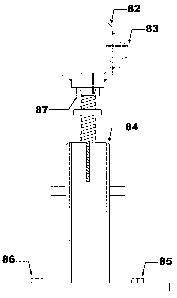
Figure 13 is front view of an anchoring tower with angle bracket accessory
attached.
Figure 14 is a cross sectional view of a an adapted angle bracket accessory
mounted on a frame with track.
Figure 15 is a side view of the adapted angle bracket accessory mounted on a
frame with track.
Figure 16 is a detailed view of the position locking mechanism of the adapted
angle bracket accessory.
Figure 17 is a side view of an anchoring tower with an articulating extension
accessory attached.
Figure 18 is a side view of an anchoring tower mounted on an existing repair
platform.
Figure 19 is a side view of an apparatus providing lift and mobility to an
anchoring tower.
DETAILED DESCRIPTION OF THE PREFERRED EMBODIMENT
In order to better understand the embodiment of the present invention, the
anchoring tower
3

CA 02568194 2006-11-20
component of the anchoring platform will be described with reference to
FIGURES 1 through 4. An
anchoring tower is provided as in FIGURE 1 with an elevating bolt 1 engaged by
means of thread with the
body of the tower and providing an attachment point for mounting accessories.
A chain pull attachment 3 is
provided and allowed to freely move along the thread of said elevating bolt I
while additionally facilitating
anchoring as required. Vice action tightening of the elevating bolt 1 to the
body of the tower is provided by
tightening bolts such as bolt 11. Anchoring tower lifting facility is provided
by lift points such as lift wing
9. The body of the anchoring tower has base 7 and additional accessory
mounting point 5. An anchoring
tower is provided as in FIGURE 2 wherein a frontal view of the body of the
tower 13 is shown further
detailing the configuration of the lift wing 15.
An anchoring tower 21 is provided as in FIGURE 3 detailing the mounting of an
articulation
accessory 27 by means of bolt 23 through accessory mounting point 17. A
section of an extension arm 25 is
shown attached to said articulating accessory 27. Said articulation accessory
27 provides free movement
about axis 19 as well as a range of angular elevation of extension arm 25
allowing the operator to set the
attitude of an extension arm before commencing the work. Additionally, said
articulation accessory 27
provides facility for chain attachment hence anchoring and attachment means.
Further, said articulation
accessory 27 permits attachment of a hydraulic cylinder, similar in form to
said extension arm 25, thereby
providing push and pull facility at the work end of said cylinder.
An anchoring tower 33 is provided as in FIGURE 4 with mounting arms such as 35
and 41
attached by bolt means 43 to anchor points in medium 39. The anchoring tower
33 is further equipped with
pin receptacle 37 to facilitate engagement with mounting arms 35 and 41. A nut
29 is shown which is used
to engage said tightening bolt 11 of FIGURE 1. A handle 31 is shown to engage
said elevating bolt 1 of
FIGURE 1 in order to facilitate fine adjustment of said elevating bolt 1.
Attachment accessories designed to engage the anchoring tower of the present
invention will be
described with reference to FIGURES 5 through 12. A rivet reinforcement washer
45 and a rivet mounting
accessory 46 are provided as in FIGURE 5 wherein said rivet mounting accessory
46 may be used as a
standalone accessory or in combination with said washer 45, to be mounted such
that the inner diameter
engages the outer diameter of the work end of said rivet mounting accessory
46, in order to provide
additional stress support as required by the work. A rivet mounting accessory
is further illustrated in
4

CA 02568194 2006-11-20
FIGURE 6 wherein the body of the accessory 49 is equipped with a tower
attachment point 51 and
threaded pin 47 to engage a rivet at the site of the work. An angle bracket
accessory is provided as in
FIGURE 7 wherein the body of the angle bracket 57 is configured to have
tapered edges enhancing weld
facility at the site of the work and is equipped with tower engagement points
53 and 55 additionally
providing further accessory mounting points. A clamp accessory is provided as
in FIGURE 8 wherein the
body of the accessory 59 is equipped with tower mounting point 63 and
tightening bolt 61. A twist locking
accessory is provided as in FIGURE 9 wherein the bolt 67 is designed to engage
said anchoring tower and
the locking device 65 provides automobile specific mounting. A standard clamp
is provided as in FIGURE
with tightening facility 71 and arms such as 69 providing ease of engagement
with said anchoring tower.
10 A load distributing disc is provided as in FIGURE 11 wherein the body of
the disc 75 is configured with
tapered edges for ease of weld to the work site and a tower engagement point
77. A top view of the load
distributing disc is provided in FIGURE 12 further illustrating the
configuration of the body of the disc 79
and the tower engagement point 81.
An application of the anchoring tower will be described with reference to
FIGURE 13. An
anchoring tower with attached angle bracket accessory is provided as in FIGURE
13. The anchoring tower
84 is shown with angle bracket accessory 82 engaged with the elevating bolt
engagement end 87. Said
engagement end 87 is provided such that it forms the receptacle, or female, of
the engagement point. Said
angle bracket accessory further equipped with mounting accessory 83 as before
in order to be able to
engage additional accessories as required by the work. The anchoring tower 84
is equipped with mounting
bolts such as 85 and 86 illustrating yet another mounting facility of said
anchoring tower.
A embodiment of the angle bracket accessory adapted to engage a frame with a
track will be
described with reference to FIGURES 14 through 16. A frame with track 93 is
shown in FIGURE 14 with
attached angle bracket equipped with mounting points 89 and 91 permitting
mounting to an anchoring
tower and further accessories as necessary. This configuration allows movement
and position locking of
said adapted angle bracket along the axis of the track as required by the
work.
Another view of the adapted angle bracket accessory for use with a frame with
track is provided in
FIGURE 15. The body of the adapted angle bracket 99 may be moved along the
axis of the frame with
track 97 as required by the work and then locked into position by means of
locking mechanism 101. Said
5

CA 02568194 2006-11-20
angle bracket 99 is provided with accessory mounting points 95 and 103.
A detailed illustration of the locking mechanism of the adapted angle bracket
accessory is
provided in FIGURE 16. A locking face 105 provides user adjustment, and
thereby locking of said
accessory into position, of a threaded bolt 107 engaged by a washer 109 and
nut 111. Said locking face 105
is provided such that its weight distribution, defined by its geometry, will
fall into locked position if not
actively unlocked by the operator when used such that the corresponding face
of said angle bracket
accessory is normal to the ground thereby preventing movement when such
movement is undesirable.
An extension arm accessory attached to an anchoring tower will be described
with reference to
FIGURE 17. An anchoring tower 113 is provided as in FIGURE 17 with attached
articulation accessory
129 as before. Said articulation accessory 129 is further attached to an
extension arm accessory 127
designed to be movable through a range of elevation and positional angles as
required by the work. Said
extension arm 127 provides telescopic extension then length locking by sliding
pin 117 through length
selection holes such as 115. The inner cylinder 125 of said extension arm 127
is further equipped with
engagement means 119 for fine length adjustment by means of threaded
adjustment bolt 121. Said
adjustment bolt 121 is provided with accessory engagement thread 123 in order
to be able engage all
accessories designed to engage said anchoring tower above.
An anchoring tower mounted on a commonly available repair platform will be
described with
reference to FIGURE 18. An anchoring tower 131 is provided as in FIGURE 18
mounted to repair
platform 133 by means of clamping action with tower base 141 tightened at
shown location by bolts 137
and 139 thereby allowing the operator to utilize all facilities of the present
invention described above while
engaging an existing platform. An existing mounting bracket 135 is shown
attached to said repair platform
133 to illustrate the common use of said platform.
The lifting and mobility of an anchoring tower will be described with
reference to FIGURE 19. A
lifting apparatus with wheels 143 is provided as in FIGURE 19 so designed to
engage the lift wing 145 on
either side of the anchoring tower 147. Such a lifting apparatus with wheels
143 assists the operator to
safely and easily move said anchoring tower 147 to the desired position within
the work area.
6

Representative Drawing
A single figure which represents the drawing illustrating the invention.
Administrative Status

2024-08-01:As part of the Next Generation Patents (NGP) transition, the Canadian Patents Database (CPD) now contains a more detailed Event History, which replicates the Event Log of our new back-office solution.

Please note that "Inactive:" events refers to events no longer in use in our new back-office solution.

For a clearer understanding of the status of the application/patent presented on this page, the site Disclaimer , as well as the definitions for Patent , Event History , Maintenance Fee  and Payment History  should be consulted.

Event History

Description Date
Inactive: Dead - No reply to s.30(2) Rules requisition 2014-07-04
Application Not Reinstated by Deadline 2014-07-04
Deemed Abandoned - Failure to Respond to Maintenance Fee Notice 2013-11-20
Inactive: Abandoned - No reply to s.30(2) Rules requisition 2013-07-04
Inactive: S.30(2) Rules - Examiner requisition 2013-01-04
Maintenance Request Received 2012-11-19
Letter Sent 2011-11-24
All Requirements for Examination Determined Compliant 2011-11-18
Request for Examination Requirements Determined Compliant 2011-11-18
Request for Examination Received 2011-11-18
Application Published (Open to Public Inspection) 2008-05-20
Inactive: Cover page published 2008-05-19
Inactive: First IPC assigned 2007-02-05
Inactive: IPC assigned 2007-02-05
Inactive: Office letter 2006-12-27
Application Received - Regular National 2006-12-20
Inactive: Filing certificate - No RFE (English) 2006-12-20
Small Entity Declaration Determined Compliant 2006-11-20

Abandonment History

Abandonment Date Reason Reinstatement Date
2013-11-20

Maintenance Fee

The last payment was received on 2012-11-19

Note : If the full payment has not been received on or before the date indicated, a further fee may be required which may be one of the following

  • the reinstatement fee;
  • the late payment fee; or
  • additional fee to reverse deemed expiry.

Patent fees are adjusted on the 1st of January every year. The amounts above are the current amounts if received by December 31 of the current year.
Please refer to the CIPO Patent Fees web page to see all current fee amounts.

Fee History

Fee Type Anniversary Year Due Date Paid Date
Application fee - small 2006-11-20
MF (application, 2nd anniv.) - small 02 2008-11-20 2008-10-21
MF (application, 3rd anniv.) - small 03 2009-11-20 2009-11-20
MF (application, 4th anniv.) - small 04 2010-11-22 2010-11-16
MF (application, 5th anniv.) - small 05 2011-11-21 2011-11-18
Request for examination - small 2011-11-18
MF (application, 6th anniv.) - small 06 2012-11-20 2012-11-19
Owners on Record

Note: Records showing the ownership history in alphabetical order.

Current Owners on Record
GUY N. CHARTIER
Past Owners on Record
None
Past Owners that do not appear in the "Owners on Record" listing will appear in other documentation within the application.
Documents

To view selected files, please enter reCAPTCHA code :


To view images, click a link in the Document Description column (Temporarily unavailable). To download the documents, select one or more checkboxes in the first column and then click the "Download Selected in PDF format (Zip Archive)" or the "Download Selected as Single PDF" button.

List of published and non-published patent-specific documents on the CPD .

If you have any difficulty accessing content, you can call the Client Service Centre at 1-866-997-1936 or send them an e-mail at CIPO Client Service Centre.

({010=All Documents, 020=As Filed, 030=As Open to Public Inspection, 040=At Issuance, 050=Examination, 060=Incoming Correspondence, 070=Miscellaneous, 080=Outgoing Correspondence, 090=Payment})


Document
Description 
Date
(yyyy-mm-dd) 
Number of pages   Size of Image (KB) 
Abstract 2006-11-19 1 13
Description 2006-11-19 6 231
Claims 2006-11-19 3 98
Drawings 2006-11-19 9 98
Representative drawing 2008-04-23 1 4
Filing Certificate (English) 2006-12-19 1 158
Notice: Maintenance Fee Reminder 2008-08-20 1 121
Notice: Maintenance Fee Reminder 2009-08-23 1 128
Notice: Maintenance Fee Reminder 2010-08-22 1 124
Reminder - Request for Examination 2011-07-20 1 118
Notice: Maintenance Fee Reminder 2011-08-22 1 125
Acknowledgement of Request for Examination 2011-11-23 1 176
Notice: Maintenance Fee Reminder 2012-08-20 1 120
Notice: Maintenance Fee Reminder 2013-08-20 1 120
Courtesy - Abandonment Letter (R30(2)) 2013-08-28 1 165
Courtesy - Abandonment Letter (Maintenance Fee) 2014-01-14 1 172
Second Notice: Maintenance Fee Reminder 2014-05-20 1 118
Notice: Maintenance Fee Reminder 2014-08-20 1 128
Correspondence 2006-12-19 1 13
Fees 2008-10-20 1 27
Fees 2009-11-19 1 25
Fees 2010-11-15 1 46
Fees 2011-11-17 1 56
Fees 2012-11-18 1 22