Note: Descriptions are shown in the official language in which they were submitted.
CA 02568197 2006-12-08
BALANCED FLOW' VACUUM CLEANER
TECHNICAL FIELD
The present invention relates to methods and apparatuses for transporting
a flow of air and particulates through a vacuum cleaner.
S BACKGROUND OF THE INVENTION
Conventional upright vacuum cleaners are commonly used in both
residential and commercial settings to remove dust, debris and other
particulates from
floor surfaces. such as carpeting, wood flooring, and linoleum. A n~pical
conventional
upright vacuum cleaner includes a wheel-mounted head which includes an intake
nozzle
positioned close to the floor, a handle that extends upwardly from the head so
the user
can move the vacuum cleaner along the floor while remaining in a standing or
walking
position, and a blower or fan. The blower takes in a flow of air and debris
through the
intake nozzle and directs the flow into a filter bag or receptacle which traps
the debris
while allowing the air to pass out of the vacuum cleaner.
One drawback with some conventional upright vacuum cleaners is that
the flow path along which the flow of air and particulates travels may not be
uniform
and/or may contain flow disruptions or obstructions. Accordingly, the flow may
accelerate and decelerate as it moves from the intake nozzle to the filter
bag, As the
flow decelerates, the particulates may precipitate from the flow and reduce
the cleaning
ZO effectiveness of the vacuum cleaner and lead to blocking of the flow path.
In addition,
the flow disruptions and obstructions can reduce the overall energy of the
flow and
therefore reduce the capacity of a flow to keep the particulates entrained
until the flow
reaches the filter bag.
Another drawback with some conventional upright vacuum cleaners is
that the blowers and flow path can be noisy. For example, one conventional
type of
blower includes rotating fan blades that take in axial flow arriving from the
intake
nozzle and direct the flow into a radially extending tube. As each fan blade
passes the
CA 02568197 2006-12-08
7
entrance opening of the tube, it generates noise which can be annoying to the
user and
to others who may be in the vicinity of the vacuum cleaner while it is in use.
Still another drawback with some conventional upright vacuum cleaners
is that the filter bag may be ineffcient. For example, some filter bags are
constructed
by folding over one end of an open tube of porous filter material to close the
one end..
and leaving an opening in the other end to receive the flow of air and
particulates.
Folding the end of the bag can pinch the end of the bag and reduce the flow
area of the
bag, potentially accelerating the flow through the bag. As the flow
accelerates through
the bag, the particulates entrained in the flow also accelerate and may strike
the walls of
the bag with increased velocity, potentially weakening or breaking the bag and
causing
the particulates to leak from the bag.
SUMMARY OF THE INVENTION
The invention relates to methods and apparatuses for transporting a flow
of air and particulates through a vacuum cleaner. In one embodiment, the
apparatus
includes an intake body having an intake opening configured to be positioned
proximate
to a floor surface for receiving the flow of air and particulates. The vacuum
cleaner can
further include a filter housing configured to receive a filter for separating
the
particulates from the flow of air, and at least one conduit coupled between
the intake
body and the filter housing. An airflow propulsion device is coupled between
the intake
opening and the conduit to draw the flow of air and particulates through the
intake
opening and toward the filter housing. The intake opening, the propulsion
device, and
the conduit define a flow path for the flow of air and particulates and in one
embodiment, the flow path has an approximately constant flow area from the
intake
opening to the propulsion device.
In another embodiment, a radius of curvature of the flow path from the
intake opening through the propulsion device has a radius of a curvature not
less than
approximately 0.29 inches to provide smooth flow along the flow path. In still
another
embodiment, the flow path is divided between two conduits, each extending from
the
CA 02568197 2006-12-08
J
intake body toward the filter housing. In one aspect of this embodiment, the
combined
flow area through the two conduits is less thm the flow area through the
intake opening.
BRIEF DESCRIPTION OF THE DRAWINGS
Figure 1 is a front isometric view of a vacuum cleaner having an intake
body. an airflow propulsion device. a filter and a filter housing in
accordance with an
embodiment of the invention.
Figure 2 is an exploded isometric view of an embodiment of the intake
body and the airflow propulsion device shown in Figure 1.
Figure 3 is an exploded isometric view of the airflow- propulsion device
shown in Figure 2.
Figure 4 is a front elevation view of a portion of the airflow propulsion
device shown in Figure 3.
Figure 5 is a cross-sectional side elevation view of the airflow propulsion
device shown in Figure 3.
Figure 6 is an exploded isometric view of an embodiment of the filter
housing, filter and manifold shown in Figure 1.
Figure 7 is a cross-sectional front elevation view of the filter housing and
filter shown in Figure 1.
Figure 8 is an exploded top isometric view of a manifold in accordance
with another embodiment of the invention.
DETAILED DESCRIPTION OF THE INVENTION
The present invention is directed toward methods and apparatuses for
moving a flow of air and particulates into a vacuum cleaner and separating the
particulates from the air. The apparatus can include an intake passage and an
airflow
propulsion device having an approximately constant flow area to reduce
pressure losses
to the flow. Many specific details of certain embodiments of the invention are
set forth
in the following description and in Figures 1-8 to provide a thorough
understanding of
such embodiments. One skilled in the art. however, will understand that the
present
' CA 02568197 2006-12-08
4
invention may have additional embodiments and that they may be practiced
without
several of the details described in the following description.
Figure 1 is an isometric view of a vacuum cleaner 10 in accordance with
an embodiment of the invention positioned to remove particulates from a floor
surface
20. The vacuum cleaner 10 can include a head or intake body 100 having an
intake
nozzle including an intake aperture 111 for receiving a flow of air and
particulates from
the floor surface 20. An airflow propulsion device 200 draws the flow of air
and
particulates through the intake opening 11 l and directs the flow through two
conduits .
30. The conduits 30 conduct the flow to a manifold 50 that directs the flow
into a filter
element 80. The air passes through porous walls of the filter element 80 and
through a
porous filter housing 70, leaving the particulates in the filter element 80.
The vacuum
cleaner 10 further includes an upwardly extending handle 45 and wheels 90
(shown as
forward wheels 90a and rear wheels 90b) for controlling and moving the vacuum
cleaner over the floor surface 20.
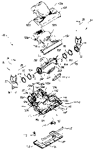
Figure 2 is an exploded isometric view of an embodiment of the intake
body 100 shown in Figure 1. The intake body 100 includes a baseplate I10 and
an
inner cover 150 that are joined together around the airflow propulsion device
200. An
outer cover 130 attaches to the inner cover 150 from above to shroud and
protect the
inner cover 1 SO and the airflow propulsion device 200. A skid plate 116 is
attached to
the lower surface of the baseplate 110 to protect the baseplate 110 from
abrasive contact
with the floor surface 20 (Figure 1 ). Bumpers 115 are attached to the outer
corners of
the baseplate 110 to cushion inadvertent collisions between the intake body
100 and the
walls around which the vacuum cleaner 10 (Figure 1 ) is typically operated.
As shown in Figure 2, the forward wheels 90a and the rear wheels 90b
are positioned to at least partially elevate the baseplate 110 above the floor
surface 20
(Figure 1 ). In one aspect of this embodiment, the rear wheels 90b can have a
larger
diameter than the forward wheels 90a. For example, the rear wheels 90b can
have a
diameter of between four inches and seven inches, and in one embodiment, a
diameter
of five inches. In a further aspect of this embodiment, the rear wheels 90b
can extend
rearwardly beyond the rear edge of the intake body 100. An advantage of this
CA 02568197 2006-12-08
J
arrangement is that it can allow the vacuum cleaner IO to be mare easily moved
over
stepped surfaces, such as staircases. For example. to move the vacuum cleaner
10 from
a lower step to an upper step. a user can roll the vacuum cleaner backwards
over the
lower step until the rear wheels 90b engage the riser of the step. The user
can then pull
the vacuum cleaner 10 upwardly along the riser while the rear wheels 90b roll
along the
riser. Accordingly, the user can move the vacuum cleaner 10 between steps
without
scraping the intake body 100 against the steps. A further advantage is that
the large rear
wheels 90b can make it easier to move the vacuum cleaner 10 from one cleaning
site to
the next when the vacuum cleaner is tipped backward to rest on the rear wheels
alone.
In yet a further aspect of this embodiment, the rear wheels 90b extend
rearwardly of the intake body 100 by a distance at least as great as the
thickness of a
power cord 43 that couples the intake body 100 to the handle 45 (Figure 1 ).
Accordingly, the power cord 43 will not be pinched between the intake body 100
and
the riser when the vacuum cleaner 10 is moved between steps. In an alternate
embodiment. for example, where users move the vacuum cleaner 10 in a forward
direction between steps, the forward wheels 90a can have an increased diameter
and can
extend beyond the forward edge of the intake body 100.
The outer cover 130 can include intake vents 125a for ingesting cooling
air to cool the airflow propulsion device 200. The baseplate 110 can include
exhaust
vents 125b for exhausting the cooling air. Accordingly, cooling air can be
drawn into
the intake body 100 through the intake vents 125a (for example, with a cooling
fan
coupled to the airflow propulsion device 100), past the propulsion device 200
and out
through the exhaust vents 125b. In one aspect of this embodiment, the exhaust
vents
125b are positioned adjacent the rear wheels 90b. Accordingly, the cooling air
can
diffuse over the surfaces of the rear wheels 90b as it leaves the intake body
100, which
can reduce the velocity of the cooling air and reduce the likelihood that the
cooling air
will stir up particulates on the floor surface 20.
The intake aperture 111 has an elongated rectangular shape and extends
across the forward portion of the baseplate 110. A plurality of ribs 119
extend across
the narrow dimension of the intake aperture 111 to structurally reinforce a
leading edge
CA 02568197 2006-12-08
6
121 of the baseplate 110. The skid plate 116 can also include ribs 120 that
are aligned
with the ribs 119. Accordingly, the flow of air and particulates can be drawn
up
through the skid plate 116 and into the intake aperture 111. In one
embodiment, the
intake aperture 111 can have a width of approximately 16 inches and in other
S embodiments. the intake aperture can have a width of approximately 20
inches. In still
further embodiments, the intake aperture 111 can have other suitable
dimensions
depending on the particular uses to which the vacuum cleaner 10 is put.
An agitation device. such as a roller brush 140, is positioned just above
the intake aperture 111 to aid in moving dust. debris, and other particulates
from the
floor surface 20 and into the intake aperture 111. Accordingly, the roller
brush 140 can
include an arrangement of bristles 143 that sweep the particulates into the
intake
aperture 111. The roller brush 140 can be driven by a brush motor 142 via a
flexible
belt 141 or other mechanism.
In one embodiment, both the intake aperture 111 and the roller brush 140
are symmetric about a symmetry plane 122 (shown in Figure 2 in dashed lines)
that
extends upwardly through the center of the intake body .100 and the vacuum
cleaner 10.
An advantage of this configuration is that the intake body 100 can be more
likely to
entrain particulates uniformly across the width of the intake aperture I 11
and less likely
to leave some of the particulates behind. As will be discussed in greater
detail below,
other features of the vacuum cleaner 10 are also symmetric about the symmetry
plane
122.
The intake body 100 further includes a flow channel 112 positioned
downstream of the intake aperture 11 l and the roller brush 140. The flow
channel 112
includes a lower portion 112a positioned in the baseplate 110 and a
corresponding
upper portion 112b positioned in the inner cover 150. When the inner cover 150
,joins
with the baseplate I10, the upper and lower portions 112b and 112a join to
form a
smooth enclosed channel having a channel entrance 113 proximate to the intake
aperture 11 I and the roller brush 140, and a channel exit 114 downstream of
the channel
entrance 113.
CA 02568197 2006-12-08
7
In one embodiment. the flow channel 112 has an approximately constant
flow area from the channel entrance 113 to the channel exit 114. In one aspect
of this
embodiment, the flow area at the channel entrance 113 is approximately the
same as the
flow area of the intake aperture 111 and the walls of the flow channel 112
transition
smoothly from the channel entrance I 13 to the channel exit 114. Accordingly,
the
speed of the flow through the intake aperture 111 and the flow ehamzel 112 can
remain
approximately constant.
As shown in Figure 2. the channel entrance 113 has a generally
rectangular shape with a width of the entrance 113 being substantially greater
than a
height of the entrance 113. The channel exit i 14 has a generally circular
shape to mate
with an entrance aperture 231 of the airflow propulsion device 200. T'he
channel exit
114 is sealably connected to the airflow propulsion device 200 with a gasket
117 to
prevent flow external to the flow channel 112 from leaking into the airflow
propulsion
device and reducing the efficiency of the device.
Figure 3 is an exploded front isometric view of the airflow propulsion
device 200 shown in Figures 1 and 2. In the embodiment shown in Figure 3. the
airflow
propulsion device 200 includes a fan 210 housed between a forward housing 230
and a
rear housing 260. The fan 210 is rotatably driven about a fan axis 218 by a
motor 250
attached to the rear housing 260.
The forward housing 230 includes the entrance aperture 231 that receives
the flow of air and particulates from the flow channel 112. In one embodiment,
the
flow area of the entrance aperture 231 is approximately equal to the flow area
of the
flow channel 112 so that the flow passes unobstructed and at an approximately
constant
speed into the forward housing 230. The forward housing 230 further includes
two exit
apertures 232 (shown as a left exit aperture 232a and a right exit aperture
232b) that
direct the flow radially outwardly after the flow of air and particulates has
passed
through the fan 210. The exit apertures 232 are defined by two wall portions
239,
shown as a forward wall portion 239a in the forward housing 230 and a rear
wall
portion 239b in the rear housing 260. The forward and rear wall portions 239a,
239b
CA 02568197 2006-12-08
g
together define the exit apertures 232 when the forward housing 230 is joined
to the rear
housing 260.
In one embodiment. the forward housing' 230 includes a plurality of
flexible resilient clasps 233, each having a clasp opening 234 that receives a
corresponding tab 264 projecting outwardly from the rear housing 260. In other
embodiments, other devices can be used to secure the two housings 230, 260.
Housing
gaskets 235 between the forward and rear housings 230, 260 seal the interface
therebetween and prevent the flow from leaking from the housings as the flow
passes
through the fan 210.
The fan 210 includes a central hub 211 and a fan disk 212 extending
radially outwardly from the hub 211. A plurality of spaced-apart vanes 213 are
attached
to the disk 212 and extend radially outwardly from the hub 211. In one
embodiment,
the vanes 213 are concave and bulge outwardly in a clockwise direction.
Accordingly,
when the fan 210 is rotated clockwise as indicated by arrow 253, the fan 210
draws the
flow of air and particulates through the entrance aperture 231, pressurizes or
imparts
momentum to the flow, and directs the flow outwardly through the exit
apertures 232.
Each vane 213 has an inner edge 214 near the hub 211 and an outer edge
2I5 spaced radially outwardly from the inner edge. Adjacent vanes 213 are
spaced
apart from each other to define a channel 2I6 extending radially therebetween.
In one
embodiment, the flow area of each channel 216 remains approximately constant
throughout the length of the channel. For example, in one embodiment, the
width W of
each channel 216 increases in the radial direction, while the height H of each
channel
decreases in the radial direction from an inner height (measured along the
inner edge
214 of each vane 213) to a smaller outer height (measured along the outer edge
215 of
each vane). In a further aspect of this embodiment, the sum of the flow areas
of each
channel 216 is approximately equal to the flow area of the entrance aperture
23I.
Accordingly, the flow area frtim the entrance aperture 231 through the
channels 216
remains approximately constant and is matched to the flow area of the inlet
aperture
111, discussed above with reference to Figure 2.
CA 02568197 2006-12-08
9
The fan 210 is powered by the fan motor 250 to rotate in the clockwise
direction indicated by arrow 253. The fan motor 250 has a flange 255 attached
to the
rear housing 260 with bolts 254. The fan motor 250 further includes a shaft
251 that
extends through a shaft aperture 261 in the rear housing 260 to engage the fan
210. A
motor gasket 252 seals the interface between the rear housing 260 and the fan
motor
250 to prevent the flow. from escaping through the shaft aperture 261. One end
of the
shaft 251 is threaded to receive a nut 2~6 for securing the fan 210 to the
shaft. The
other end of the shaft 251 extends away from the fan motor. so that it can be
gripped
while the nut 254 is tightened or loosened,
Figure 4 is a front elevation view of the rear housing 260 and the fan 210
installed on the shaft 251. As shown in Figure 4, the rear housing 260
includes two
circumferential channels 263, each extending around approximately half the
circumference of the fan 210. In one embodiment, the flow area of each
circumferential
channel 263 increases in the rotation direction 253 of the fan 210.
Accordingly, as each
successive vane 213 propels a portion of the flow into the circumferential
channel 263,
the flow area of the circumferential channel increases to accommodate the
increased
flow. In a further aspect of this embodiment, the combined flow area of the
two
circumferential channels 263 (at the point where the channels empty into the
exit
apertures 232) is less than the total flow area through the channels 216.
Accordingly,
the flow will tend to accelerate through the circumferential channels 263. As
will be
discussed in greater detail below with reference to Figure 2, accelerating the
flow may
be advantageous for propelling the flow through the exit apertures 232 and
through the
conduits 30 (Figure 2).
In the embodiment shown in Figure 4, the exit apertures 232 are
positioned 180° apart from each other. In one aspect of this
embodiment, the number of
vanes 213 is selected to be an odd number, for example, nine. Accordingly,
when the
outer edge 215 of the rightmost vane 213b is approximately aligned with the
center of
the right exit aperture 232b, the outer edge 215 of the leftmost vane 213a
(closest to the
left exit aperture 232a) is offset from the center of the left exit aperture.
As a result, the
peak noise created by the rightmost vane 213b as it passes the right exit
aperture 232b
CA 02568197 2006-12-08
does not occur simultaneously with the peak noise created by the leftmost vane
213a as
the leftmost vane passes the left exit aperture 232a. Accordingl~~. the
average of the
noise generated at both exit apertures 333 can remain approximately constant
as the fan
210 rotates. which may be more desirable to those within earshot of the fan.
5 As discussed above. the number of vanes 213 can be selected to be an
odd number when the exit apertures 232 are spaced 180° apart. In
another embodiment.
the exit apertures 232 can be positioned less than 180° apart and the
number of vanes
213 can be selected to be an even number, so long as the vanes are arranged
such that
when the rightmost vane 213b is aligned with the right exit aperture 232b, the
vane
10 closest to the left exit aperture 232a is not aligned with the left exit
aperture. The effect
of this arrangement can be the same as that discussed above (where the number
of vanes
213 is selected to be an odd number), namely, to smooth out the distribution
of noise
generated at the exit apertures 232.
Figure 5 is a cross-sectional side elevation view of the airflow propulsion
device 200 shown in Figure 2 taken substantially along line 5-5 of Figure 2.
As shown
in Figure 5. each vane 213 includes a projection 217 extending axially away
from the
fan motor 250 adjacent the inner edge 214 of the vane. In the embodiment shown
in
Figure 5, the projection 217 can be rounded, and in other embodiments, the
projection
217 can have other non-xounded shapes. In any case, the forward housing 230
includes
a shroud portion 236 that receives the projections 217 as the fan 210 rotates
relative to
the forward housing. An inner surface 237 of the shroud portion 236 is
positioned close
to the projections 217 to reduce the amount of pressurized flow that might
leak past the
vanes 213 from the exit apertures 232. For example, in one embodiment, the
inner
surface 237 can be spaced apart from the projection 217 by a distance in the
range of
approximately O.I inches to 0.2 inches, and preferably about 0.1 inches. An
outer
surface 238 of the shroud portion 236 can be rounded and shaped to guide the
flow
entering the entrance aperture 231 toward the inner edges 214 of the vanes
213. An
advantage of this feature is that it can improve the characteristics of the
flow entering
the fan 210 and accordingly increase the efficiency of the fan. Another
advantage is
CA 02568197 2006-12-08
that the flow may be less turbulent and/or less likely to be turbulent as it
enters the fan
210. and can accordingly reduce the noise produced by the fan 210.
In one embodiment. the fan 210 is sized to rotate at a relative slow rate
while producing a relatively high flow rate. For example, the fan '_' 10 can
rotate at a
rate of 7,700 rpm to move the flow at a peak rate of 132 cubic feet per minute
(cfm).
As the flow rate decreases. the rotation rate increases. For example, if the
intake
aperture 1 I 1 (Figure 2) is obstructed. the same fan 210 rotates at about
8,000 rpm with a
flow rate of about 107 cfm and rotates at about 10,000 rpm with a flow rate of
about 26
cfm.
In other embodiments. the fan 210 can be selected to have different flow
rates at selected rotation speeds. For example. the fan 210 can be sized and
shaped to
rotate at rates of between about 6,500 rpm and about 9.000 rpm and can be
sized and
shaped to move the flow at a peak rate of between about 110 cfm and about 150
cfm. In
any case, by rotating the fan 210 at relatively slow rates while maintaining a
high flow
I S rate of air through the airflow propulsion device 200, the noise generated
by the vacuum
cleaner 10 can be reduced while maintaining a relatively high level of
performance.
In a further aspect of this embodiment, the performance of the airflow
propulsion device 200 (as measured by flow rate at a selected rotation speed)
can be at
least as high when the airflow propulsion device 200 is uninstalled as when
the airflow
propulsion device is installed in the vacuum cleaner 10 (Figure 1 ). This
effect can be
obtained by smoothly contouring the walls of the intake aperture 111 (Figure
2) and the
flow channel 112 (Figure 2). In one embodiment, the intake aperture 111 and
the flow
channel I 12 are so effective at guiding the flow into the airflow propulsion
device 200
that the performance of the device is higher when it is installed in the
vacuum cleaner
10 than when it is uninstalled.
Returning now to Figure 2. the flow exits the airflow propulsion device
200 through the exit apertures 232 in the form of two streams, each of which
enters one
of the conduits 30. In other embodiments, the airflow propulsion device can
include
more than two apertures 232, coupled to a corresponding number of conduits 30.
An
advantage of having a plurality of conduits 30 is that if one conduit 30
becomes
CA 02568197 2006-12-08
12
occluded. for example. with particles or other matter ingested through the
intake
aperture 111, the remaining conduits) 30 can continue to transport the flow
from the
airflow propulsion device. Furthermore. if one of the two conduits 30 becomes
occluded, the tone produced by the vacuum cleaner 10 (Figure 1) can change
more
dramatically than would the tone of a single conduit vacuum cleaner having the
single
conduit partially occluded. Accordingly, the vacuum cleaner 10 can provide a
more
noticeable signal to the user that the flow path is obstructed or partially
obstructed.
Each conduit 30 can include an elbow section 31 coupled at one end to
the exit aperture 232 and coupled at the other end to an upwardly extending
straight
section 36. As was described above with reference to Figure 4, the combined
flow area
of the two exit apertures 232 is less than the flow area through the intake
opening 11 I .
Accordingly, the flow can accelerate and gain sufficient speed to overcome
gravitational forces while travelling upwardly from the elbow sections 31
through the
straight sections 36. In one aspect of this embodiment, the reduced flow area
tail
remain approximately constant from the exit apertures 232 to the manifold 50
(Figure 1 ).
In one embodiment, the radius of curvature of the flow path through the
elbow section 31 is not less than about 0.29 inches. In a further aspect of
this
embodiment, the radius of curvature of the flow path is lower in the elbow
section than
anywhere else between the airflow propulsion device 200 and the filter element
80
(Figure 1 ). In still a further aspect of this embodiment, the minimum radius
of
curvature along the entire flow path, including that portion of the flow path
passing
through the airflow propulsion device 200, is not less than 0.29 inches.
Accordingly,
the flow is less likely to become highly turbulent than in vacuum cleaners
having more
sharply curved flow paths, and may therefore be more likely to keep the
particulates
entrained in the flow.
Each elbow section 31 is sealed to the corresponding exit aperture 232
with an elbow seal 95. In one embodiment, the elbow sections 31 can rotate
relative to
the airflow propulsion device 200 while remaining sealed to the corresponding
exit
aperture 232. Accordingly, users can rotate the conduits 30 and the handle 45
CA 02568197 2006-12-08
13
(Figure 1 ) to a comfortable operating position. In one aspect of this
embodiment. at
least one of the elbow sections 31 can include a downwardly extending tab 34.
When
the elbow section 31 is oriented generally vertically (as shown in Figure 2).
the tab 34
engages a tab stop 35 to lock the elbow section 31 in the vertical
orientation. In one
embodiment, the tab stop 35 can be formed from sheet metal, bent to form a
slot for
receiving the tab 34. The tab stop 3~ can extend rearwardly from the baseplate
110 so
that when the user wishes to pivot the elbow sections 31 relative to the
intake body 100,
the user can depress the tab stop 35 dowmwardly (for example, with the user's
foot) to
release the tab 34 and pivot the elbow sections 31.
In one embodiment, each elbow seal 9~ can include two rings 9l. shown
as an inner ring 91 a attached to the airflow propulsion device 200 and an
outer ring 91 b
attached to the elbow section 31. The rings 91 can include a compressible
material,
such as felt, and each inner ring 91 a can have a surface 92 facing a
corresponding
surface 92 of the adjacent outer ring 91 b. The surfaces 92 can be coated with
Mylar or
another non-stick material that allows relative rotational motion between the
elbow
sections 31 and the airflow propulsion device 200 while maintaining the seal
therebetween. In a further aspect of this embodiment, the non-stick material
is seamless
to reduce the likelihood for leaks between the rings 91. In another
embodiment, the
elbow seal 95 can include a single ring 91 attached to at most one of the
airflow
propulsion device 200 or the elbow section 31. In a further aspect of this
embodiment.
at least one surface of the ring 91 can be coated with the non-stick material
to allow the
ring to more easily rotate.
Each elbow section 31 can include a male flange 32 that fits within a
corresponding female flange 240 of the airflow propulsion device 200, with the
seal 95
positioned between the flanges 32, 240. Retaining cup portions 123, shown as a
lower
retaining cup portion 123a in the base plate 110 and an upper retaining cup
portion 123b
in the inner cover 150, receive the flanges 32, 240. The cup portions 123 have
spaced
apart walls 124, shown as an inner wall 124a that engages the female flange
240 and an
outer wall 124b that engages the male flange 32. The walls 124a, 124b are
close
enough to each other that the flanges 32, 240 are snugly and sealably engaged
with each
CA 02568197 2006-12-08
14
other, while still permitting relative rotational motion of the male flanges
32 relative to
the female flanges 240.
Figure 6 is a front exploded isometric view of the conduits 30. the filter
housing 70. the manifold 50 and the propulsion device 200 shown in Figure 1.
Each of
these components is arranged symmetrically about the symmetry plane I22.
Accordingly, in one embodiment, the entire flow path from the intake opening
111
(Figure 2) through the manifold 50 is symmetric with respect to the symmetry
plane
122. Furthermore, each of the components along the flow path can have a smooth
surface facing the flow path to reduce the likelihood for decreasing the
momentum of
the flow.
As shown in Figure 6, the conduits 30 include the elbow sections 31
discussed above with reference to Figure 2, coupled to the straight sections
36 which
extend upwardly from the elbow sections 31. In one embodiment, each straight
section
36 is connected to the corresponding elbow section 31 with a threaded coupling
38.
Accordingly, the upper portions of the elbow sections 31 can include tapered
external
threads 37 and slots 40. Each straight section 36 is inserted into the upper
portion of the
corresponding elbow section 31 until an O-ring 39 toward the lower end of the
straight
section is positioned below the slots 40 to seal against an inner wall of the
elbow
section 31. The coupling 38 is then threaded onto the tapered threads 37 of
the elbow
section 31 so as to draw the upper portions of the elbow section 31 radially
inward and
clamp the elbow section around the straight section 36. The couplings 38 can
be
loosened to separate the straight sections 36 from the elbow sections 31, for
example, to
remove materials that might become caught on either section.
Each straight section 36 extends upwardly on opposite sides of the filter
housing 70 from the corresponding elbow section 31 into the manifold S0.
Accordingly, the straight sections 36 can improve the rigidity and stability
of the
vacuum cleaner I 0 (Figure 1 ) and can protect the housing 70 from incidental
contact
with furniture or other structures during use. In the manifold S0, the flows
from each
straight section 36 are combined and directed into the filter element 80, and
then
through the filter housing 70, as will be discussed in greater detail below.
CA 02568197 2006-12-08
la
The manifold 50 includes a lower portion 51 attached to an upper portion
52. The lower portion 51 includes two inlet ports 53, each sized to receive
flow from a
corresponding one of the straight sections 36. A flow passage 54 extends from
each
inlet port 53 to a common outlet port 59. As shown in Figure 6, each flow
passage 54 is
bounded by an upward facing surface 55 of the lower portion 51. and by a
downward
facing surface 56 of the upper portion 52. The lower portion 51 can include a
spare belt
141 a stored beneath the upward facing surface 55. The spare belt 141 a can be
used to
replace the belt 141 (Figure 2) that drives the roller brush 140 (Figure 2).
In the embodiment shown in Figure 6, the outlet port ~9 has an elliptical
shape elongated along a major axis. and the flow passages 54 couple to the
outlet port
59 at opposite ends of the major axis. In other embodiments, the flow passages
can
couple to different portions of the outlet port 59, as will be discussed in
greater detail
below with reference to Figure 8. In still further embodiments, the outlet
port 59 can
have a non-elliptical shape.
Each flow passage 54 turns through an angle of approximately 180°
between a plane defined by the inlet ports 53 and a plane defined by the
outlet port 59.
Each flow passage 54 also has a gradually increasing flow area such that the
outlet port
59 has a flow area larger than the sum of the flow areas of the two inlet
ports 53.
Accordingly. the flow passing through the flow passages 54 can gradually
decelerate as
it approaches the outlet port 59. As a result, particulates can drop into the
filter element
80 rather than being projected at high velocity into the filter element 80. An
advantage
of this arrangement is that the particulates may be less likely to pierce or
otherwise
damage the filter element 80.
As shown in Figure 6, the outlet port 59 can be surrounded by a lip 58
that extends downwardly toward the filter element 80. In one aspect of this
embodiment, the lip 58 can extend into the filter element to seal the
interface between
the manifold 50 and the filter element 80. As will be discussed in greater
detail below,
the filter element 80 can include a flexible portion that sealably engages the
lip 58 to
reduce the likelihood of leaks at the interface between the manifold 50 and
the filter
element 80.
CA 02568197 2006-12-08
1~
In one embodiment. the filter element 80 includes a generally tubular-
shaped wall 81 having a rounded rectangular or partially ellipsoidal cross-
sectional
shape. The wall 81 can include a porous filter material, such as craft paper
lined with a
fine fiber fabric, or other suitable materials, so long as the porosity of the
material is
sufficient to allow air to pass therethrough while preventing particulates
above a
selected size from passing out of the filter element 80. The wall 81 is
elongated along
an upwardly extending axis 85 and can have opposing portions that curve
outwardly
away from each other. In one embodiment, the wall 81 is attached to a flange
82 that
can include a rigid or partially rigid material, such as cardboard and that
extends
outwardly from the wall 81. The flange 82 has an opening 83 aligned with the
outlet
port 59 of the manifold 50. In one embodiment, the opening 83 is lined with an
elastomeric rim 84 that sealably engages the lip 58 projecting downwardly from
the
outlet port 59 of the manifold 50. In one aspect of this embodiment, the
flange 82 is
formed from two layers of cardboard with an elastomeric layer in between. such
that the
elastomeric layer extends inwardly from the edges of the cardboard in the
region of the
outlet port 59 to form the elastomeric rim 84.
In one embodiment, the lower end of the filter element 80 is sealed by
pinching .opposing sides of the wall 81 together. In another embodiment, the
end of the
filter element 80 is sealed by closing the opposing sides of the wall 81 over
a mandrel
(not shown) such that the cross-sectional shape of the filter element is
generally
constant from the flange 82 to a bottom 86 of the filter element 80. An
advantage of
this arrangement is that the flow passing through the filter element 80 will
be less likely
to accelerate, which may in turn reduce the likelihood that the particles
within the flow
or at the bottom of the filter element 80 will be accelerated to such a
velocity as to
pierce the wall 81 or otherwise damage the filter element 80. In this manner,
lighter-
weight particles may be drawn against the inner surface of the wall 81, and
heavier
particles can fall to the bottom 86 of the filter element 80.
As shown in Figure 6, the filter element 80 is removably lowered into
the filter housing 70 from above. In one embodiment, the filter housing 70 can
include
a tube having a wall 75 elongated along the axis 85. The wall 75 can be formed
from a
CA 02568197 2006-12-08
17
porous material. such as a woven polyester fabric. connected to an upper
support 71 and
a lower support 72. The upper support 71 can have a generally flat upwardly
facing
surface that receives the flange 82 of the filter element 80. The forward
facing surface
of the wall 7~ can include text and/or figures. for example, a company name,
logo. or
advertisement. The forward and rear portions of the wall 75 can curve
outwardly away
from each other to blend with intermediate opposing side walls adjacent the
conduits
30, and to correspond generally to the shape of the filter element 80.
Each of the supports 71, 72 includes an upper portion 73a and a lower
portion 73b fastened together with screws 74. As is best seen in cross-section
in
Figure 7, each upper portion 73a has a flange 78a that extends alongside a
corresponding flange 78b of the lower portion 73b. clamping an edge of the
wall 75 of
the filter housing 70 therebetween. In other embodiments, the supports 71, 72
can
include other arrangements for supporting the housing 70. The lower portion
73b of the
lower support 72 has a closed lower surface 67 that forms the base of the
filter housing
70. The upper portion 73a of the lower support 72 and both the upper and lower
portions of the upper support 71 have open upper surfaces that allow the
filter housing
70 to extend upwardly therethrough, and allow the filter element 80 to drop
downwardly into the filter housing.
Returning to Figure 6, the upper and lower supports 71, 72 each have
conduit apertures 77 sized to receive the straight sections 36. In one
embodiment. the
conduit apertures 77 are surrounded by flexible projections 69 attached to the
lower
portions 73b of each support 71, 72. The projections 69 clamp against the
straight
section 36 to restrict motion of the straight sections 36 relative to the
supports 71, 72.
In a further aspect of this embodiment, the projections 69 of the upper
support 71 have
circumferentiai protrusions 68 that engage a corresponding groove 41 of the
straight
section 36 to prevent the straight section 36 from sliding axially relative to
the upper
support 71.
The upper and lower supports 71, 72 also include handle apertures 76
that receive a shaft 47 of the handle 45. The lowermost aperture 76a has a
ridge 79 that
engages a slot 44 of the handle shaft 47 to prevent the shaft from rotating.
The handle
CA 02568197 2006-12-08
18
45 includes a grip portion 48 which extends upwardly beyond the filter housing
70
where it can be grasped by the user for moving the vacuum cleaner 10 (Figure 1
) and%or
for rotating the filter housing 70 and the conduits 30 relative to the airflow
propulsion
device 200, as was discussed above with reference to Figure 2. The grip
portion 48 can
also include a switch 46 for activating the vacuum cleaner 10. The switch 46
can be
coupled with an electrical cord 49 to a suitable power outlet, and is also
coupled to the
fan motor 250 (Figure 3) and the brush motor 42 (Figure 2) with electrical
leads (not
shovv~~ j.
The upper support 71 includes two gaskets 57 for sealing with the
manifold 50. In one embodiment, the manifold 50 is removably secured to the
upper
support 7l with a pair of clips 60. Accordingly, the manifold 50 can be easily
remo~~ed
to access the filter element 80 and the spare belt or belts 141a. In mother
embodiment,
the manifold 50 can be secured to the upper support 71 with any suitable
releasable
latching mechanism, such as flexible, extendible bands 60a shown in hidden
lines in
Figure 6.
Figure 8 is an exploded isometric view of a manifold 50a in accordance
with another embodiment of the invention. The manifold SOa includes a lower
portion
51 a connected to an upper portion 52a. The lower portion 5I a has an outlet
port 59
with an elliptical shape elongated along a major axis. Flow passages 54a
couple to the
outlet port 59 toward opposite ends of a minor axis that extends generally
perpendicular
to the major axis. The flow passages 54a are bowided by an upward facing
surface 55a
of the lower portion 51a and by a downward facing surface 50a of the upper
portion
52a, in a manner generally similar to that discussed above with reference to
Figure 6.
From the foregoing it will be appreciated that, although specific
embodiments of the invention have been described herein for purposes of
illustration,
various modifications may be made without deviating from the spirit and scope
of the
invention. Accordingly, the invention is not limited except as by the appended
claims.