Note: Descriptions are shown in the official language in which they were submitted.
CA 02568247 2006-12-05
TITLE OF THE INVENTION
CANCELLATION OF PILOT AND UNWANTED
TRAFFIC SIGNALS IN A CDMA SYSTEM
This application is a divisional of Canadian patent
application Serial No. 2,347,207 filed internationally on
January 27, 1999 and entered nationally on April 10, 2001.
BACKGROUND OF THE INVENTION
Field of the Invention
The present invention relates generally to digital
communications. More specifically, the invention relates to a
system and method which cancels the global pilot signal and
unwanted traffic signals from a received code division multiple
access signal thereby removing them as interferers prior to
decoding.
Description of the Prior Art
Advanced communication technology today makes use of a
communication technique in which data is transmitted with a
broadened band by modulating the data to be transmitted with a
pseudo-noise (pn) signal. The technology is known as digital
spread spectrum or code divisional multiple access (CDMA). By
transmitting a signal with a bandwidth much greater than the
signal bandwidth, CDMA can transmit data without being affected
CA 02568247 2006-12-05
-2-
by signal distortion or an interfering frequency in the
transmission path.
Shown in Figure 1 is a simplified, single channel CDMA
communication system. A data signal with a given bandwidth is
mixed with a spreading code generated by a pn sequence
generator producing a digital spread spectrum signal. The
signal which carries data for a specific channel is known as a
traffic signal. Upon reception, the data is reproduced after
correlation with the same pn sequence used to transmit the
data. Every other signal within the transmission bandwidth
appears as noise to the signal being despread.
For timing synchronization with a receiver, an unmodulated
traffic signal known as a pilot signal is required for every
transmitter. The pilot signal allows respective receivers to
synchronize with a given transmitter, allowing despreading of a
traffic signal at the receiver.
In a typical communication system, a base station
communicates with a plurality of individual subscribers fixed
or mobile. The base station which transmits many signals,
transmits a global pilot signal common to the plurality of
users serviced by that particular base station at a higher
power level. The global pilot is used for the initial
acquisition of an individual user and for the user to obtain
signal-estimates for coherent reception and for the combining
of multipath components during reception. Similarly, in a
CA 02568247 2006-12-05
-3-
reverse direction, each subscriber transmits a unique assigned
pilot for communicating with the base station.
Only by having a matching pn sequence can a signal be
decoded, however, all signals act as noise and interference.
The global pilot and traffic signals are noise to a traffic
signal being despread. If the global pilot and all unwanted
traffic signals could be removed prior to despreading a desired
signal, much of the overall noise would be reduced, decreasing
the bit error rate and in turn, improve the signal-to-noise
ratio (SNR) of the despread signal.
Some attempts have been made to subtract the pilot signal
from the received signal based on the relative strength of the
pilot signal at the receiver. U.S. Patent No. 5,224,122 to
Brackert discloses a spread-spectrum noise canceler which
cancels a portion of spread-spectrum noise signal in the
received signal by generating an estimated signal by spreading
the known signal. Subsequently, the known signal is processed
out of the received spread-spectrum signal by subtracting the
estimated signal from the demodulated form of the received
spread-spectrum signal. Where the estimated signals is
generated based on the amplitude and the phase information of
the known signals received from a base station in a primary
serving cell, and the amplitudes information from the noise of
multipath signal and the noise signal from a secondary serving
cell. WO 98 43362 to Yellin et al. disclosues a CDMA noise
CA 02568247 2011-06-07
- 4 -
canceler by detecting at least one noisy user signal from a
spread-spectrum signal and removing the noise of pilot signal and
its interference effect the particular user signal. However, the
strength value is not an accurate characteristic for calculating
interference due to the plurality of received signals with
different time delays caused by reflections due to terrain.
Multipath propagation makes power level estimates unreliable.
There is a need to improve overall system performance by
removing multiple noise contributors from a signal prior to
decoding.
SUMMARY OF THE INVENTION
The present invention reduces the contributive noise effects
of the global pilot signal and unwanted traffic signals
transmitted in a spread spectrum communication system. The
present invention effectively cancels the global pilot and
unwanted traffic signal (s) from a desired traffic signal at a
receiver prior to decoding. The resulting signal has an increased
signal-to-noise ratio.
An aspect of the present disclosure provides a method for
removing a selected signal from a received signal. The method
comprises receiving code division multiple access (CDMA) signals
including a first signal and a second signal, the first signal
being spread with a first spreading code and the second signal
being spread with a second spreading code; despreading the
received CDMA signals with a complex conjugate of the first
CA 02568247 2011-06-07
-
spreading code to generate a first de-spread signal; despreading
the received CDMA signals with a complex conjugate of the second
spreading code to generate a second de-spread signal; generating
a symbol value based on the second de-spread signal; generating a
5 second signal strength based on the second de-spread signal;
calculating a correlation of the second spreading code and a
complex conjugate of the first spreading code; generating a
cancellation signal component based on the correlation, the
second signal strength, and the symbol value; and subtracting the
cancellation signal component from the first de-spread signal.
Another aspect of the present disclosure provides a method
for removing the pilot signal from a received signal. The method
comprises receiving code division multiple access (CDMA) signals
including a first signal and a pilot signal, the first signal
being spread with a first spreading code and the pilot signal
being spread with a pilot spreading code; despreading the
received CDMA signals with a complex conjugate of the first
spreading code to generate a first de-spread signal; despreading
the received CDMA signals with a complex conjugate of the pilot
spreading code to generate a second de-spread signal; generating
a pilot signal strength based on the second de-spread signal;
calculating a correlation of the pilot spreading code and a
complex conjugate of the first spreading code; generating a pilot
cancellation signal component based on the correlation and the
pilot signal strength; and subtracting the pilot cancellation
signal component from the first de-spread signal.
CA 02568247 2011-06-07
6 -
A further aspect of the present disclosure provides an
apparatus configured to remove a selected signal from a received
signal. The apparatus comprises a receiver for receiving code
division multiple access (CDMA) signals including a first signal
and a second signal, the first signal being spread with a first
spreading code and the second signal being spread with a second
spreading code; a first despreader for despreading the received
CDMA signals with a complex conjugate of the first spreading code
to generate a first de-spread signal; a second despreader for
despreading the received CDMA signals with a complex conjugate of
the second spreading code to generate a second de-spread signal;
a hard decision processor for generating a symbol value based on
the second de-spread signal; a signal strength generation device
for generating a second signal strength based on the second de-
spread signal; a correlator for calculating a correlation of the
second spreading code and a complex conjugate of the first
spreading code; a cancellation signal generation device for
generating a cancellation signal component based on the
correlation, the second signal strength, and the symbol value;
and a subtractor for subtracting the cancellation signal
component from the first de-spread signal.
A yet further aspect of the present disclosure provides an
apparatus for removing the pilot signal from a received signal.
The apparatus comprises a receiver for receiving code division
multiple access (CDMA) signals including a first signal and a
pilot signal, the first signal being spread with a first
CA 02568247 2011-06-07
- 7 -
spreading code and the pilot signal being spread with a pilot
spreading code; a first despreader for despreading the received
CDMA signals with a complex conjugate of the first spreading code
to generate a first de-spread signal; a second despreader for
despreading the received CDMA signals with a complex conjugate of
the pilot spreading code to generate a second de-spread signal; a
pilot signal strength generator for generating a pilot signal
strength based on the second de-spread signal; a correlator for
calculating a correlation of the pilot spreading code and a
complex conjugate of the first spreading code; a cancellation
signal generator for generating a pilot cancellation signal
component based on the correlation and the pilot signal strength;
and a subtractor for subtracting the pilot cancellation signal
component from the first de-spread signal.
Accordingly, it is an object of the present invention to
provide a code division multiple access communication system
receiver which reduces the contributive noise effects from the
pilot and active, unwanted traffic signals.
CA 02568247 2006-12-05
-8-
It is another object of the present invention to improve
the desired traffic signal SNR by eliminating the noise effects
of the global pilot and active traffic signals.
Other objects and advantages of the system and method will
become apparent to those skilled in the art of advanced
telecommunications after reading the detailed description of
the preferred embodiment.
BRIEF DESCRIPTION OF THE DRAWINGS
Figure 1 is a simplified block diagram of a prior art,
CDMA communication system.
Figure 2A is a detailed block diagram of a B-CDM.ATM
communication system.
Figure 2B is a detailed system diagram of a complex number
multiplier.
Figure 3A is a plot of an in-phase bit stream.
Figure 3B is a plot of a quadrature bit stream.
Figure 3C is a plot of a pseudo-noise (pn) bit sequence.
Figure 4 is a block diagram of a global pilot signal
cancellation system according to the present invention.
Figure 5 is a block diagram of an unwanted traffic
signal(s) cancellation system according to the present
invention.
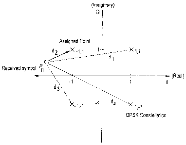
Figure 6 is a diagram of a received symbol po on the QPSK
constellation showing a hard decision.
CA 02568247 2006-12-05
-9-
Figure 7 is a block diagram of a combined pilot and
unwanted traffic signal cancellation system according to the
present invention.
DESCRIPTION OF THE PREFERRED EMBODIMENTS
The preferred embodiments will be described with reference
to the drawing figures where like numerals represent like
elements throughout.
A B-CDMATM communication system 17 as shown in Figure 2
includes a transmitter 19 and a receiver 21, which may reside
in either a base station or a mobile user receiver. The
transmitter 19 includes a signal processor 23 which encodes
voice and nonvoice signals 25 into data at various bit rates.
By way of background, two steps are involved in the
generation of a transmitted signal in a multiple access
environment. First, the input data which can be considered a
bi-phase modulated signal is encoded using forward error-
correcting coding (FEC) 27. One signal is designated the in-
phase channel 133x. The other signal is designated the
quadrature channel Q 33y. Bi-phase modulated I and Q signals
are usually referred to as quadrature phase shift keying
(QPSK).
In the second step, the two bi-phase modulated data or
symbols 33x, 33y are spread with a complex, pseudo-noise (pn)
sequence 351, 35Q using a complex number multiplier 39. The
CA 02568247 2006-12-05
- 10-
operation of a complex number multiplier 39 is shown in Figure
2B and is well understood in the art. The spreading operation
can be represented as:
(x + jy) x (I+ jQ) _ (xI - yQ) + j (xQ + yI) = a+ jb. Equation (1)
A complex number is in the form a+jb, where a and b are
real numbers and j2=-1. Referring back to Figure 2a, the
resulting 137a and Q 37b spread signals are combined 45a, 45b
with other spread signals (channels) having different spreading
codes, multiplied (mixed) with a carrier signal 43, and
transmitted 47. The transmission 47 may contain a plurality of
individual signals.
The receiver 21 includes a demodulator 49a, 49b which
mixes down the transmitted broadband signal 47 with the
transmitting carrier 43 into an intermediate carrier frequency
51a, 51b. A second down conversion reduces the signal to
baseband. The QPSK signal 55a, 55b is then filtered 53 and
mixed 56 with the locally generated complex pn sequence 35I,
35Q which matches the conjugate of the transmitted complex
code. Only the original signals which were spread by the same
code will be despread. All other signals will appear as noise
to the receiver 21. The data 57x, 57y is coupled to a signal
processor 59 where FEC decoding is performed on the
convolutionally encoded data.
As shown in Figures 3A and 3B, a QPSK symbol consists of
CA 02568247 2006-12-05
-11-
one bit each from both the in-phase (I) and quadrature (Q)
signals. The bits may represent a quantized version of an
analog sample or digital data. It can be seen that symbol
duration is is equal to bit duration.
The transmitted symbols are spread by multiplying the QPSK
symbol stream by the complex pn sequence. Both the I and Q pn
sequences are comprised of a bit stream generated at a much
higher frequency, typically 100 to 200 times the symbol rate.
One such pn sequence is shown in Figure 3C. The complex pn
sequence is mixed with the symbol bit stream producing the
digital spread signal (as previously discussed). The
components of the spread signal are known as chips having a
much smaller duration t,.
When the signal is received and demodulated, the baseba.nd
signal is at the chip level. When the I and Q components of
the signal are despread using the conjugate of the pn sequence
used during spreading, the signal returns to the symbol level.
The embodiments of the present invention are shown in
Figures 4, 5 and 7. The global pilot signal cancellation
system 61 embodiment is shown in Figure 4. A received signal r
is expressed as:
r =c cp + J3ct + n Equation (2)
where the received signal r is a complex number and is
CA 02568247 2006-12-05
-12-
comprised of the pilot strength a multiplied with the pilot
code c,, summed with the traffic strength Q multiplied with
the traffic code ct, summed with random noise n. The noise n
includes all received noise and interference including all
other traffic signals. To cancel the global pilot signal from
the received signal r, the system 61 must derive the signal
strength of the pilot code a where:
O C# Q Equation (3)
since the global pilot is transmitted at a higher power level
than a traffic signal.
When the received signal r is summed over time, Equation
(2) becomes:
Ir=ocIcp+f3Zc,+Zn. Equation (4)
Referring to Figure 4, the received baseband signal r is
input 63 into the pilot signal cancellation system 61 and into
a pilot despreader 65 which despreads the pilot signal from the
received signal r. First mixer 67 despreads the received
signal r by multiplying with the complex conjugate cp* 69 of
the pilot pn code used during spreading yielding:
rcp =a Z cpcp + /3> crcp + I ncp. Equation (5)
A complex conjugate is one of a pair of complex numbers with
identical real parts and with imaginary parts differing only in
sign.
The despread pilot signal 71 is coupled to a first sum and
CA 02568247 2006-12-05
- 13-
dump processor 73 where it is summed over time. The first sum
and dump 73 output Osdi is:
Osdt = C L+ c,cp + E ncp Equation (6)
where L is the product of the pilot spreading code cp and the
complex conjugate of the pilot spreading code cp* summed over L
chips.
The sum and dump 73 output Osdl is coupled to a low pass
filter 75. The low pass filter 75 determines the mean value
for each signal component. The mean value for pilot-traffic
cross-correlation is zero and so is the mean value of the noise
n. Therefore, after filtering 75, the second and third terms in
Equation (6) become zero. The low pass filter 75 output Olpf
over time is:
Olb f = a L. Equation (77)
The low pass filter 75 output Olpf is coupled to a
processing means 77 to derive the pilot code strength oc. The
processing means 77 calculates oc by dividing the low pass
filter 79 output Olpf by L. Thus, the processing means 77
output Opm is:
Opm =oc. Equation (8)
The pilot spreading code cp* complex conjugate generator
69 is coupled to a complex conjugate processor 79 yielding the
pilot spreading code cp. The pilot spreading code cp is input
CA 02568247 2006-12-05
-14-
to a second mixer 81 and mixed with the output of a traffic
spreading code ct* complex conjugate generator 83. The
resulting product from the second mixer 81 output is coupled to
a second sum and dump processor 85. The output Osd2 of the
second sum and dump processor 85 is Ecpct* and is combined with
at a third mixer 87. The third mixer 87 output 89 is a Ecpct*.
The received signal r is also despread by traffic
despreader 91. The traffic despreader 91 despreads the
received signal r by mixing the received signal r with the
traffic code ct* complex conjugate generator 83 using a fourth
mixer 93 yielding:
rc* =oc E cpc~ + fl c,cl + Z ncr . Equation (9)
The traffic despreader 91 output 95 is coupled to a third sum
and dump 97. The third sum and dump 97 output Osd3 over time
is:
Osd3 = rct = A+ a c pc* + nc~ Equation (3.0)
where L is the product of the traffic spreading code ct and the
complex conjugate of the traffic spreading code ct* summed over
L chips.
The third sum and dump 97 output Osd3 is coupled to an
adder 99 which subtracts the third mixer 87 output 89. The
adder 99 output Oadd is:
Oadd = QL+ oC I cpcr + E nc, - a E cpcr 1 Equation (11)
CA 02568247 2006-12-05
- 15-
Thus, the pilot canceler 61 output Oadd is equal to the
received signal r minus the pilot signal simplified below:
Oadd = ,QL + I nct . Equation (12)
The invention uses a similar approach to cancel unwanted
traffic signal(s) from a desired traffic signal. While traffic
signals are interference to other traffic signals just as the
global pilot signal is, unwanted traffic signal cancellation
differs from global pilot signal cancellation since a traffic
signal is modulated by the data and is therefore dynamic in
nature. A global pilot signal has a constant phase, whereas a
traffic signal constantly changes phase due to data modulation.
The traffic signal canceler system 101 embodiment is shown
in Figure 5. As above, a received signal r is input 103 to the
system:
r= `Pdcd+Qct+n Equation (13)
where the received signal r is a complex number and is
comprised of the traffic code signal strength 4r multiplied with
the traffic signal data d and the traffic code Cd for the
unwanted traffic signal to be canceled, summed with the desired
traffic code strength Q multiplied with the desired traffic
code ct, summed with noise n. The noise n includes all
received noise and interference including all other traffic
signals and the global pilot signal. To cancel the unwanted
CA 02568247 2006-12-05
-16-
traffic signal(s) from the received signal r, the system 101
must derive the signal strength of the unwanted traffic code 4'
to be subtracted and estimate the data d, where:
`' # d# 8. Equation (14)
When the received signal r is summed over time, Equation
13 can be expressed as:
I r = P d I cd + /3 E C, + I n. Equation (15)
Referring to Figure 5, the received baseband signal r is
input 103 into the desired traffic signal despreader 91 which
despreads the desired traffic signal from the received signal
r. Desired traffic signal mixer 93 mixes the received signal r
with the complex conjugate ct* of the desired traffic pn code
used during spreading. The despread traffic signal is coupled
to a sum and dump processor 97 and summed over time. The sum
and dump 97 output Osd3 is:
O,,d3 = Y-rc, = /3L + 'Y d E cdcl + E ncl . Equation (16)
The traffic signal canceler system 101 shown in Figure 5
includes n unwanted traffic signal cancelers 1151-115,,. An
exemplary embodiment includes 10 (where n=10) unwanted traffic
signal cancelers 1151-1151o
Each unwanted traffic signal canceler 1151-115n comprises:
an unwanted traffic signal despreader 1391-139,, that includes a
first mixer 1171-117,, and an unwanted traffic signal code
generator 1191-119,,; second 1331-133n mixer, first 1211-121,, and
CA 02568247 2006-12-05
-17-
second 1231-123,, sum and dump processors, a hard decision
processor 1251-125,,, a low pass filter 1271-127,,, a processing
means 1291-129xõ third mixer 1311-131,,, a conjugate processor
1351-135,,, an adjustable amplifier 1371-137,,, and a desired
traffic signal code generator 83.
As above, the received signal r is input 103 into each
unwanted traffic canceler 1151-115,,. The unwanted traffic
signal despreader 1391-139,, is coupled to the input 103 where
the received signal r is mixed 1171-117õ with the complex
conjugate cdl*-cd,,* of the traffic pn sequence for each
respective unwanted signal. The despread 1391-139,, traffic
signal is coupled to a first sum and dump processor 1211-121,,
where it is summed over time. The first sum and dump 1211-121õ
Output Osdln is:
OsdIn = rcdõ = PdL+ Q c,cdn + Z ncd,,. Equation (17)
where L is the product of the unwanted traffic signal spreading
code cd,, and cd,,* is the complex conjugate of the unwanted
traffic signal spreading code.
The first sum and dump 1211-121õ output Osdln is coupled to
the hard decision processor 1251-125,,. The hard decision
processor 1251-125õ determines the phase shift tp in the data
due to modulation. The hard decision processor 1251-125õ also
determines the QPSK constellation position d that is closest to
the despread symbol value.
CA 02568247 2006-12-05
-18-
As shown in Figure 6, the hard decision processor 1251-
125,, compares a received symbol po of a signal to the four QPSK
constellation points x1, 1, x-1, 1, x-1, -1, x1, -1. It is necessary
to examine each received symbol po due to corruption during
transmission 47 by noise and distortion, whether muitipath or
radio frequency. The hard decision processor computes the four
distances d1i d2, d3, d4 to each quadrant from the received
symbol po and chooses the shortest distance d2 and assigns that
symbol d location x_1, 1. The hard decision processor also
derotates (rotates back) the original signal coordinate p,, by a
phase amount 0 that is equal to the phase corresponding to the
selected symbol location x-1, 1. The original symbol coordinate
po is discarded.
The hard decision processor 1251-125õ phase output 0 is
coupled to a low pass filter 1271-127,,. Over time, the low
pass filter 1271-127n determines the mean value for each signal
component. The mean value of the traffic-to-traffic cross-
correlation and also the mean value of the noise n are zero.
Therefore, the low pass filter 1271-127n output O1pfn over time
is:
Olpfõ _ `1' L= Equation (18)
The low pass filter 1271-127,, output Olpfn is coupled to the
processing means 1291-129n to derive the unwanted traffic
signal code strength 4r. The processing means 1291-129,,
CA 02568247 2006-12-05
-19-
estimates cp by dividing the filter 1271-127,, output Olpfn by L.
The other hard decision processor 1251-125,, output is data
d. This is the data point d corresponding to the smallest of
the distances dl, d2, d3, or d4 as shown in Figure 6. Third
mixer 1311-131,, mixes the unwanted traffic signal strength 4'
with each date value d.
The unwanted traffic signal spreading code complex
conjugate generator cdl*-cdn* is coupled to the complex
conjugate processor 1351-1350 yielding the unwanted traffic
signal spreading code cdl-cd,, and is input to the second mixer
1331-1330 and mixed with the output of desired traffic signal
spreading code complex conjugate generator ct*. The product is
coupled to the second sum and dump processor 1231-123,,. The
second sum and dump processor 1231-123,, output Osd2n is Ecdnct*
and is coupled to variable amplifier 1371-1370. Variable
amplifier 1371-1370 amplifies the second sum and dump processor
1231-1230 output 0Sd2n in accordance with the third mixer 1311-
131,, output which is the determined gain.
The variable amplifier 1371-1370 output 1411-1410 is
coupled to an adder 143 which subtracts the output from each
variable amplifier 1371-1370 from the output of the desired
traffic signal despreader 105. The output 0 is:
O= PL + 'Pd l CdC, + I nc* - `P d l CdC(. Equation (19)
The adder 143 output 0 (also the unwanted traffic canceler
CA 02568247 2006-12-05
-20-
system 101 output) is equal to the received signal r minus the
unwanted traffic signals simplified below:
O = ,6L + X nct Equation (20)
where the noise n varies depending on the amount of traffic
signals subtracted from the received signal.
Another embodiment 145 canceling the global pilot signal
and unwanted traffic signals is shown in Figure 7. As
previously discussed, the unwanted traffic cancellation system
101 includes the desired traffic signal despreader 91 and a
plurality of unwanted traffic signal cancelers 1151-115,,. The
traffic cancellation system is coupled in parallel with the
pilot cancellation system 61 previously described, but without
a desired traffic signal despreader. A common input 147 is
coupled to both systems 101, 61 with a common adder 149 which
is coupled to the outputs 0, Odd from both systems 101, 61.
The pilot and unwanted traffic signals are subtracted from the
desired traffic signal yielding an output 151 free of
interference contributions by the pilot and plurality of
transmitted traffic signals.
While specific embodiments of the present invention have
been shown and described, many modifications and variations
could be made by one skilled in the art without departing from
the principle and scope of the invention. The above
CA 02568247 2006-12-05
-21-
description serves to illustrate and not limit the particular
form in any way.