Note: Descriptions are shown in the official language in which they were submitted.
CA 02568647 2012-08-24
1
Releasable Coupling and Injection Device
Background Technology
The present invention relates to a releasable coupling for use in an injection
device of the
type that receives a syringe, extends it, discharges its contents and then
retracts it
automatically. Devices of this general description are shown in WO 95/35126
and EP-A-
0 516 473 and tend to employ a drive spring and some form of release mechanism
that
releases the syringe from the influence of the drive spring once its contents
are supposed
to have been discharged, to allow it to be retracted by a return spring.
Because of the stack-up of tolerances of the various components of the device,
a certain
margin of safety must be built into the activation of the release mechanism,
to ensure that
it is effective. The consequence of underestimating the safety margin is that
the release
mechanism may fail to operate even once the syringe contents have been
discharged,
which is unsatisfactory in a device that is supposed to retract automatically,
particularly
for self-administered drugs. On the other hand, overestimating the safety
margin may
mean that some of the syringe contents are discharged after the syringe has
retracted,
which results firstly in a short dose and secondly in what may be termed a
"wet" injection.
Wet injections are undesirable for the squeamish, particularly in connection
with self-
administered drugs.
UK patent publication nos. 2388033, 2396298 and 2397767 describe a series of
injection
devices designed to deal with this problem. Each makes use of a neat trick
that delays the
release of the syringe for a certain period of time after the release
mechanism has been
activated, in an attempt to ensure that the syringe has been completely
discharged. The
devices illustrated in UK patent publication no. 2397767 make use of a two-
part drive
incorporating a fluid-damped delay mechanism that is particularly effective in
ensuring
complete discharge of the syringe contents. In each case, the device relies
upon two
unlatching mechanisms. The first unlatching mechanism initiates the fluid
damping
mechanism and the second releases the syringe from the actuator, allowing it
to be
withdrawn. The unlatching mechanisms are activated by components of the
injection
device having been advanced to nominal unlatching positions relative to the
device
casework. Unlatching mechanisms, including the mechanisms described in the
present
CA 02568647 2012-08-24
2
application, that are activated by components of the injection device having
been
advanced to nominal unlatching positions relative to the syringe are described
in our
concurrently filed UK application with publication no. 2414399. Such
unlatching
mechanisms are also known from WO 2004/054645, US 6,270,479 and WO 03/097133.
Brief Description of the Drawings
The invention will now be described by way of example with reference to the
accompanying drawings, in which:
Figure 1 is an illustration of a comparative injection device as discussed
above;
and
Figure 2 is a longitudinal cross-section of the injection device with two
enlarged
portions shown separately.
Detailed Description
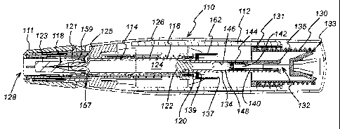
Figure 1 shows just such an injection device 110 in which a housing 112
contains a
hypodermic syringe 114. The syringe 114 is of conventional type, including a
syringe
body 116 terminating at one end in a hypodermic needle 118 and at the other in
a flange
120. The conventional plunger that would normally be used to discharge the
contents of
the syringe 114 manually have been removed and replaced with a drive element
134 as
will be described below, terminating in a bung 122. This drive element 134
constrains a
drug 124 to be administered within the syringe body 116. Whilst the syringe
illustrated is
of hypodermic type, this need not necessarily be so. Transcutaneous or
ballistic dermal
and subcutaneous syringes may also be used with the injection device of the
present
invention. Generally, the syringe must include a discharge nozzle, which in a
hypodermic
syringe is the needle 118.
As illustrated, the housing includes a return spring 126 that biases the
syringe 114 from
an extended position in which the needle 118 extends from an aperture 128 in
the housing
112 to a retracted position in which the discharge nozzle 118 is contained
within the
housing 112. The return spring 126 acts on the syringe 114 via a sleeve 127.
At the other end of the housing is a compression drive spring 130. Drive from
the drive
spring 130 is transmitted via a multi-component drive to the syringe 114 to
advance it
CA 02568647 2012-08-24
3
from its retracted position to its extended position and discharge its
contents through the
needle 118. The drive accomplishes this task by acting directly on the drug
124 and the
syringe 114. Hydrostatic forces acting through the drug and, to a lesser
extent, static
friction between the bung 122 and the syringe body 116 initially ensures that
they
advance together, until the return spring 126 bottoms out or the syringe body
116 meets
some other obstruction that retards its motion.
The multi-component drive between the drive spring 130 and the syringe 114
consists of
three principal components. A drive sleeve 131 takes drive from the drive
spring 130 and
transmits it to flexible latch arms 133 on a first drive element 132. This in
turn transmits
drive via flexible latch arms 135 to a second drive element, the drive element
134 already
mentioned.
The first drive element 132 includes a hollow stem 140, the inner cavity of
which forms a
collection chamber 142 in communication with a vent 144 that extends from the
collection chamber through the end of the stem 140. The second drive element
134
includes a blind bore 146 that is open at one end to receive the stem 140 and
closed at the
other. As can be seen, the bore 146 and the stem 140 define a fluid reservoir
148, within
which a damping fluid is contained.
A trigger (not shown) is provided at the middle of the housing 112 and, when
operated,
serves to decouple the drive sleeve 131 from the housing 112, allowing it to
move relative
to the housing 112 under the influence of the drive spring 130. The operation
of the
device is then as follows.
Initially, the drive spring 130 moves the drive sleeve 131, the drive sleeve
131 moves the
first drive element 132 and the first drive element 132 moves the second drive
element
134, in each case by acting through the flexible latch arms 133, 135. The
second drive
element 134 moves and, by virtue of static friction and hydrostatic forces
acting through
the drug 124 to be administered, moves the syringe body 116 against the action
of the
return spring 126. The return spring 126 compresses and the hypodermic needle
118
emerges from the exit aperture 128 of the housing 112. This continues until
the return
spring 126 bottoms out or the syringe body 116 meets some other obstruction
that retards
CA 02568647 2012-08-24
4
its motion. Because the static friction between the second drive element 134
and the
syringe body 116 and the hydrostatic forces acting through the drug 124 to be
administered are not sufficient to resist the full drive force developed by
the drive spring
130, at this point the second drive element 134 begins to move within the
syringe body
116 and the drug 124 begins to be discharged.
Dynamic friction between the second drive element 134 and the syringe body 116
and
hydrostatic forces acting through the drug 124 to be administered are,
however, sufficient
to retain the return spring 126 in its compressed state, so the hypodermic
needle 118
remains extended.
Before the second drive element 134 reaches the end of its travel within the
syringe body
116, so before the contents of the syringe have fully discharged, the flexible
latch arms
135 linking the first and second drive elements 132, 134 reach a constriction
137. The
constriction 137 is formed by a component 162 that is attached to the syringe
flange 120,
so it will be understood that when the syringe 114 advances from its retracted
position to
its extended position, the component 162 advances with it. The constriction
137 moves
the flexible latch arms 135 inwards from the position shown to a position at
which they
no longer couple the first drive element 136 to the second drive element 134,
aided by the
bevelled surfaces on the constriction 137. Once this happens, the first drive
element 136
acts no longer on the second drive element 134, allowing the first drive
element 132 to
move relative to the second drive element 134.
One drawback associated with this arrangement is that the latch arms 135 are
flexed by a
constriction 137 through which the drive elements must pass, and which can
therefore, at
best, flex the latch arms 135 so that their outer extremities coincide with
the outer surface
of the second drive element 134. As the first and second drive elements 132,
to move
relative to each other, the latch arms 135 must flex further, so that their
outer extremities
coincide with the inner surface of the second drive element 134. This
requirement
introduces manufacturing difficulties and may also affect the reliability of
the unlatching
mechanism itself.
CA 02568647 2012-08-24
Because the damping fluid is contained within a reservoir 148 defined between
the end of
the first drive element 132 and the blind bore 146 in the second drive element
134, the
volume of the reservoir 148 will tend to decrease as the first drive element
132 moves
relative to the second drive element 134 when the former is acted upon by the
drive
5 spring 130. As the reservoir 148 collapses, damping fluid is forced
through the vent 144
into the collection chamber 142. Thus, once the flexible latch arms 135 have
been
released, the force exerted by the drive spring 130 does work on the damping
fluid,
causing it to flow through the constriction formed by the vent 144, and also
acts
hydrostatically through the fluid and through friction between the first and
second drive
element 132,134, to drive the second drive element 134. Losses associated with
the flow
of the damping fluid do not attenuate the force acting on the body of the
syringe to a great
extent. Thus, the return spring 126 remains compressed and the hypodermic
needle 118
remains extended.
After a time, the second drive element 134 completes its travel within the
syringe body
116 and can go no further. At this point, the contents of the syringe 114 are
completely
discharged and the force exerted by the drive spring 130 acts to retain the
second drive
element 134 in its terminal position and to continue to cause the damping
fluid to flow
through the vent 144, allowing the first drive element 132 to continue its
movement.
Before the reservoir 148 of fluid is exhausted, the flexible latch arms 133
linking the
drive sleeve 131 with the first drive element 132 reach another constriction
139, also
provided by the component 162 that is attached to the syringe flange 120. The
constriction 139 moves the flexible latch arms 133 inwards from the position
shown to a
position at which they no longer couple the drive sleeve 131 to the first
drive element
132, aided by the bevelled surfaces on the constriction 139. Once this
happens, the drive
sleeve 131 acts no longer on the first drive element 132, allowing them to
move relative
to each other.
The latch arms 133 must be capable of supporting high shock load at the start
of stroke,
but must also be capable of releasing with relatively low unlatching forces.
Tests have
shown that this dual requirement is very difficult to achieve with flexible
latch arms 133:
CA 02568647 2012-08-24
6
if the latch arms are made stiff enough to carry the shock load, they may
easily became
too stiff to unlatch with acceptably small forces.
Once the drive sleeve 131 is acting no longer on the first drive element 132,
of course, the
syringe 114 is released, because the force developed by the drive spring 130
is no longer
being transmitted to the syringe 114, and the only force acting on the syringe
will be the
return force from the return spring 126. Thus, the syringe 114 now returns to
its retracted
position and the injection cycle is complete.
All this takes place only once the cap 111 has been removed from the end of
the housing
112 and the boot 123 from the syringe.
Summary of the Invention
As discussed above, there are two shortcomings in the design illustrated in
figure 1. The
first is that to enable the first and second drive elements to move relative
to each other,
the latch arms must flex further than they are flexed by the constriction
through which
they are caused to pass. This requirement introduces manufacturing
difficulties and may
also affect the reliability of the unlatching mechanism itself It is an
objective of the
present invention to provide an improved drive coupling and unlatching
mechanism that
does not suffer from this shortcoming.
Accordingly, the present invention provides a releasable drive coupling
comprising:
a first drive element having a first projecting flexible arm; and
a second drive element being slidable relative to the first drive element and
having:
a drive surface adapted to receive the first flexible arm, to allow axial
loads to be transmitted from one drive element to the other; and
a second projecting flexible arm so positioned relative to the drive surface
that inward flexing of the second flexible arm causes it to act upon the first
flexible arm
and flex the latter to a point at which it is no longer received by the drive
surface, at
which point the first and second drive elements are free to slide relative to
one another
and the drive coupling is thus disengaged.
CA 02568647 2012-08-24
7
It will immediately be seen that, owing to the use of the first flexible arms
to flex the
second flexible arms, there is no longer any need for the second flexible arms
to flex
further as the drive elements move relative to each other.
Preferably, the first flexible arms operate in compression to transmit axial
loads from one
drive element to the other. This deals with one problem of using flexible arms
under
tension, which can be difficult to delatch, needing a relatively high
delatching force. An
arm in compression provides a good ratio of carrying load to delatching load
and is a
stable configuration.
For convenience, the coupling may be arranged as follows:
the first drive element is an inner drive element;
the first flexible arm projects outwardly from the inner drive element;
the second drive element is an outer drive element capable of sliding over the
inner drive element;
the second flexible arm projects outwardly from the outer drive element; and
inward flexing of the second flexible arm causes it to flex the first flexible
arm
inwardly.
Preferably, the outer drive element has a bore in which the inner drive
element is
received. The inner drive element may have a plurality of outwardly
projecting, inner
flexible arms and the outer drive element a corresponding plurality of drive
surfaces and a
corresponding plurality of outwardly projecting, outer flexible arms. For
reasons of
symmetry, such outwardly projecting, inner and outer flexible arms may be
substantially
equidistantly spaced around the circumference of the inner drive element.
A simple extension of the present invention provides an automatically
releasable drive
coupling comprising:
a releasable drive coupling according to the invention;
an actuator acting upon one of the drive components; and
a decoupling component so arranged that, as the outer drive element is
advanced
by the actuator, it flexes the outer flexible arm inwardly, automatically
disengaging the
drive coupling.
CA 02568647 2012-08-24
8
The decoupling component may comprise a channel through which the inner and
outer
drive elements pass when acted upon by the actuator, the channel being so
arranged that,
as the outer drive element passes through it, it flexes the outer flexible arm
inwardly,
automatically disengaging the drive coupling.
In its application to an injection device, the present invention provides: a
housing adapted
to receive a syringe having a discharge nozzle, the housing including means
for biasing
the syringe from an extended position in which the discharge nozzle extends
from the
housing to a retracted position in which the discharge nozzle is contained
within the
housing;
an automatically releasable drive coupling according to the invention in
which:
the inner drive element is acted upon by the actuator and the outer drive
element acts upon the syringe to advance it from its retracted position to its
extended
position and discharge its contents through the discharge nozzle; and
the decoupling component automatically disengages the drive coupling
when the drive elements have been advanced to a nominal decoupling position.
The second drawback associated with the arrangement of figure 1 is that the
dual
requirement of stiffness and flexibility in the latch arms coupling the
actuator to the first
drive element is difficult to meet. It is a further objective of the present
invention to
obviate that requirement. Accordingly, a second aspect of the present
invention provides
an injection device comprising:
a housing adapted to receive a syringe having a discharge nozzle, the housing
including means for biasing the syringe from an extended position in which the
discharge
nozzle extends from the housing to a retracted position in which the discharge
nozzle is
contained within the housing;
an actuator;
first and second drive elements, of which the first is acted upon by the
actuator
and in turn acts upon the second, and the second acts upon the syringe to
advance it from
its retracted position to its extended position and discharge its contents
through the
discharge nozzle, the first drive element being capable of movement relative
to the second
when the first is acted upon by the actuator and the second is restrained by
the syringe;
of the actuator and the first drive element, one comprises a flexible arm that
CA 02568647 2012-08-24
9
engages with a second drive surface on the other, allowing the actuator to act
upon the
first drive element and preventing the former from moving relative to the
latter; and
the second drive element comprises a stop that prevents the flexible arm
disengaging from the drive surface until the first drive element has been
advanced to a
nominal release position relative to the second, whereupon the flexible arm
disengages
from the second drive surface, allowing the actuator to move relative to the
first drive
element and thus releasing the syringe from the action of the actuator,
whereupon the
biasing means restores the syringe to its retracted position.
By the same token, there is also provided an injection device comprising:
a housing adapted to receive a syringe having a discharge nozzle, the housing
including means for biasing the syringe from an extended position in which the
discharge
nozzle extends from the housing to a retracted position in which the discharge
nozzle is
contained within the housing;
an actuator;
a drive, acted upon by the actuator and acting upon the syringe to discharge
its
contents through the discharge nozzle; and
of the actuator and the drive, one comprises a flexible arm that engages with
a
drive surface on the other, allowing the actuator to act upon the drive and
preventing the
former from moving relative to the latter;
in which the flexible arm is prevented from disengaging from the drive surface
until the drive has been advanced to a nominal release position, whereupon the
flexible
arm disengages from the drive surface, allowing the actuator to move relative
to the drive
and thus releasing the syringe from the action of the actuator, whereupon the
biasing
means restores the syringe to its retracted position.
The use of a stop to restrain the flexible arm and prevent its disengagement
from the drive
surface means that it need not be made as stiff as was the case with figure 1.
Hence a
more flexible material can be used and the shortcomings associated with the
arrangement
of figure 1 are avoided.
CA 02568647 2012-08-24
Preferably, the action of the actuator on the first drive element tends to
disengage the
flexible arm from the drive surface, but is prevented from doing so by the
stop until the
said nominal release position has been reached.
In a convenient implementation of this aspect of the invention, the second
flexible arm
5 includes a detent and the stop is in register with the detent when the
said nominal release
position is reached, thus allowing the flexible arms to flex. Preferably, the
second flexible
arm is biased toward a position at which it engages the second drive surface
and the
action of the actuator causes it to move against its bias, thus disengaging it
from the drive
surface.
10 Figure 2 shows an injection device 210 in which a housing 212 contains a
hypodermic
syringe 214. The syringe 214 is again of conventional type, including a
syringe body 216
terminating at one end in a hypodermic needle 218 and at the other in a flange
220, and a
rubber bung 222 that constraints a drug 224 to be administered within the
syringe body
216. The conventional plunger that would normally be connected to the bung 222
and
used to discharge the contents of the syringe 214 manually, has been removed
and
replaced with a multi-component drive element as will be described below.
Whilst the
syringe illustrated is again of hypodermic type, this need not necessarily be
so. As
illustrated, the housing includes a return spring 226 that biases the syringe
214 from an
extended position in which the needle 218 extends from aperture 228 in the
housing 212,
to a retracted position in which the hypodermic needle 218 is contained within
the
housing 212. The return spring 226 acts on the syringe 214 via a sleeve 227.
At the other end of the housing is a compression drive spring 230. Drive from
the drive
spring 230 this transmitted via the multi-component drive to the syringe 214
to advance it
from its retracted position to its extended position and discharge its
contents through the
needle 218. The drive accomplishes this task by acting directly on the drug
224 and the
syringe 214. Hydrostatic forces acting through the drug and, to a lesser
extent, static
friction between the bung 222 and the syringe body 216 initially ensures that
they
advance together, until the return spring 226 bottoms out or the syringe body
216 meets
some other obstruction that retards its motion.
CA 02568647 2012-08-24
11
The multi component drive between the drive spring 230 and the syringe 214
again
consists of three principal components. The drive sleeve 231 takes drive from
the drive
spring 230 and transmits it to flexible latch arms 233 on a first drive
element 232. These
elements are shown in detail "A". The first drive element 232 in turn
transmits drive via
flexible latch arms 235 to a second drive element 234. These elements are
shown in detail
"B". As before, the first drive element 232 includes a hollow stem 240, the
inner cavity of
which forms a collection chamber 242. The second drive element 234 includes a
blind for
246 that is open at one end to receive the stem 240 and closed at the other.
As can be
seen, the bore 246 and the stem 240 define a fluid reservoir 248, within which
a damping
fluid is contained.
A trigger (not shown) is provided at the middle of the housing 212 and, one
operated,
serves to decouple the drive sleeve 231 from the housing 212 allowing it to
move relative
to the housing 212 under the influence of the drive spring 230. The operation
of the
device is then as follows.
Initially, the drive spring 230 moves the drive sleeve 231, the drive sleeve
231 moves the
first drive element 232 and the first drive element 232 moves the second drive
element
234, in each case by acting through the flexible matching arms 233,235. The
second drive
element 234 moves and, by virtue of static friction and hydrostatic forces
acting through
the drug 224 to be administered, moves the syringe body 216 against the action
of the
return spring 226. The return spring 226 compresses and the hypodermic needle
218
emerges from the exit aperture 228 of the housing 212. This continues until
the return
spring 226 bottoms out or the syringe body 216 meets some other obstruction
that retards
its motion. Because the static friction between the bung 222 and the syringe
body 216 and
the hydrostatic forces acting through the drug 224 to be administered are not
sufficient to
resist the full drive force developed by the drive spring 230, at this point
the second drive
element 234 begins to move within the syringe body 216 and the drug 224 begins
to be
discharged. Dynamic friction between the bung 222 and the syringe body 216 and
hydrostatic forces acting through the drug 224 to be administered are,
however, sufficient
to retain the return spring 226 in its compressed state, so the hypodermic
needle 218
remains extended.
CA 02568647 2012-08-24
12
Before the second drive element 234 reaches the end of its travel within the
syringe body
216, so before the contents of the syringe have fully discharged, the flexible
latch arms
235 linking the first and second drive elements 232,234 reach a constriction
237. The
constriction 237 is formed by a component 262 that is initially free to move
relative to all
other components, but that is constrained between the syringe flange 220 and
additional
flexible arms 247 on the second drive element 234. These additional flexible
arms 247
overlie the flexible arms 235 on the first drive element 232, by means of
which drive is
transmitted to the second drive element 234. Figure 2 illustrates the
injection device 210
at the position where the additional flexible arms 247 are just making contact
with the
constriction 237 in the component 262.
The constriction 237 moves the additional flexible arms 247 inwards, aided by
the
bevelled surfaces on both, and the additional flexible arms 247 in turn move
the flexible
arms 235, by means of which drive is transmitted from the first drive element
232 to the
second drive element 234, inwards from the position shown to a position at
which they no
longer couple the first and second drive elements together. Once this happens,
the first
drive element 232 acts no longer on the second drive element 234, allowing the
first drive
element 232 to move relative to the second drive element 234.
Because the damping fluid is contained within a reservoir 248 defined between
the end of
the first drive element 232 and the blind bore 246 in the second drive element
234, the
volume of the reservoir 248 will tend to decrease as the. first drive element
232 moves
relative to the second drive element 234 when the former is acted upon by the
drive
spring 230. As the reservoir 248 collapses, damping fluid is forced into the
collection
chamber 242. Thus, once the flexible latch arms 235 have been released, the
force exerted
by the drive spring 230 does work on the damping fluid, causing it to flow
into the
collection chamber 242, and also acts hydrostatically through the fluid and
through
friction between the first and second drive elements 232,234, thence via the
second drive
element 234. Losses associated with the flow of the damping fluid do not
attenuate the
force acting on the body of the syringe to a great extent. Thus, the return
spring 226
remains compressed and the hypodermic needle remains extended.
CA 02568647 2012-08-24
13
After a time, the second drive element 234 completes its travel within the
syringe body
216 and can go no further. At this point, the contents of the syringe 214 are
completely
discharged and the force exerted by the drive spring 230 acts to retain the
second drive
element 234 in its terminal position and to continue to cause the damping
fluid to flow
into the collection chamber 142, allowing the first drive element 232 to
continue its
movement.
A flange 270 on the rear of the second drive element 234 normally retains the
flexible
arms 233 in engagement with the drive sleeve 231. However, before the
reservoir 248 of
fluid is exhausted, the flexible latch arms 233 linking the drive sleeve 231
with the first
drive element 232 move sufficiently far forward relative to the second drive
element 234
that the flange 270 is brought to register with a rebate 272 in the flexible
arms 233,
whereupon it ceases to be effective in retaining the flexible arms 233 in
engagement with
the drive sleeve 231. Now, the drive sleeve 231 moves the flexible latch arms
233
inwards from the position shown to a position at which they no longer couple
the drive
sleeve 231 to the first drive element 232, aided by the bevelled latching
surfaces 274 on
the flexible arms 233. Once this happens, the drive sleeve 231 acts no longer
on the first
drive element 232, allowing them to move relative to each other. At this
point, of course,
the syringe 214 is released, because the forces developed by the drive spring
230 are no
longer being transmitted to the syringe 214, and the only force acting on the
syringe will
be the return force from the return spring 226. Thus, the syringe 214 now
returns to its
retracted position and the injection cycle is complete.