Language selection

Search

Patent 2568699 Summary

Third-party information liability

Some of the information on this Web page has been provided by external sources. The Government of Canada is not responsible for the accuracy, reliability or currency of the information supplied by external sources. Users wishing to rely upon this information should consult directly with the source of the information. Content provided by external sources is not subject to official languages, privacy and accessibility requirements.

Claims and Abstract availability

Any discrepancies in the text and image of the Claims and Abstract are due to differing posting times. Text of the Claims and Abstract are posted:

  • At the time the application is open to public inspection;
  • At the time of issue of the patent (grant).
(12) Patent Application: (11) CA 2568699
(54) English Title: BRAKE MECHANISM
(54) French Title: SYSTEME DE FREINAGE
Status: Deemed Abandoned and Beyond the Period of Reinstatement - Pending Response to Notice of Disregarded Communication
Bibliographic Data
(51) International Patent Classification (IPC):
  • F16D 55/00 (2006.01)
(72) Inventors :
  • BAUMGARTNER, JOHANN (Germany)
  • SAGERER, STEFAN (Germany)
  • MAUZ, UWE (Germany)
(73) Owners :
  • KNORR-BREMSE SYSTEME FUR NUTZFAHRZEUGE GMBH
  • DAIMLERCHRYSLER AG
(71) Applicants :
  • KNORR-BREMSE SYSTEME FUR NUTZFAHRZEUGE GMBH (Germany)
  • DAIMLERCHRYSLER AG (Germany)
(74) Agent: SMART & BIGGAR LP
(74) Associate agent:
(45) Issued:
(86) PCT Filing Date: 2005-03-24
(87) Open to Public Inspection: 2005-10-13
Availability of licence: N/A
Dedicated to the Public: N/A
(25) Language of filing: English

Patent Cooperation Treaty (PCT): Yes
(86) PCT Filing Number: PCT/EP2005/003155
(87) International Publication Number: WO 2005095815
(85) National Entry: 2006-11-29

(30) Application Priority Data:
Application No. Country/Territory Date
10 2004 016 826.1 (Germany) 2004-04-01

Abstracts

English Abstract


Disclosed is a brake mechanism comprising a connecting element (1) that is
fixed to a wheel axle of a motor vehicle or is embodied monolithically
therewith, and a fastening flange (3) of a disk brake caliper (2), said
fastening flange (3) being fixed to the connecting element (1). The inventive
brake mechanism is configures in such a way that the fastening flange (3) is
retained in a positive manner on the connecting element (1) in the
circumferential direction of the wheel axle.


French Abstract

La présente invention concerne un système de freinage comprenant un corps de raccord (1) qui est fixé sur un essieu de roues d'un véhicule automobile ou forme une seule pièce avec celui-ci, et une bride de fixation (3) d'un étrier de frein (2) d'un frein à disque, la bride de fixation (3) étant fixée au corps de raccord (1). Le système de freinage est conçu de sorte que la bride de fixation (3) est maintenue dans la direction périphérique de l'essieu de roues, par liaison de forme contre le corps de raccord (1).

Claims

Note: Claims are shown in the official language in which they were submitted.

-8-
Claims
1. A brake mechanism, having a connecting element (1)
which is fastened to a wheel axle of a motor vehicle or is
configured in one piece with the latter, and a fastening
flange (3) of a brake caliper (2) or a brake carrier of a
disk brake, the fastening flange (3) being fastened to the
connecting element (1), characterized in that the
fastening flange (3) is held in a form-fitting manner on
the connecting element (1) in the circumferential
direction of the wheel axle.
2. The brake mechanism as claimed in claim 1,
characterized in that the fastening flange (3) and the
connecting element (1) have in each case contact faces (6)
which bear against one another and extend in each case at
an acute angle a of less than 90° with respect to the
center longitudinal axis of the connecting element (1).
3. The brake mechanism as claimed in claim 1 or 2,
characterized in that the contact faces (6) are arranged
so as to extend in a V shape with respect to one another.
4. The brake mechanism as claimed in one of the
preceding claims, characterized in that the contact faces
(6) are arranged in a mirror-symmetrical manner about the
center longitudinal axis (L) of the connecting element (1)
with respect to one another.
5. The brake mechanism as claimed in one of the
preceding claims, characterized in that the connecting
element (1) has two connecting limbs (4), the sides of
which which face the fastening flange (3) form in each
case the contact face (6).
6. The brake mechanism as claimed in one of the
preceding claims, characterized in that each connecting

- 9 -
limb (4) has supporting faces which extend parallel with
respect to the associated contact face (6) and on which
heads of connection screws (5) are supported, which
connection screws (5) are screwed into the fastening
flange (3).
7. The brake mechanism as claimed in one of the
preceding claims, characterized in that the connection
screws (5) are arranged so as to extend tangentially with
respect to the wheel axle.
8. The brake mechanism as claimed in one of the
preceding claims, characterized in that the fastening
flange (3) is provided with two fastening limbs (8), of
which each is assigned to a connecting limb (4) of the
connecting element (1) and bears against the contact face
(6).
9. The brake mechanism as claimed in one of the
preceding claims, characterized in that each fastening
limb (8) bears over its full surface area against the
contact face (6) of the associated connecting limb (4).
10. The brake mechanism as claimed in one of the
preceding claims, characterized in that the contact faces
(6) enclose an angle 2a of less than 90° with respect to
the center longitudinal axis (L) of the connecting element
(10), in particular between 20° and 70°, preferably from
30° to 60°.
11. The brake mechanism as claimed in one of the
preceding claims, characterized in that the contact faces
(6) enclose an angle 2a of approximately 55 , in
particular 58°.

-10-
12. The brake mechanism as claimed in one of the
preceding claims, characterized in that the connecting
element (10) is formed in one piece as a cast part with
the wheel axle or with an axle element.

Description

Note: Descriptions are shown in the official language in which they were submitted.


CA 02568699 2006-11-29
WO 2005/095815 PCT/EP2005/003155
Brake mechanism
The present invention relates to a brake mechanism in
accordance with the preamble of claim 1.
Preferably disk brakes which are actuated by compressed
air, in particular for commercial vehicles, are fastened
in each case to a connecting element which is connected
fixedly to the wheel axle by a fastening flange of the
brake caliper or a brake carrier of the disk brake being
screwed to the connecting element.
This type of fastening is shown and described, for
example, in EP 0 849 486 A2. Here, the connecting element
and the fastening flange of the brake caliper bear with
their full surface area against one another, that is to
say in an overlapping manner, and are screwed to one
another by screws which extend in the axial direction of
the wheel axle.
Although satisfactory positioning of the brake caliper is
achieved as a result, the exclusively force-transmitting
connection is associated with some disadvantages which
stand in the way of long-term optimum operation of the
disk brake.
During the braking operation, a torque becomes active as a
result of the applied braking force or as a result of the
friction forces which act on the brake disk, which torque
has to be absorbed by the screw connections which in each
case comprise a through hole, a threaded hole and a screw,
it being possible for the through hole to be provided in
the connecting element or fastening flange and for the
threaded hole to be provided in the other associated
component.

CA 02568699 2006-11-29
- 2 -
In order for the screw to pass through, the diameter of
the through whole has to be greater than the shaft
diameter of the screw. In particular in the case of high
braking moments which are not transmitted by the force-
transmitting connection, this leads to a relative movement
of the component which has the through hole with respect
to the other components, until the interior of the through
hole comes into contact with the screw shaft. As a result,
the screws are subjected to shear forces to a considerable
extent, which makes corresponding cross-sectional
dimensioning necessary which counteracts inexpensive
mounting and a weight-optimized construction.
It is also problematic that this type of connection
requires a relatively large number of connection screws,
which necessitates large bearing faces of the connecting
element and the fastening flange.
As a result of the abovementioned relative displacement of
the components which are connected to one another during
braking, the sliding guide of the brake caliper in a
sliding caliper brake can be stressed, which leads to
long-term damage of the guide parts. Moreover, in the case
of reversing operation, the frequent to and fro
displacement of the components can lead to loosening of
the screws, as a result of which the operational security
can be impaired overall.
One further disadvantage of the known fastening type is
the poor accessibility of the screws; as screwing has to
take place from the vehicle inner side, mounting and
dismantling of the brake is made difficult.
It is known from DE 200 21 587 U1 not to arrange the
screws coaxially with respect to the rotational axis of
the disk brake, but tangentially with respect thereto.
Although this construction makes improved accessibility of

CA 02568699 2006-11-29
- 3 -
the screws possible during mounting and a reduction in the
brake weight as a result of the possible smaller bearing
faces of the connecting element and the fastening flange,
the relative displaceability of the two components with
respect to one another during the transmission of the
braking moments to the axle still exists, with the above-
described disadvantages.
The present invention is therefore based on the object of
developing a brake mechanism of the generic type in such a
way that it can be manufactured and mounted or dismantled
inexpensively, weight reduction of the brake overall is
achieved and the operational security is improved.
This object is achieved by a brake mechanism which has the
features of claim 1.
As a result of this structural configuration, the braking
moment is now absorbed by a form-fitting connection and
not, as in the prior art, by a force-transmitting
connection. Relative displacement of the fastening flange
with respect to the connecting element is therefore
precluded.
This results first of all in an improvement in the
operational security, as, for example in the case of a
sliding caliper brake, the guide parts can no longer be
stressed with respect to one another and, during reversing
operation, loosening of connection screws is precluded.
As they no longer serve to accommodate the screws, but
exclusively for the form-fitting connection, the contact
faces of the two components can be kept relatively small,
which contributes to a weight saving and to the
optimization of manufacturing. The same is true
analogously for the reduced number of connections screws

CA 02568699 2006-11-29
_ 4 _
which is then possible, as these in practice serve only to
hold the two components against one another.
The associated reduction in the space requirement makes
substantially improved accessibility to the screws
possible, with the result that mounting and dismantling of
the brake is possible in a substantially simpler manner.
According to one advantageous development of the
invention, there is provision for the contact faces of the
fastening flange on one side and of the connecting element
on the other side to extend in a manner which is oriented
obliquely toward the center of the wheel axle, with the
result that the respective two contact faces lie in a V
shape with respect to one another. Here, the fastening
flange in practice forms a wedge which is supported
laterally on the connecting elements.
During brake mounting, this V shape makes simple,
predefined positioning possible, which likewise simplifies
mounting.
Further advantageous refinements of the invention are
characterized in the subclaims.
In the following text, one exemplary embodiment of the
invention will be described using the appended drawing.
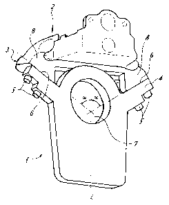
The single figure shows a brake mechanism according to the
invention in a perspective illustration.
The figure shows a brake mechanism which, in its basic
construction, comprises a connecting element 1, a
fastening flange 3 and a brake caliper 2 which is formed
here in one piece with the latter.

CA 02568699 2006-11-29
- 5 -
The connecting element 1 is fastened to a wheel axle (not
shown), for example by welding, for which purpose the
connecting element 1 has a push-in bore 7, in order to
accommodate the wheel axle. In one design variant, the
connecting element 1 can be configured in one piece with
the axle body as a cast part or forging.
Overall, the connecting element 1 is of plate-shaped and,
here, mirror-symmetrical configuration. Connecting limbs 4
are formed on both sides, which lie in a V shape with
respect to one another and have contact faces 6, against
which fastening limbs 8 of the fastening flange 3 bear.
Accordingly, the fastening limbs 8 likewise together form
a V shape, in relation to the faces which face the contact
faces 6. The V has an opening angle a with respect to the
center longitudinal axis L of the connecting element. The
center longitudinal axis L extends through the tip of the
V.
In principle, every angle which is less than 90 is
conceivable, below which the respective contact face 6 is
oriented toward the center longitudinal axis of the
connecting element 1. The contact faces 6 preferably lie
in each case at an angle 2a of from 10 to 80 with respect
to one another, preferably from 30 to 60 , in particular
approximately 55 , with very particular preference 58 , as
results which are improved further can be achieved in each
case in a surprising manner at these angles.
The fastening limbs 8 and therefore the brake caliper 2
are connected to the connecting element 1 by connection
screws 5 which extend preferably tangentially with respect
to the wheel axle or with respect to the push-in bore 7,
the heads of the connection screws 5 being supported on
supporting faces of the connecting limbs 4, which
supporting faces extend parallel with respect to the
respective contact face 6.

CA 02568699 2006-11-29
- 6 -
As can be seen clearly, the connecting limbs 4 form an
abutment for absorbing braking moments which occur and are
active in the circumferential direction of the push-in
bore 7 or the wheel axle (not shown). Shear loading of the
connection screws 5 is precluded here.

CA 02568699 2006-11-29
WO 2005/095815 PCT/EP2005/003155
- 7 -
List of designations
1 Connecting element
2 Brake caliper
3 Fastening flange
4 Connecting limb
Connection screw
6 Contact face
7 Push-in bore
8 Fastening limb

Representative Drawing
A single figure which represents the drawing illustrating the invention.
Administrative Status

2024-08-01:As part of the Next Generation Patents (NGP) transition, the Canadian Patents Database (CPD) now contains a more detailed Event History, which replicates the Event Log of our new back-office solution.

Please note that "Inactive:" events refers to events no longer in use in our new back-office solution.

For a clearer understanding of the status of the application/patent presented on this page, the site Disclaimer , as well as the definitions for Patent , Event History , Maintenance Fee  and Payment History  should be consulted.

Event History

Description Date
Application Not Reinstated by Deadline 2011-03-24
Time Limit for Reversal Expired 2011-03-24
Inactive: Abandon-RFE+Late fee unpaid-Correspondence sent 2010-03-24
Deemed Abandoned - Failure to Respond to Maintenance Fee Notice 2010-03-24
Letter Sent 2007-08-21
Inactive: Single transfer 2007-06-05
Inactive: Courtesy letter - Evidence 2007-02-06
Inactive: Cover page published 2007-02-02
Inactive: Notice - National entry - No RFE 2007-01-29
Application Received - PCT 2006-12-28
National Entry Requirements Determined Compliant 2006-11-29
Application Published (Open to Public Inspection) 2005-10-13

Abandonment History

Abandonment Date Reason Reinstatement Date
2010-03-24

Maintenance Fee

The last payment was received on 2009-03-11

Note : If the full payment has not been received on or before the date indicated, a further fee may be required which may be one of the following

  • the reinstatement fee;
  • the late payment fee; or
  • additional fee to reverse deemed expiry.

Please refer to the CIPO Patent Fees web page to see all current fee amounts.

Fee History

Fee Type Anniversary Year Due Date Paid Date
Basic national fee - standard 2006-11-29
Reinstatement (national entry) 2006-11-29
MF (application, 2nd anniv.) - standard 02 2007-03-26 2007-02-12
Registration of a document 2007-06-05
MF (application, 3rd anniv.) - standard 03 2008-03-25 2008-02-07
MF (application, 4th anniv.) - standard 04 2009-03-24 2009-03-11
Owners on Record

Note: Records showing the ownership history in alphabetical order.

Current Owners on Record
KNORR-BREMSE SYSTEME FUR NUTZFAHRZEUGE GMBH
DAIMLERCHRYSLER AG
Past Owners on Record
JOHANN BAUMGARTNER
STEFAN SAGERER
UWE MAUZ
Past Owners that do not appear in the "Owners on Record" listing will appear in other documentation within the application.
Documents

To view selected files, please enter reCAPTCHA code :


To view images, click a link in the Document Description column. To download the documents, select one or more checkboxes in the first column and then click the "Download Selected in PDF format (Zip Archive)" or the "Download Selected as Single PDF" button.

List of published and non-published patent-specific documents on the CPD .

If you have any difficulty accessing content, you can call the Client Service Centre at 1-866-997-1936 or send them an e-mail at CIPO Client Service Centre.


Document
Description 
Date
(yyyy-mm-dd) 
Number of pages   Size of Image (KB) 
Abstract 2006-11-29 1 12
Description 2006-11-29 7 215
Drawings 2006-11-29 1 14
Claims 2006-11-29 3 80
Representative drawing 2007-02-01 1 7
Cover Page 2007-02-02 1 36
Reminder of maintenance fee due 2007-01-29 1 111
Notice of National Entry 2007-01-29 1 205
Courtesy - Certificate of registration (related document(s)) 2007-08-21 1 104
Reminder - Request for Examination 2009-11-25 1 117
Courtesy - Abandonment Letter (Maintenance Fee) 2010-05-19 1 174
Courtesy - Abandonment Letter (Request for Examination) 2010-06-30 1 164
PCT 2006-11-29 5 165
Correspondence 2007-01-29 1 27