Language selection

Search

Patent 2569801 Summary

Third-party information liability

Some of the information on this Web page has been provided by external sources. The Government of Canada is not responsible for the accuracy, reliability or currency of the information supplied by external sources. Users wishing to rely upon this information should consult directly with the source of the information. Content provided by external sources is not subject to official languages, privacy and accessibility requirements.

Claims and Abstract availability

Any discrepancies in the text and image of the Claims and Abstract are due to differing posting times. Text of the Claims and Abstract are posted:

  • At the time the application is open to public inspection;
  • At the time of issue of the patent (grant).
(12) Patent Application: (11) CA 2569801
(54) English Title: BRAKE DISC ASSEMBLY FOR VEHICLE WHEELS
(54) French Title: SYSTEME DE FREIN A DISQUE POUR ROUES DE VEHICULE
Status: Deemed Abandoned and Beyond the Period of Reinstatement - Pending Response to Notice of Disregarded Communication
Bibliographic Data
(51) International Patent Classification (IPC):
  • F16D 65/00 (2006.01)
  • F16D 65/12 (2006.01)
(72) Inventors :
  • RAU, GUIDO (Germany)
  • HECKER, ANDREAS (Germany)
  • RIECK, TORSTEN (Germany)
(73) Owners :
  • GEORG FISCHER FAHRZEUGTECHNIK AG
(71) Applicants :
  • GEORG FISCHER FAHRZEUGTECHNIK AG (Switzerland)
(74) Agent: ROBIC AGENCE PI S.E.C./ROBIC IP AGENCY LP
(74) Associate agent:
(45) Issued:
(86) PCT Filing Date: 2005-08-30
(87) Open to Public Inspection: 2006-03-23
Examination requested: 2010-07-09
Availability of licence: N/A
Dedicated to the Public: N/A
(25) Language of filing: English

Patent Cooperation Treaty (PCT): Yes
(86) PCT Filing Number: PCT/EP2005/009311
(87) International Publication Number: WO 2006029705
(85) National Entry: 2006-12-04

(30) Application Priority Data:
Application No. Country/Territory Date
10 2004 045 327.6 (Germany) 2004-09-16

Abstracts

English Abstract


The invention relates to a brake disc assembly (1) for vehicle wheels,
comprising at least one friction ring (2, 3) and a wheel fixing zone (7) that
runs parallel to the friction ring (2, 3). Said friction ring (2, 3) and wheel
fixing zone (7) are configured in one-piece from a die-cast material and
connecting struts (6) are formed between the friction ring (2, 3) and the
wheel fixing zone. Said assembly is characterised in that the connecting
struts (6) are elastically sprung in a radial and axial direction.


French Abstract

La présente invention concerne un système de frein à disque (1) destiné à des roues de véhicule, comprenant au moins un anneau de frottement (2,3) et une zone de fixation à la roue (7) qui s'étend parallèlement à l'anneau de frottement (2,3). Selon l'invention, l'anneau de frottement (2,3) et la zone de fixation à la roue (7) sont réalisés en une seule pièce dans un matériau coulé, et des brides de liaison (6) sont formées entre l'anneau de frottement (2,3) et la zone de fixation à la roue. L'invention se caractérise en ce que les brides de liaison (6) sont réalisées pour exercer une force de rappel élastique en direction radiale et en direction axiale.

Claims

Note: Claims are shown in the official language in which they were submitted.

7
Claims
1. A brake disc assembly (1) for vehicle wheels,
comprising at least one friction ring (2,3) and a wheel
fixing zone (7) that runs parallel to the friction ring
(2,3), whereby the friction ring (2,3) and the wheel
fixing zone (7) are configured in one-piece form from a
cast material and whereby connecting struts (6) are
formed between the friction ring (2,3) and the wheel
fixing zone, characterized in that the connecting
struts (6) are spring-elastic in radial and/or axial
directions.
2. The brake disc assembly (1) as claimed in claim 1,
characterized in that the connecting struts (6) have an
undulating profile, whereby the connecting struts (6)
run through at least one complete wavelength in the
axial direction.
3. The brake disc assembly (1) as claimed in claim 1,
characterized in that the connecting struts (6) have an
undulating profile, whereby the connecting struts (6)
run through less than one complete wavelength in the
axial direction.
4. The brake disc assembly (1) as claimed in at least
one of claims 1 to 3, characterized in that one end of
the connecting struts (6) is connected to the rear
friction ring (3), viewed from the wheel fixing zone
(7).
5. The brake disc assembly (1) as claimed in at least
one of claims 1 to 4, characterized in that one end of
the connecting struts (6) is connected to the front
friction ring (2), viewed from the wheel fixing zone
(7).

8
6. The brake disc assembly (1) as claimed in at least
one of claims 1 to 5, characterized in that one end of
the connecting struts (6) is alternately connected with
the front friction ring (2) and the rear friction ring
(3), viewed from the wheel fixing zone (7).
7. The brake disc assembly (1) as claimed in at least
one of claims 1 to 6, characterized in that the
connecting struts (6) have a width (b) which is
substantially as wide as the space (s) which is
configured between two adjacent connecting struts.
8. The brake disc assembly (1) as claimed in at least
one of claims 1 to 7, characterized in that the
connecting struts (6) have a width (b) which is
substantially much wider than the space (s) which it
configured between two adjacent connecting struts.
9. The brake disc assembly (1) as claimed in at least
one of claims 1 to 8, characterized in that the
connecting struts (6) have a width (b) which widens
towards the friction rings (2,3), viewed from the wheel
fixing zone (7).
10. The brake disc assembly (1) as claimed in at least
one of claims 1 to 9, characterized in that the
connecting struts (6) run radially towards the friction
rings (2,3), viewed from the wheel fixing zone (7).
11. The brake disc assembly (1) as claimed in at least
one of claims 1 to 10, characterized in that the
connecting struts (6) run in a spiral towards the
friction rings (2,3), viewed from the wheel fixing zone
(7).

Description

Note: Descriptions are shown in the official language in which they were submitted.


CA 02569801 2006-12-04
WO 2006/029705 PCT/EP2005/009311
1
Brake Disc Assembly for Vehicle Wheels
The invention relates to a brake disc assembly for
vehicle wheels, comprising at least one friction ring
and a wheel fixing zone that runs parallel to the
friction ring, whereby the friction ring and the wheel
fixing zone are configured in one-piece form from a
cast material and whereby connecting struts are formed
between the friction ring and the wheel fixing zone.
Different designs of disc brakes are used in vehicle
manufacturing to reduce the kinetic energy of the
vehicle. The disc brake comprises at least one disc or
a friction ring and the corresponding brake shoes and
is generally installed between the wheel and the wheel
bearing. When the wheels are driven, the brake
configuration can be combined with the wheel support.
The friction between the friction rings and the brake
shoes converts the kinetic energy into thermal energy.
The friction rings can in the process reach very high
temperatures of up to approximately 850 C. Under the
influence of the peripheral speed and of the
temperature, the friction rings can deform in a plate-
like manner, because they are connected to the wheel
only on the inside of the ring. The deformations cause
the friction rings to become uneven, which often leads
to unpleasant audible brake noises. It is desirable to
either reduce or silence these brake noises.
Furthermore, the deformations lead to irregular wear of
the brake pads.
A generic brake disc assembly is known from EP 1 233
201-A2. The assembly comprises two friction rings that
are arranged in parallel and at a distance from one
another. A support element is arranged concentrically
to the friction rings. The support element is
configured in a pot-shaped manner and comprises a
fixing zone for the wheel or the rim and a receiving

CA 02569801 2006-12-04
WO 2006/029705 PCT/EP2005/009311
2
zone fo~f receiving the wheel bearing. The support
element is connected to the friction rings via struts.
The support element, the struts, and the friction rings
are manufactured from a cast. The one end of the strut
is connected to the wheel bearing receiving zone and
the other end is connected to at least two ribs that
are arranged between the friction rings so as to run
radially. The central zone of the strut runs at an
angle a to the plane of the friction ring. The angle a
is to be calculated on the basis of the stress during a
braking process.
Based on this state of the art, it is the object of the
invention to disclose a brake disc assembly that is
simple to produce and wherein the friction rings are
deformed as little as possible.
This object is achieved by means of a brake disc
assembly for vehicle wheels, comprising at least one
friction ring and a wheel fixing zone that runs
parallel to the friction ring, whereby the friction
ring and the wheel fixing zone are configured in one-
piece form from a cast material and whereby connecting
struts are formed between the friction ring and the
wheel fixing zone, whereby the connecting struts are
spring-elastic in the radial and/or axial directions.
Preferred embodiments of the invention result from the
dependent claims.
It is advantageous that, during the braking process,
the brake disc assembly has the largest possible room
to move. This is achieved by the connecting struts
having an undulating profile, whereby the connecting
struts run through at least one complete wavelength in
the axial direction.
It is also advantageous that the brake disc assembly is

CA 02569801 2006-12-04
WO 2006/029705 PCT/EP2005/009311
3
constructed as compactly as possible. This is achieved
by one end of the connecting struts being connected to
the rear friction ring, viewed from the wheel fixing
zone.
An exemplary embodiment of the invention is described
by means of the figures. In said figures:
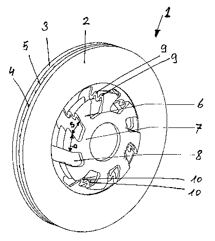
Figure 1 is a perspective view onto a brake disc
assembly as claimed in the invention,
Figure 2 is a perspective view onto a partial area of a
further brake disc assembly as claimed in the
invention,
Figure 3 shows a section through a partial area of the
brake disc assembly of Figure 2,
Figure 4 is a perspective view onto a partial area of a
further brake disc assembly as claimed in the
invention,
Figure 5 shows a section through a partial area of the
brake disc assembly of Figure 4,
Figure 6 is a perspective view onto a partial area of a
further brake disc assembly as claimed in the
invention, and
Figure 7 shows a section through a partial area of the
brake disc assembly of Figure 6.
Figure 1 schematically illustrates a brake disc
assembly 1 for vehicle wheels. The brake disc assembly
1 comprises two friction rings 2,3 which are embodied
as ring discs that run parallel and are connected to
one another by means of ribs 4. During each braking
process, the brake shoes act on the outside of the

CA 02569801 2006-12-04
WO 2006/029705 PCT/EP2005/009311
4
friction rings 2,3 with the brake pads (not illustrated
herein). Large through openings 5 are left open between
the ribs 4. As a result, the space between the friction
rings 2,3 largely remains open for the air that can
flow from the inside to the outside through the through
openings 5. After each braking process, the outside and
the inside of the friction rings 2,3 can thus be
cooled.
Connecting struts 6 are configured on the side of the
friction rings 2,3 having the smaller diameter, i.e.
the inner diameter. The connecting struts 6 serve to
connect the friction rings 2,3 to a wheel fixing zone 7
for the vehicle wheel that is also not illustrated
herein. The wheel fixing zone 7 can be configured as a
flange that has holes for the wheel fixing screws. A
hub or an area for receiving the wheel bearing can also
be configured between the wheel fixing zone 7 and the
connecting struts 6. The wheel receiving zone then runs
parallel to the wheel axis and the wheel fixing zone 7
runs perpendicular thereto, i.e. parallel to the
braking surfaces of the friction rings 2,3.
The wheel fixing zone 7, the wheel bearing receiving
zone, the connecting struts 6, and the friction rings
2,3 are produced as a cast molded part made from a
cast. Spaces 8 are visible between the connecting
struts 6. It can be seen from Figure 1 that the spaces
8 have a width s that is approximately as wide as the
width b of the connecting struts 6. The connecting
struts 6 have an undulating profile. In Figure 1, the
connecting struts 6 run through two complete
wavelengths in the axial direction. The connecting
struts 6 have alternate recesses 9, 10. A respective
inwardly-directed recess 10 follows an outwardly
directed recess 9. When, as in Figure 1, the undulating
profile runs through two complete wavelengths, two
recesses 9 are configured on the outside and two

CA 02569801 2006-12-04
WO 2006/029705 PCT/EP2005/009311
recesses 10 are configured on the inside of the
connecting struts 6. Undulating profiles with a
plurality of wavelengths that have been completely run
through or with less than one wavelength are also
possible.
Figure 2 and Figure 3 illustrate a further exemplary
embodiment of the brake disc assembly 1 as claimed in
the invention. The spaces 8 between the connecting
struts 6 have a considerably smaller width s than in
Figure 1. The connecting struts 6 have a width b that
is at least twice as large as the width s of the spaces
8. It can be seen from Figure 2 how the spaces 8 are
configured similarly to slits. By means of a suitable
casting mold and by means of a well-controlled casting
method, spaces 8 that have a width s of only a few
millimeters can be configured. The slit-shaped spaces 8
and the connecting struts 6 are configured in a spiral
herein, for example. The spiral course of the spaces 8
can be seen particularly well in the first portion of
the connecting struts 6 that is configured in the flat
zone, directly adjacent the wheel fixing zone 7. As a
result of this the connecting struts 6 are as
inflexible and deformation-free as possible when the
stress is applied to the wheel during a braking process
in the rotational direction of the wheel. At the same
time, also as a result of this the connecting struts 6
permit an elastic, flexible deformation in the
direction of expansion that is a result of the
temperature increase of the friction rings 2,3. The
spaces 8 can also be radial or tangential.
A further possibility is to make the spaces 8, viewed
from the wheel fixing zone 7, broad at first, and then
increasingly narrower. The width b of the connecting
struts 6 increases here constantly from the wheel
fixing zone 7 to the attachment on the friction rings
2,3. It can be seen from the sectional view of Figure 3

CA 02569801 2006-12-04
WO 2006/029705 PCT/EP2005/009311
6
how the connecting struts 6 are attached to the
friction ring 2 located at the very front, viewed from
the wheel fixing zone 7. When mounted, the front
friction ring 2 is located at the outside of the
vehicle.
Figures 4 and 5 illustrate a further alternative of the
brake disc assembly as claimed in the invention. The
difference from the alternative Figures 2 and 3 lies in
the attachment of the connecting struts 6 in the
friction ring 3 located at the very end, i.e. the
friction ring located on the inside. The attachment of
the friction rings 2,3 to the wheel fixing zone 7 can
be configured in an axially and radially spring-elastic
manner by suitable dimensioning of the connecting
struts 6 and the spaces 8.
Figures 6 and 7 illustrate a further exemplary
embodiment of the brake disc assembly 1. It can be seen
here how the connecting struts 6 are alternately
arranged connected to the outer friction ring 2 and to
the inner friction ring 3. This alternating attachment
results in a parallelogram so that a parallel outward
displacement of the friction rings 2,3 is made possible
when a thermal stress occurs. A plate-like deformation
of the friction rings 2,3 is prevented. The
configuration and the arrangement of the connecting
struts 6 can be adapted to the mechanical and thermal
stresses that are expected in response to the braking
processes. The brake disc assembly 1 can be configured
for all types of vehicle wheels, such as, for example,
for wheels of trucks, passenger cars, motorcycles, rail
cars or aircraft.

Representative Drawing
A single figure which represents the drawing illustrating the invention.
Administrative Status

2024-08-01:As part of the Next Generation Patents (NGP) transition, the Canadian Patents Database (CPD) now contains a more detailed Event History, which replicates the Event Log of our new back-office solution.

Please note that "Inactive:" events refers to events no longer in use in our new back-office solution.

For a clearer understanding of the status of the application/patent presented on this page, the site Disclaimer , as well as the definitions for Patent , Event History , Maintenance Fee  and Payment History  should be consulted.

Event History

Description Date
Time Limit for Reversal Expired 2012-08-30
Application Not Reinstated by Deadline 2012-08-30
Deemed Abandoned - Failure to Respond to Maintenance Fee Notice 2011-08-30
Inactive: Office letter 2011-01-14
Letter Sent 2011-01-14
Inactive: Delete abandonment 2011-01-14
Inactive: Correspondence - Prosecution 2010-12-30
Inactive: Abandon-RFE+Late fee unpaid-Correspondence sent 2010-08-30
Inactive: Correspondence - MF 2010-08-10
Request for Examination Requirements Determined Compliant 2010-07-09
Request for Examination Received 2010-07-09
All Requirements for Examination Determined Compliant 2010-07-09
Letter Sent 2007-11-08
Inactive: Single transfer 2007-09-21
Inactive: Cover page published 2007-02-06
Inactive: Courtesy letter - Evidence 2007-02-06
Inactive: Notice - National entry - No RFE 2007-01-31
Application Received - PCT 2007-01-10
National Entry Requirements Determined Compliant 2006-12-04
Application Published (Open to Public Inspection) 2006-03-23

Abandonment History

Abandonment Date Reason Reinstatement Date
2011-08-30

Maintenance Fee

The last payment was received on 2010-07-23

Note : If the full payment has not been received on or before the date indicated, a further fee may be required which may be one of the following

  • the reinstatement fee;
  • the late payment fee; or
  • additional fee to reverse deemed expiry.

Please refer to the CIPO Patent Fees web page to see all current fee amounts.

Fee History

Fee Type Anniversary Year Due Date Paid Date
Basic national fee - standard 2006-12-04
MF (application, 2nd anniv.) - standard 02 2007-08-30 2007-07-25
Registration of a document 2007-09-21
MF (application, 3rd anniv.) - standard 03 2008-09-02 2008-07-24
MF (application, 4th anniv.) - standard 04 2009-08-31 2009-07-27
Request for examination - standard 2010-07-09
MF (application, 5th anniv.) - standard 05 2010-08-30 2010-07-23
Owners on Record

Note: Records showing the ownership history in alphabetical order.

Current Owners on Record
GEORG FISCHER FAHRZEUGTECHNIK AG
Past Owners on Record
ANDREAS HECKER
GUIDO RAU
TORSTEN RIECK
Past Owners that do not appear in the "Owners on Record" listing will appear in other documentation within the application.
Documents

To view selected files, please enter reCAPTCHA code :


To view images, click a link in the Document Description column. To download the documents, select one or more checkboxes in the first column and then click the "Download Selected in PDF format (Zip Archive)" or the "Download Selected as Single PDF" button.

List of published and non-published patent-specific documents on the CPD .

If you have any difficulty accessing content, you can call the Client Service Centre at 1-866-997-1936 or send them an e-mail at CIPO Client Service Centre.


Document
Description 
Date
(yyyy-mm-dd) 
Number of pages   Size of Image (KB) 
Representative drawing 2006-12-04 1 16
Description 2006-12-04 6 251
Drawings 2006-12-04 4 72
Claims 2006-12-04 2 70
Abstract 2006-12-04 2 86
Cover Page 2007-02-06 1 41
Notice of National Entry 2007-01-31 1 205
Reminder of maintenance fee due 2007-05-01 1 109
Courtesy - Certificate of registration (related document(s)) 2007-11-08 1 104
Reminder - Request for Examination 2010-05-03 1 119
Acknowledgement of Request for Examination 2011-01-14 1 176
Courtesy - Abandonment Letter (Maintenance Fee) 2011-10-25 1 173
PCT 2006-12-04 4 138
Correspondence 2007-01-31 1 27
Correspondence 2010-08-10 1 46
Correspondence 2010-12-06 1 77
Correspondence 2011-01-14 1 27
Correspondence 2011-01-14 1 75
Correspondence 2011-10-25 1 91