Note: Descriptions are shown in the official language in which they were submitted.
CA 02570132 2006-12-08
WO 2005/120787 PCT/SG2005/000109
METHOD TO FORM A HIGH STRENGTH MOULDED PRODUCT
Background of the Invention
1. Field of the Invention
The present invention relates generally to a high strength moulded product
such
as, for example, a pallet or a piece of furniture. More particularly, the
present invention
relates to a method to form a high strength moulded product from a mouldable
composition.
2. Description of the Related Art
Conventionally, most products are manufactured from natural resources such as
oil, minerals, wood or metal. However, with increasing environmental
awareness, the
trend is towards reusing and recycling products to conserve natural resources
and to
minimise waste generated.
An environmentally friendly alternative to reusing and recycling products that
is
attracting much research interest is the use of agricultural and horticultural
waste as a raw
material. The objective of such research is to find a substitute for
conventional raw
materials such as wood, metal, plastic, wood-chips, particle-boards, et
cetera, to realise
the goals of waste minimisation and natural resource conservation.
Accordingly, a
number of methods for manufacturing moulded products using wood waste,
agricultural
and horticultural waste and mouldable compositions for use in such methods
have been
disclosed.
European Patent Publication No. 1176174 filed by CS Environmental Technology
Limited Hong Kong (HK) discloses a degradable material for the production of,
amongst
other things, construction materials, handrails for staircases, door planks,
floor boards and
furniture materials. The degradable material comprises horticultural and
agricultural
waste as a base ingredient, and an adhesive agent. The base ingredient is
prepared by
grinding plant fibres in a crushing machine until the plant fibres are
sufficiently fine to
pass through a sieve of at least 20 meshes, that is, a sieve having apertures
of about 0.80
1
CA 02570132 2006-12-08
WO 2005/120787 PCT/SG2005/000109
millimetres (mm) in size or smaller.
The degradable material is prepared by adding the adhesive agent, at a
temperature of 20 to 60 C, to the base ingredient and mixing the resultant
mixture at a
speed of 200 to 600 revolutions per minute (rpm) for 20 to 40 minutes (min).
The
temperature of the resultant mixture is then raised to 80 to 100 C for
another 5 to 20 min
for further mixing. The degradable material is formed when the resultant
mixture is
subsequently cooled to room temperature.
Because the plant fibres making up the base ingredient are so fine, a large
quantity
of adhesive agent is required to give the moulded product its requisite
strength. The use
1o of a large quantity of adhesive agent increases manufacturing cost. It is
also more costly
to use finer fibres as compared to coarser fibres.
Further, the additional step of heating the degradable material to 80 to 100
C for
further mixing increases manufacturing cost and lengthens the processing time
for each
production cycle.
Similarly, International Patent Publication No. WO 02/20667 filed by Choo
Thiam Huay, Gary, discloses the use of plant fibres for the manufacture of a
moulded
product such as a tabletop, a partition or a golf tee. The moulded product is
formed from
a moulding mixture comprising 40 to 60 percentage by weight (wt %) of a plant
fibre
with up to 10 wt % of starch, 10 to 55 wt % of water and 3 to 10 wt % of a
water-soluble
adhesive. The moulding mixture is poured into a mould and subjected to a
temperature
between 15 to 60 C and a pressure in a range of 1000 to 7000 pounds per
square inch
(psi) for a period of time before reducing the pressure to prevent an
explosion.
Temperature and pressure are subsequently increased to between 100 to 200 C
and
between 500 to 1500 psi, respectively, prior to removing the moulded product
from the
mould.
Because a significant amount of water is added to form the moulding mixture,
the
moisture content of the moulding mixture is rather high. Consequently, a large
quantity
of moisture vaporises during the moulding process, increasing the pressure in
the
moulding mixture during processing, which in turn increases the risk of the
moulded
2
CA 02570132 2006-12-08
WO 2005/120787 PCT/SG2005/000109
product delaminating when the mould is opened because of the sudden release of
pressure.
Additionally, a high moisture content may dilute the adhesive to an extent
where
the adhesive is no longer effective as a binder to bind the plant fibres. No
moulded
product can be formed under such circumstances.
Another disadvantage of the moulded product disclosed in International Patent
Application No. PCT/SG01/00180 is that it is not water-resistant and therefore
disintegrates when in contact with liquid. Hence, additional processing steps
of coating
the moulded product with a water-resistant material and letting the water-
resistant coating
io dry are required. These additional steps add to the cost of producing the
moulded product
and lengthen the time required for each production cycle.
Further, it is not practical to vary the processing temperature during the
moulding
process as it takes a while for the mould and the mouldable mixture to attain
a desired
temperature; varying the processing temperature would lengthen the processing
time for
each production cycle significantly.
Other methods and mouldable compositions are directed towards the manufacture
of moulded products such as tableware, containers and packaging material,
which do not
require significant strength and are therefore not able to withstand
significant stresses
prior to failure.
In view of the foregoing, it is desirable to have a method to form a high
strength
moulded product from wood waste, agricultural and/or horticultural waste that
is
inherently water-resistant and therefore does not require a further coating of
water-
resistant material. It is also desirable to have a method to form a high
strength moulded
product that does not require substantial variations in processing
temperature.
Additionally, it is desirable to have a method to form a high strength moulded
product
economically and in a short production cycle time.
3
CA 02570132 2006-12-08
WO 2005/120787 PCT/SG2005/000109
Summary of the Invention
The present invention fills these needs by providing a metliod to form a high
strength moulded product from a mouldable composition. It should be
appreciated that
the present invention can be implemented in numerous ways, including as a
process, an
apparatus, a system, a device or a method. Several inventive embodiments of
the present
invention are described below.
One embodiment of the present invention provides a method to form a high
strength moulded product. The method begins by preparing a mouldable
composition.
The mouldable composition comprises between about 40 to 60 wt % of a fibre
mixture
1o and between about 15 to 45 wt % of an adhesive. A mould cavity is loaded
with the
mouldable composition up to about 90 % of the capacity of the mould cavity
before
applying a packing pressure of between about 435 to 870 psi to the mouldable
composition. A predetermined clearance of between about 0.1 to 0.5 mm is
maintained
between a first mould part defming the mould cavity and a second mould part.
The
moulded product is removed from the mould cavity when the mouldable
composition is
substantially cured. The pressure is preferably applied for a period of
between about 20
to 60 s.
Preferably, the first mould part and the second mould part are maintained at a
temperature of between about 110 to 180 C. More preferably, the first mould
part is
maintained at a temperature of about 20 C higher than a temperature of second
mould
part.
The clearance between the first mould part and the second mould part is
preferably increased to about 10 mm when the mouldable composition is about 90
%
cured.
The moulded product is preferably compressed to a desired thickness and a
surface of the moulded product is preferably ironed by reducing the clearance
between the
first mould part and the second mould part to between about 0.05 to 0.3 mm for
between
about 15 to 60 s.
4
CA 02570132 2006-12-08
WO 2005/120787 PCT/SG2005/000109
Preferably, the mouldable composition includes not more than about 40 wt % of
an additive. The additive may be one of a group consisting of a hardener, a
flow
promoter and a mould release agent.
Preferably, a moisture content of the mouldable composition is less than about
20
%. More preferably, a moisture content of the mouldable composition is between
about 4
to 15 %. A moisture content of the fibre mixture is preferably less than about
15 %.
The fibre mixture preferably comprises a plurality of fibres, each of the
plurality
of fibres having a length of up to about 50 mm and a thickness of up to about
2 mm.
Preferably, each of the plurality of fibres is of a length to a thickness
ratio of between
about 2:1 to 25:1. The fibre mixture preferably includes between about 5 to 30
wt % of a
palm oil fibre. Preferably, the fibre mixture includes one of a group
consisting of oil
palm fibres, beer malt, sugarcane pulp, a plasticizer, a toughening agent and
an impact
modifier.
The adhesive is preferably a thermosetting resin. More preferably, the
adhesive is
an amino resin.
Preferably, the adhesive includes melamine. The adhesive may be one of a group
consisting of melamine formaldehyde and melamine urea formaldehyde.
The mouldable composition is preferably prepared by weighing each component
of the mouldable composition individually before combining each component of
the
mouldable composition in a mixer to form a substantially homogeneous and well-
coated
mouldable composition. Preferably, each liquid component of the mouldable
composition is combined in a second mixer to form a liquid mixture, which is
preferably
sprayed into the inixer. The mixer is preferably operated at a rotor speed of
about 29
rpm.
In another embodiment of the invention, a method to form a moulded product is
provided. The method begins by loading a cavity of a mould with a mouldable
composition comprising between about 40 to 60 wt% of a fibre mixture and
between
about 15 to 45 wt% of an adhesive. The cavity is loaded up to about 90% of the
capacity
of the cavity. Thereafter, the mould is activated so as to apply a packing
pressure in the
5
CA 02570132 2006-12-08
WO 2005/120787 PCT/SG2005/000109
range 435 to 870 psi to the mouldable composition therein. A moisture vapour
vent is
provided. The moisture vapour vent is responsive to pressure in the mouldable
composition and set to provide a predetermined control of moisture vapour
content and
thereby pressure in the composition, whereby to produce a moulded product
having
predetermined density and strength. The moulded product is removed from the
mould
cavity when the mouldable composition is substantially cured.
Preferably, the vent is provided by maintaining a clearance between respective
parts of the mould adjacent the mouldable composition. The vent may be
temporarily
occluded by the mouldable composition in the mould to temporarily prevent
release of
moisture vapour for a predetermined period.
The moisture vapour content is preferably controlled to generate bubbles of
the
vapour in the mouldable composition and thereby produce a porous moulded
product of
predetermined density.
Other aspects and advantages of the invention will become apparent from the
following detailed description, taken in conjunction with the accompanying
drawings,
illustrating by way of example the principles of the invention.
6
CA 02570132 2006-12-08
WO 2005/120787 PCT/SG2005/000109
Brief Description of the Drawings
The present invention will be readily understood by the following detailed
description in conjunction with the accompanying drawings. To facilitate this
description, like reference numerals designate like structural elements.
Figure 1 is a flow chart illustrating a method to prepare a mouldable
composition
in accordance with one embodiment of the present invention.
Figure 2 is a flow chart illustrating a method to prepare a fibre mixture in
accordance with one embodiment of the present invention.
Figure 3 illustrates a press to form a moulded product in accordance with one
embodiment of the present invention.
Figure 4 illustrates an enlarged view of a mould cavity and a mould plunger
during the formation of a moulded product in accordance with one embodiment of
the
present invention.
Figure 5A illustrates a cross-sectional view of an ejection mechanism at rest
in
accordance with embodiment of the present invention.
Figure 5B illustrates a cross-sectional view of an ejection mechanism in
operation
in accordance with embodiment of the present invention.
Figure 6 is a flow chart illustrating a method to form a moulded product in
accordance with one embodiment of the present invention.
7
CA 02570132 2006-12-08
WO 2005/120787 PCT/SG2005/000109
Detailed Description of the Preferred Embodiments
A method to form a high strength moulded product from a mouldable composition
is provided. In the following description, numerous specific details are set
forth in order
to provide a thorough understanding of the present invention. It will be
understood,
however, to one skilled in the art, that the present invention may be
practised without
some or all of these specific details. In other instances, well known process
operations
have not been described in detail in order not to unnecessarily obscure the
present
invention.
The mouldable composition comprises between about 40 to 60 percentage by
1o weight (wt %) of a fibre mixture and between about 15 to 45 wt % of an
adhesive. The
mouldable composition may include not more than about 40 wt % of an additive.
The moisture content of the mouldable composition is preferably less than
about
20%, more preferably between about 4 to 15 %. A higher moisture content
dilutes the
concentration of the adhesive in the mouldable composition. Hence, a longer
processing
time is required to cure a mouldable composition with higher moisture content.
Further, in keeping the moisture content of the inouldable composition to less
than
about 20%, the need for a further post curing process to remove moisture from
the
moulded product to prevent fungus growth is done away with. By minimising the
number of processing steps, the moulded product may be produced at a lower
cost and in
a shorter production cycle time.
As moisture is inherent in the fibre mixture and possibly in the adhesive and
additive as well, addition of water is not required. The moisture content of
the fibre
mixture is preferably less than about 15%. Rather, the moisture content of the
mouldable
composition may be reduced by adding between about 10 to 20 wt % of a co-
solvent with
a lower boiling point than water, such as, for example, alcohol.
The fibre mixture may comprise wood waste from building construction, used
furniture, used wooden pallets and sawdust, and/or agricultural and
horticultural waste
such as, for example, leaves, stems and branches. Fibres from wood waste and
8
CA 02570132 2006-12-08
WO 2005/120787 PCT/SG2005/000109
agricultural and horticultural waste are readily available at a low cost and
give good
acoustic and thermal insulation properties to the moulded product. In
addition, such
fibres also confer stiffness to the moulded product, making it resistant to
deformation
when subjected to stresses.
Fibres with a length of up to about 50 millimetre (mm), a thickness of up to
about
2 mm and a length to thickness ratio of between about 2:1 to 25:1 are
preferred. Because
the moulded product derives its strength from the fibre, and not the bonding
provided by
the adhesive, the use of a longer fibre is preferred even though longer fibres
provide less
surface area for bonding. Accordingly, a smaller quantity of adhesive is
required when
longer fibres are used in the mouldable composition.
Between about 5 to 30 wt % of an oil palm fibre may be included in the fibre
mixture to increase the elasticity and ductility of the moulded product,
making the
moulded product less brittle. However, a higher content of oil palm fibre may
reduce the
strength of the moulded product as oil palm fibres are generally smaller in
size, typically
having a length of up to about 50 mm and a thickness of between about 0.3 to 1
mm.
Accordingly, the composition of oil palm fibre in the fibre mixture may be
varied
according to the desired properties of the moulded product.
The addition of oil palm fibre is also preferred because oil palm fibre has
low
moisture content and contains lignin, which is a good dispersing agent and
serves as a
2o binder when subjected to pressure.
The oil palm fibre may be obtained from various parts of an oil palm such as,
for
example, the trunk, fronds and fruit. These parts of the oil palm are usually
junked.
Hence, the present invention provides a way to reduce wastage and to minimise
environmental pollution caused by the incineration of the oil palm.
Apart from being low in cost, oil palm fibres are readily available throughout
the
year in various sizes.
Although less preferred, alternatives, such as, for example, beer malt and
sugarcane pulp or a chemical such as a plasticizer, a toughening agent or an
impact
9
CA 02570132 2006-12-08
WO 2005/120787 PCT/SG2005/000109
modifier, may be employed in place of oil palm fibres to improve the ductility
and
elasticity of the moulded product.
The adhesive is preferably a thermosetting resin such as, for exainple, an
amino
resin, an epoxy resin, an allylic resin, a phenolic resin, -a polyimide,
silicone, a polyester, a
polyaromatic or a furan. More preferably, the adhesive is an amino resin
because such
resins blend well with the fibre mixture to form a homogeneous mixture and
result in the
formation of a moulded product that is resistant to heat, stress and
chemicals. Amino
resins are thermosetting plastic materials that are produced by reacting a
compound
bearing an amino group (-NH2) such as aniline, ethylene urea, guanamines,
melamines,
io sulphonamide, thiourea and urea with a formaldehyde.
Preferably, the adhesive contains melamine, which confers durability, as well
as
heat and water resistance, to the moulded product. Examples of melamine
containing
adhesives include melamine formaldehyde and melamine urea formaldehyde. A
moulded
product fonned with melamine urea formaldehyde will have an almost negligible
amount
of formaldehyde because during the moulding process, almost all the
formaldehyde in the
amino resin vaporises, leaving a negligible quantity of formaldehyde in the
moulded
product. Accordingly, the free formaldehyde emission from such a moulded
product is
minimal and will therefore not pose a health threat.
The additive may include between about 0.1 to 0.4 wt % of a hardener such as
ammonium chloride to accelerate the curing process of the adhesive, between
about 6 to
18 wt % of a flow promoter such as tapioca flour to enhance the flow of the
mouldable
composition and between about 0.2 to 0.9 wt % of a mould release agent,
preferably, soy
lecithin, to assist in the removal of the moulded product from a mould.
Soy lecithin is a preferred mould release agent because it is plant-based,
renewable, biodegradable, does not contain any toxic additive and will not
release any
toxic vapours during moulding.
Tables lA, 1B and 1C illustrate examples of mouldable compositions that may be
used to form a pallet in accordance with one embodiment of the present
invention.
CA 02570132 2006-12-08
WO 2005/120787 PCT/SG2005/000109
Table lA
(all amounts in wt %)
Example 1 Example 2 Example 3 Example 4
Plant Fibre 53.2 44.1 46.2 49.9
Tapioca Flour 8.7 8.6 9.5 8.2
Melamine Urea Formaldeh de 34.8 44.7 41.6 39.0
Ammonium Chloride 0.7 0.9 0.8 0.8
Soya Extract 0.9 1.7 1.9 2.1
Im act Modifier 1.7 0.0 0.0 0.0
Table 1B
(all amounts in wt %)
Example 5 Example 6 Example 7
Plant Fibre 50.0 51.7 52.0
Tapioca Flour 8.6 8.9 9.3
Melamine Urea Formaldeh de 38.5 37.7 37.1
Ammonium Chloride 0.8 0.8 0.7
Soya Extract 2.1 0.9 0.9
Im act Modifier 0.0 0.0 0.0
Table 1 C
(all amounts in wt %)
Exam le 8 Example 9
Plant Agricultural and/or Horticultural Waste 47.8 47.4
Fibre Oil Palm Fibre 2.1 4.6
Tapioca Flour 8.2 9.3
Melamine Urea Formaldeh de 39.0 37.1
Aininonium Chloride 0.8 0.7
So a Extract 2.1 0.9
Im act Modifier 0.0 0.0
Table 2 illustrates examples of mouldable compositions that may be used to
form
a tray in accordance with one embodiment of the present invention.
11
CA 02570132 2006-12-08
WO 2005/120787 PCT/SG2005/000109
Table 2
(all amounts in wt %)
Example 10
Plant Fibre 64.1
Tapioca Flour 11.4
Melamine Urea Formaldehyde 22.9
Ammonium Chloride 0.5
Soya Extract 1.1
Im act Modifier 0.0
Table 3 illustrates examples of mouldable compositions that may be used to
form
a flowerpot in accordance with one embodiment of the present invention.
Table 3
(all amounts in wt %)
Example 11 Example 12
Plant Fibre 68.0 70.2
Tapioca Flour 12.2 12.5
Melamine Urea Formaldeh de 18.2 15.7
Ammonium Chloride 0.4 0.3
So a Extract 1.2 1.3
Im act Modifier 0.0 0.0
Figure 1 is a flow chart illustrating a method 10 to prepare a mouldable
composition in accordance with one embodiment of the present invention. The
mouldable composition comprises about 40 to 60 percentage weight (wt %) of a
fibre
mixture, about 15 to 45 wt % of melamine urea formaldehyde, about 0.1 to 0.4
wt % of
ammonium chloride, about 6 to 18 wt % of tapioca flour and about 0.2 to 0.9 wt
% of soy
lecithin.
Method 10 begins by weighing 12 each of the components of the mouldable
composition individually using a gain-in-weight principle or under vacuum.
The components of the mouldable composition are sequentially combined 14 in a
mixer for between about 300 to 600 seconds (s) to form a substantially
homogeneous and
well-coated mouldable composition.
12
CA 02570132 2006-12-08
WO 2005/120787 PCT/SG2005/000109
The fibre mixture is first added to the mixer and blended for about 10 seconds
(s)
prior to the addition of tapioca flour. The tapioca flour and the fibre
mixture are blended
for about 20 s. After which, soy lecithin, followed by melamine urea
formaldehyde, and
then ammonium chloride is added to the mixer and blended for another period of
about
300 s to achieve homogeneity in the mouldable composition.
The liquid components such as melamine urea formaldehyde and ammonium
chloride may be fed into the mixer by a pneumatic actuator or a volumetric
screw feeder.
In a preferred embodiment, the liquid components are sprayed 16 into the mixer
to
coat the fibres in the fibre mixture evenly. Spraying 16 of the liquid
components into the
1o mixer ensures an even distribution of the liquid components in the
mouldable
composition. An air operated diaphragm pump or a spraying nozzle may be used
to spray
16 the liquid components into the mixer.
Where the mouldable composition includes more than one liquid component, the
liquid components may be combined 18 in a second mixer for about 200 s to form
a
liquid mixture before spraying 16 into the mixer. The combination 18 of the
liquid
components may take place concurrently with the combination 12 of the
components of
the mouldable composition.
The use of a mixer with twin rotor shafts and overlapping paddles is preferred
to
reduce the mixing time required to achieve homogeneity of the mouldable
composition
and to create a fluidising zone in the mixer. The creation of a fluidising
zone reduces
friction during mixing and therefore minimises heat generation to prevent
premature
curing of the mouldable composition.
Although the mixer may be operated at a rotor speed of between about 10 to 200
revolutions per minute (rpm), it is preferable to operate the mixer at a rotor
speed of
about 29 rpm to minimise the shearing force acting on the mouldable
composition and the
heat generated. High shearing force will cause the fibres to disintegrate.
The mixer may be provided with side doors measuring at least about 600 mm in
height by at least about 600 mm in width to allow an efficient discharge of
the mouldable
13
CA 02570132 2006-12-08
WO 2005/120787 PCT/SG2005/000109
composition with minimal residue remaining. The provision of large side doors
also
allows for quick inspection, fast cleaning and good access.
The moisture content of the mouldable composition is preferably less than
about
20%, more preferably between about 4 to 15 %. A higher moisture content will
cause the
mouldable composition to have insufficient viscosity to distribute the
shearing force from
the mixer to coat the fibres uniformly.
Figure 2 is a flow chart illustrating a method 50 to prepare a fibre mixture
in
accordance with one embodiment of the present invention. Method 50 begins when
a
quantity of wood waste, agricultural or horticultural waste is received in a
first grinder
io where it is ground 52 into a plurality of pieces of waste, each piece of
waste measuring
between about 10 to 80 mm in length and between about 2 to 20 mm in width.
The plurality of pieces of waste may be sieved 54 with a first wire mesh
having a
plurality of apertures measuring about 80 mm in diameter, prior to being
conveyed to a
second grinder for grinding 56 into a plurality of fibres. The plurality of
fibres, each fibre
measuring between about 5 to 50 mm in length and between about 2 to 10 mm in
width,
may. then be sieved 58 with a second wire mesh having a plurality of apertures
measuring
about 50 mm in diameter.
The plurality of fibres is screened 60 for metal pieces using a metal
detector. The
metal pieces are removed from the plurality of fibres before it is fed
together with a
plurality of oil palm fibres into a third grinder. The resultant fibre mixture
is then ground
62 into fibres having a length of up to about 50 mm and a thickness of up to
about 2 mm.
Following which, the fibre mixture may be sieved 64 with a third wire mesh
having a
plurality of apertures measuring about 20 mm in diameter.
Although a single grinder may be employed to prepare a fibre mixture with the
desired fibre dimensions, three separate grinders are preferred to minimise
material
handling and cutter alignment, and also to prevent jamming of the grinder. As
an
alternative to sieving, foreign materials, oversized particles and big fibres
may be
removed manually.
14
CA 02570132 2006-12-08
WO 2005/120787 PCT/SG2005/000109
The fibre mixture is then dried 66 to a moisture content of less than about
15%.
The fibre mixture may be spread out on a cemented floor of a drying shelter to
dry for
between about 1 to 2 weeks. The fibre mixture may be dried using spotlights, a
dry air
blower, ultraviolet (UV) light from the sun or a rotary dryer with a heating
system.
Occasionally, the fibre mixture may be redistributed to achieve a uniform
dryness.
Random samples of the fibre mixture may be analysed to determine if the
desired fibre
size, moisture content and composition has been achieved prior to delivery or
to storage
in a silo.
The fibre mixture may be transported around a manufacturing plant with a screw
lo conveyor. The fibre mixture may be conveyed from the screw conveyor to the
storage
silo using an aeromechanical conveyor.
A press for manufacturing a moulded product from the mouldable composition is
illustrated in Figures 3 and 4 in accordance with one embodiment of the
present
invention.
Figure 3 illustrates a press 100 to form the moulded product in accordance
with
one embodiment of the present invention. Press 100 comprises a frame 102
having a first
platen 104 and a plunger 106 coupled to a second platen 108. A first or female
mould
part 110 defining a mould cavity 111 is provided on first platen 104, while a
second or
male mould part 112 defining a mould plunger 113 is coupled to second platen
108.
Plunger 106 is to move mould plunger 113 towards and away from mould cavity
111.
Second mould part 112 may be provided with one or more guide pin(s) 114 that
co-
operate with complementary elongate recesses 115 in first mould part 110 to
align mould
plunger 113 with mould cavity 111 when plunger 106 is in operation.
Press 100 may be a mechanical press, a pneumatic press or a hydraulic press.
The
, use of a hydraulic press is preferred as it offers greater control
flexibility - the force
applied, the direction, the speed, the duration of pressure dwell, et cetera,
may be
adjusted accordingly.
To form the moulded product, mould cavity 111 is first loaded with a mouldable
composition 116, up to about 90 % of the capacity of mould cavity 111. The
degree to
CA 02570132 2006-12-08
WO 2005/120787 PCT/SG2005/000109
which mould cavity 111 is filled is dependent on the compression ratio of the
moulded
product, that is, the ratio of the wet weight to the dry weight of the moulded
product. The
wet weight of a moulded product is the weight of the mouldable composition
used to
form the moulded product, while the dry weight of a moulded product is the
weight of the
moulded product after curing. The compression ratio is preferably between
about 4:1 to
14:1. A shrinkage factor of about 1% in a transverse direction and 1.5% in a
longitudinal
direction is preferred.
First mould part 110 and second mould part 112 are maintained at a temperature
of between about 110 to 180 C by a first thermal oil heating system 130 and a
second
1o thermal oil heating system 132, respectively. A thermal controller (not
illustrated) is
provided to regulate the temperature of first mould part 110 and second mould
part 112.
First mould part 110 is preferably maintained at a temperature that is about
20 C higher
than a temperature of second mould part 112 to compensate for heat loss when
mouldable
composition 116 is loaded into mould cavity 111 and to prevent first mould
part 110 and
second mould part 112 from jamming due to thermal expansion of first mould
part 110
and second mould part 112.
Mould plunger 113 is moved towards mould cavity 111 at a speed of about 80
millimetres per second (mm/s) until just before mould plunger 113 contacts
mouldable
composition 116. The speed is then reduced to between about 0.5 to 3 mm/s to
prevent
the application of a sudden impact on mouldable composition 116, which is
undesirable
as it induces stresses in mould plunger 113 and mouldable composition 116. A
limit
switch (not illustrated) may be used to reduce the speed at which mould
plunger 113
approaches mould cavity 111.
The period of time between loading mouldable composition 116 into mould cavity
111 and bringing mould plunger 113 into contact with mouldable composition 116
is
preferably minimised to ensure that mouldable composition 116 is cured
uniformly.
As mould plunger 113 is gradually contacted with mouldable composition 116, a
packing pressure of between about 435 to 870 pressure per square inch (psi) is
applied to
mouldable composition 116 and maintained during the moulding process. Packing
pressure is defined as press tonnage divided by the surface area of mould
cavity 111 and
16
CA 02570132 2006-12-08
WO 2005/120787 PCT/SG2005/000109
the volume of mouldable composition 116 in mould cavity 111.
Movement of mould plunger 113 towards mould cavity 111 ceases when a
predetermined clearance of between about 0.1 to 0.5 mm is left between first
mould part
110 and second mould part 112. Second mould part 112 is held at this position
for
between about 20 to 60 s to allow mouldable composition 116 to cure
substantially.
Heat from first mould part 110 and second mould part 112 causes moisture in
mouldable composition 116 to vaporise, resulting in an expansion of mouldable
composition 116. The pressure applied to and the expansion of mouldable
composition
116 causes it to fill a space in mould cavity 111 between first mould part 110
and second
mould part 112. Moisture in the form of water vapour is released through the
predetermined clearance between first mould part 110 and second mould part
112.
As the temperature of mouldable composition 116 increases, the adhesive in
mouldable composition 116 begins to cure, increasing the viscosity of
mouldable
composition 116.
Figure 4 illustrates an enlarged view of first mould part 110 and second mould
part 112 during the formation of the moulded product in accordance with one
embodiment of the present invention. A predetermined clearance C of between
about 0.1
to 0.5 mm is maintained between first mould part 110 and second mould part
112,
forming a vent 118.
Because an exterior surface layer 120 of mouldable composition 116 receives
heat
directly from first mould part 110 and second mould part 112, exterior surface
layer 120
is of a higher temperature than the rest of mouldable composition 116 and
cures at a
faster rate, forming a skin 122 around mouldable composition 116. Skin 122
acts as
insulation, reducing heat transmission from first mould part 110 and second
mould part
112 to mouldable composition 116.
As mouldable composition 116 expands, vent 118 becomes occluded, preventing
the release of water vapour. Accordingly, the pressure in mouldable
composition 116
increases as moisture in mouldable composition 116 vaporises but is unable to
escape.
The trapped water vapour forms a plurality of vapour pockets 124 in mouldable
17
CA 02570132 2006-12-08
WO 2005/120787 PCT/SG2005/000109
composition 116, precipitating the formation of a porous structure 126 within
mouldable
composition 116.
Heat loss through the escape of water vapour from mouldable composition 116 is
also prevented, resulting in an increase in the temperature of mouldable
composition 116.
The size of the plurality of vapour pockets 124 increases with an increase in
the
temperature of mouldable composition 116.
When first mould part 110 and second mould part 112 are maintained at
temperatures below 90 C, the quantity of moisture which vaporises is reduced
and fewer
vapour pockets are formed. Correspondingly, a moulded product with a higher
density is
1o produced. Conversely, higher temperatures of first mould part 110 and
second mould
part 112 will result in the formation of a moulded product with a lower
density.
Higher temperatures of first mould part 110 and second mould part 112 also
reduce the production time for a moulded product. However, temperatures
greater than
about 180 C are undesirable as such high temperatures will burn the fibres in
mouldable
composition 116 and vaporise too much of the moisture in mouldable composition
116,
resulting in the formation of a moulded product that is too dry.
Therefore, the temperatures of first mould part 110 and second mould part 112
are
preferably maintained between about 110 to 180 C. Experiments have shown that
when
the temperatures of first mould part 110 and second mould part 112 are within
such a
range, the temperature of mouldable composition 116 is between about 100 to
160 C.
By controlling the distribution of heat within mouldable composition 116,
vaporisation of
moisture from mouldable composition 116 may be controlled to ensure an even
distribution of the plurality of vapour pockets 124 within porous structure
126 to form a
moulded product with uniform density.
When the pressure in mouldable composition 116 exceeds the external pressure,
the occlusion to vent 118 ruptures, allowing excess mouldable composition 116,
water
vapour from mouldable composition 116 and vapour from the curing of the
adhesive to
escape through vent 118, reducing the pressure in mouldable composition 116.
Clearance C is calculated to allow the release of water vapour during the
18
CA 02570132 2006-12-08
WO 2005/120787 PCT/SG2005/000109
moulding process, while maintaining sufficient pressure to fill the space in
mould cavity
111 between first mould part 110 and second mould part 112. By regulating
clearance C
between first mould part 110 and second mould part 112, the size of vent 118,
the
pressure in and temperature of mouldable composition 116 and the volume of
excess
mouldable composition 116 discharged may be controlled.
For example, a larger clearance C allows more water vapour and mouldable
composition to escape, resulting in a lower pressure build-up, reduced vapour
expansion
and the formation of a moulded product with a higher density. Conversely, a
smaller
clearance C restricts the release of water vapour, induces vapour expansion
and produces
lo a moulded product with a lower density.
However, too large a clearance C is undesirable as then mouldable composition
116 will not be able to occlude vent 118. Consequently, there will be no
pressure build-
up and the mouldable composition will not fill the space in mould cavity 111
between
first mould part 110 and second mould part 112. When this happens, the moulded
product formed will not be of a desired shape.
The size of clearance C is also dependent on the moisture content in mouldable
composition 116. The use of a smaller clearance C is preferred when mouldable
composition 116 contains less moisture; the use of a larger clearance C is
preferred when
mouldable composition contains more moisture as under such circumstances, more
water
vapour is emitted.
The moulded product is formed when mouldable composition 116 is substantially
cured, preferably about 90 % cured. The moisture content of the moulded
product is
preferably between about 2 to 5 %. Plunger 106 is then activated to increase
clearance C
to about 10 mm to release all the unwanted vapours discharged in the course of
the
moulding process.
If clearance C is increased before mouldable composition 116 is substantially
cured, the amount of moisture removed from mouldable composition 116 will be
inadequate, and the moulded product will be soft and will tend to adhere to
mould cavity
111 and mould plunger 113. Separation of mould plunger 113 from mould cavity
111
19
CA 02570132 2006-12-08
WO 2005/120787 PCT/SG2005/000109
would then distort exterior surface layer 120 and damage porous structure 126.
Therefore, the removal of moisture from mouldable composition 116 is vital to
achieving
a moulded product with sufficient strength to withstand stress and strain
during
processing and handling.
Subsequent to the release of unwanted vapours, clearance C may be reduced to
between about 0.05 to 0.3 mm and held there for between about 15 to 60 s to
compress
the moulded product to a desired thickness and to iron the surface of the
moulded product
to give a good surface finish. Further vaporisation of moisture occurs,
resulting in the
formation of a stable moulded product.
Thereafter, plunger 106 is activated to draw mould plunger 113 away from mould
cavity 111 and the moulded product is removed for subsequent processing. The
moulded
product may be removed from mould cavity 111 with a pick and place mechanism.
Mould cavity 111 is preferably provided with an ejection mechanism to lift the
moulded product from mould cavity 111 when clearance C is increased to about
10 mm
to release the unwanted vapours and also to assist in the removal of the
moulded product
from mould cavity 111.
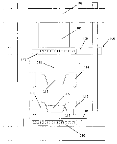
Figures 5A and 5B illustrate a cross-sectional view of an ejection mechanism
134
in accordance with embodiment of the present invention. Figure 5A is an
illustration of
ejection mechanism 134 at rest, while Figure 5B is an illustration of ejection
mechanism
134 in operation.
Referring first to Figure 5A, ejection mechanism 134 is housed in mould cavity
111 and positioned under a moulded product 136. Ejection mechanism 134
comprises a
head 138 coupled to a base 140 by a shaft 142 and a spring 144 around shaft
142. At rest,
spring 144 is in an uncompressed state.
In this embodiment, ejection mechanism 134 is operated by a pneumatic system
(not illustrated). Shaft 142 may be provided with an 0-ring 146 to prevent a
loss of air
from the pneumatic system. In an alternative embodiment, ejection mechanism
134 may
be operated by a hydraulic system
CA 02570132 2006-12-08
WO 2005/120787 PCT/SG2005/000109
When clearance C is increased or when moulded product 136 is to be removed
from mould cavity 111, the pneumatic system is activated and exerts a force on
base 140,
driving ejection mechanism 134 in a direction X as illustrated in Figure 5B
and
compressing spring 144 in the process. Accordingly, moulded product 136 is
lifted from
mould cavity 111.
Ejection mechanism 134 is returned to the position of rest illustrated in
Figure 5A
by deactivating the pneumatic system. Correspondingly, spring 144 is released
from its
compressed state. The expansion of spring 144 exerts a force on base 140,
driving
ejection mechanism 134 in an opposite direction relative to direction X until
the position
1o of rest is attained.
The pneumatic or hydraulic system may be operated with the same limit switch
that is used to reduce the speed at which mould plunger 113 approaches mould
cavity
I11.
Referring back to Figure 4, mouldable composition 116 should not be left in
mould cavity 111 for an extended period of time as then the adhesive and the
fibre
mixture may absorb too much heat and become burnt. Cracks and deformation may
also
occur if mouldable composition 116 is left in mould cavity 111 for an extended
period of
time as then too much moisture will be lost.
The degree to which mould cavity 111 is filled affects the density of the
moulded
product. If insufficient mouldable composition 116 is loaded into mould cavity
111,
there will not be enough of mouldable composition 116 to fill the space in
mould cavity
111 between first mould part 110 and second mould part 112 and there will be
insufficient pressure build-up to form porous structure 126. As such, a dense
moulded
product with high moisture content is formed when insufficient mouldable
composition
116 is loaded into mould cavity 111.
Figure 6 is a flow chart illustrating a method 150 to form a moulded product
in
accordance with another embodiment of the present invention. Method 150 begins
by
loading 152 a mould cavity of a first mould part with a mouldable composition.
The
mould cavity may be loaded 152 up to about 90 % of the capacity of the mould
cavity.
21
CA 02570132 2006-12-08
WO 2005/120787 PCT/SG2005/000109
A packing pressure of between about 435 to 870 psi is applied 154 to the
mouldable composition for between about 20 to 60 s to allow the mouldable
composition
to cure. A predetermined clearance of between about 0.1 to 0.5 mm is
maintained 156
between the first mould part and a second mould part to allow the discharge of
excess
mouldable composition, water vapour and other vapours released during the
curing of the
mouldable composition. The first mould part and the second mould part are
maintained
at a temperature of between about 110 to 180 C. The first mould part is
preferably
maintained at a temperature of about 20 C higher than a temperature of the
second
mould part to compensate for heat loss when the mouldable composition is
loaded into
the mould cavity and to prevent the first mould part and the second mould part
from
jamrning due to thermal expansion of the first mould part and the second mould
part.
The clearance between the first mould part and the second mould part is
increased
158 to about 10 mm when the mouldable composition is substantially cured,
preferably
about 90 % cured, forming the moulded product. When the water vapour and other
vapours released during the curing of the mouldable composition are
substantially
discharged, the clearance is reduced 160 to between about 0.05 to 0.3 mm for
between
about 15 to 60 s. This is done to compress the moulded product to a desired
thickness
and to iron the surface of the moulded product before removing 162 the moulded
product
from the mould cavity.
Tables 4A and 4B illustrate examples of process parameters that may be used to
form a pallet in accordance with one embodiment of the present invention.
Table 4A
Example 1 Example 2 Example 3
Percentage Volume of Mould Cavity Filled (vol %) 70 80 90
Temperature of Mould Cavity C 125 125 125
Temperature of Mould Plunger C 105 105 105
Packing Pressure ( si 870 870 870
Curing Time (s) 60 60 40
Curing Clearance (mm) 0.8 0.6 0.5
Ironing Time (s) 60 60 60
Ironing Clearance (mm) 0.5 0.3 0.1
22
CA 02570132 2006-12-08
WO 2005/120787 PCT/SG2005/000109
Table 4B
Example 4 Example 5 Example 6
Percentage Volume of Mould Cavity Filled (vol %) 85 87 92
Temperature of Mould Cavity C 125 130 130
Temperature of Mould Plunger C 105 110 110
Packing Pressure (psi) 870 870 870
Curing Time (s) 50 60 60
Curing Clearance mm 0.4 0.2 0.5
Ironing Time (s) 60 40 60
Ironin Clearance (mm) 0.1 0.05 0.2
Tables 5A and 5B illustrate examples of process parameters that may be used to
form a flowerpot in accordance with one embodiment of the present invention.
Table 5A
Example 7 Example 8 Example 9
Percentage Volume of Mould Cavity Filled (vol %) 85 87 91
Temperature of Mould Cavity C 100 100 125
Temperature of Mould Plunger C 80 80 105
Packing Pressure (psi) 435 580 725
Curing Time (s) 30 30 30
Curing Clearance (mm) 1.5 1.2 1.8
Ironing Time (s) 30 30 30
Ironing Clearance (mm) 1.0 1.0 1.0
Table 5B
Example 10 Example 11 Example 12
Percentage Volume of Mould Cavity Filled (vol %) 65 75 60
Temperature of Mould Cavity C 125 125 130
Temperature of Mould Plun er C 105 105 110
Packing Pressure (psi) 435 650 870
Curing Time (s) 30 60 60
Curing Clearance (mm) 1.2 1.0 2.0
Ironin Time (s) 30 60 15
Ironin Clearance mm 1.0 0.8 0.8
Apart from pallets, trays and flowerpots, it will be appreciated that the
invention
may be used to mould a variety of products such as, for example, partition
boards,
23
CA 02570132 2006-12-08
WO 2005/120787 PCT/SG2005/000109
ammunition containers, speaker boards, electronic casing, cups, plates, car
bumpers,
steering wheels, panel boards, car seats, chair seats and table tops.
Other embodiments of the invention will be apparent to those skilled in the
art
from consideration of the specification and practice of the invention. The
word
"comprising" and forms of the word "comprising" as used in the description and
in the
claims are not meant to exclude variants or additions to the invention.
Furthermore,
certain terminology has been used for the purposes of descriptive clarity, and
not to limit
the present invention. The embodiments and preferred features described above
should
be considered exemplary, with the invention being defined by the appended
claims.
24