Note: Descriptions are shown in the official language in which they were submitted.
CA 02570356 2008-12-22
70635-83
- 1 -
Multi-positionable wall or ceiling panel
Description
The present invention relates to a panel, which is suitable for a covering for
a wall
and / or ceiling as well as to a related method for laying the same. Such
panels
preferably comprise wood material, but they may also be made from metal
and / or plastics. Known panels for walls or ceilings are provided with a
groove
1o and a tongue coniection on their longitudinal sides, whei-eby adjacent
similar
panels may be assembled to a surface in a form-fitting and interengaging
manner.
The known panels are fastened to wall or ceiling by means of clamps or a
staple
gun. During stapling of the panels, the optical appearance, which is provided
by
the surface of the panels, is often adversely affected.
From the prior art a panel for a wall is further known onto which metallic
clamps
may be clipped for connecting the same with other panels. By means of the
clamps, the spacing between the connected panels may be varied. Due to the us-
age of additional clamps, the application of the panels is, however, time and
cost
consuming and the logistic complexity associated therewith is increased.
With regard to the above-described disadvantages, it is thus an object of
embodiments
of the present invention to provide a panel with improved connecting,
respectively
laying properties, as well as a corresponding application and related laying
method.
CA 02570356 2008-12-22
70635-83
- la -
In one aspect of the present invention, there is
provided a panel for a wall or a ceiling with coupling means and
locking means, which panel is provided on at least one side with a
decor layer, wherein the coupling means are formed such that the
panel is connectible with further similar formed panels in
multiple different positions with respect to each other and
wherein the coupling means are provided with a groove formed by
two lips on an edge of the panel, and wherein the coupling means
comprise a tongue on an opposite edge of the panel which is formed
such that it can be inserted into a further groove of an edge of a
further similar formed panel, and wherein at least one element of
the locking means is arranged at the coupling means, which locking
means are formed such that they engage with each other and that at
least two locking positions in coupling direction are possible;
wherein the coupling means consisting of groove and tongue are at
least partially covered with a decor layer.
In another aspect of the present invention, there is
provided a use of panels described herein.
In another aspect of the present invention, there is
provided a method for the laying of a wooden panel described
herein, wherein in a first step a first panel is brought into
engagement with a second panel and the panels are set in an angled
position with respect to each other, wherein in a second step at
least one of the panels, in particular the first panel, is pivoted
into a common plane and a locking of the panels is thus achieved.
In still another aspect of the present invention, there
is provided a method for production of a panel described herein,
wherein the panel is provided in a first step at least at the
longitudinal sides with rounded or cutoff edges and in a second
step the panel is provided on one side with a decor layer, and in
a third step the coupling means and/or locking means are milled
into the panel.
CA 02570356 2006-12-13
-2-
The panel according to the invention for a wall or a ceiling is provided with
cou-
pling means. The coupling means are formed such that a panel may be connected
with another panel in multiple different positions with respect to each other.
For
example positions with different distance between the longitudinal edges of
two
panels, which are arranged in parallel to each other. In this way, it can be
achieved
that the distance of the panels may be varied depending on the area to be
covered,
in particular without the need for any further tools, to influence on the one
hand
the necessary number of panels for a given area to be covered. Since
additional
tools, like e.g. clamps, are not necessary, the logistic complexity, which is
related
to storing, transport and application of the panels, is advantageously
reduced.
On the other hand, the optical appearance, which derives from the different
spac-
ing of the panels may be influenced. For example, the panels may lie close to-
gether to form a closed surface when viewed upon or the panels may show a re-
cess running between the panels in coupled condition, by means of which the
panel structure of an area covered with the panels is optically emphasized.
The
coupling means formed in this way may be provided both on the longitudinal
side
as well as on the narrow side. Further, different, i.e. conventional or even
no cou-
pling means may be provided on the narrow side.
In a further preferred embodiment of the panel according to the invention, cou-
pling means are provided with a groove formed by two lips on the one side of
the
panel and a tongue on the other side of the panel. In this case, the tongue is
formed such that it may be moved into the groove of another panel. A groove
and
tongue connection is particularly easy and cost efficient to make, e.g. by
means of
milling of the panels. Such a connection may be provided particularly easily
in a
continuous panel-manufacturing process.
According to a further advantageous embodiment, one of the two lips is longer
than the other. In this way, it is on the one hand achieved that the lip is
easily ac-
CA 02570356 2006-12-13
-3-
cessible for machining. In this way, during the manufacturing process of the
pan-
els, recesses and projections may easily be provided in the protruding lip. On
the
other hand, the protruding lip facilitates the connection of multiple panels.
For
example, the tongue of an angled panel may easily be arranged onto the protrud-
ing lip, to slide over this lip effortlessly into the corresponding groove. In
this
way, the assembly of panels is simplified. When mounting to walls and
ceilings, it
is a particular advantage to provide an insertion aid made in this way, since
it is
particularly difficult to correspondingly align the panel during this form of
mount-
ing.
In one embodiment, the projecting lip is thus on the underside of the panel,
that
means on the side of the panel, which faces to the ceiling or the wall when
cor-
rectly applied. In this way, next to the above-described advantageous effect,
the
optical impression of the installed panels is not negatively affected by the
cou-
pling elements.
In a further advantageous embodiment, at least one element of the locking
means
is arranged on the coupling means. In this way, it is achieved that the
locking
element may be provided with the panels together with the coupling means
during
the manufacturing process. If for example a lock-ing element is provided on
the
long lip of the groove, a slightly angular position of the panel with respect
to this
lip may advantageously be sufficient to disable the locking. If for example
the
connection to another panel is to be established by means of groove and
tongue,
this angled position is sufficient that the locking means are not engaged with
each
other, and the establishing of a connection is facilitated. On the other hand,
the
angular position leads to a release of the locking of connected panels, so
that two
panels may be separated from each other easily, when positioned in this
angular
arrangement.
To achieve this angled position comparatively easily, in one embodiment the
cou-
pling means may be provided overall or in contacting areas in an elastic
configu-
CA 02570356 2006-12-13
-4-
ration. In one embodiment, the recesses as well as the projecting lip are
arranged
on the underside of the panel, i.e. on the side of the panel, which faces the
wall or
the ceiling, when the panel is correctly applied. In this way, the optical
impression
of the installed panels is not negatively influenced by the locking means.
A further advantageous embodiment of the panel according to the invention pro-
vides that the locking means are shaped such that they engage each other. In
this
way, a locking is provided in a particularly simple manner, which may also be
released easily.
In a further advantageous embodiment, the locking means comprise one or more
recesses and projections respectively lugs. For example, in one embodiment,
two
recesses and one projection are provided. The projection has a cross-section
which
allows it to engage one of the recesses.
To facilitate the insertion of the projection into the recess, the projection
may be
more angled on the one side, which is arranged ahead in the connection
direction,
compared to the opposite side. The opposite side should be angled in such a
way
that in combination with the respective recess, a sufficiently strong locking
is
achieved.
In a further embodiment, the locking means could further be provided
elastically,
to facilitate the locking.
A further preferred embodiment provides that the locking means are arranged
con-
tinuously along the longitudinal sides of the panel. For example, one or more
re-
cesses could be provided on the longitudinal side of a panel, in the fozm of a
groove. In this way, the same can e.g. be machined into the panels by means of
a
milling action. Therefore, such a panel can be produced in a particularly
simple
manner by means of a continuous production process. On the other hand, due to
the relatively large locking surface, a particularly effective locking is
achieved.
CA 02570356 2006-12-13
-5-
For example, the projection and the corresponding recess could be relatively
small
in cross-section and nevertheless a sufficiently strong locking may be
achieved
due to the extending shape of projection and recess along the panel.
Projections
and recesses with a small cross-section are particularly advantageous with
thin
panels.
According to a further embodiment, the locking means are provided with a
plural-
ity of elements spaced in the connecting direction of the panels. For example,
the
elements could be two recesses, arranged in parallel along the panel and being
offset with respect to each other. In one embodiment, they are provided on the
side of the panel, which is provided with the tongue. A projection, arranged
along
the panel, which is provided on the projecting groove-fonning lip can alterna-
tively be locked in these recesses. By means of the offset elements, it can
particu-
larly easily be achieved that the distance of the panels may be varied
depending
on the surface to be covered, in order to influence the necessary number of
panels
for a given surface to be covered. Further, the optical 'unpression which
derives
from the different spacing of the panels may be changed. For example, the
panels
could be arranged close to each other, by locking the projection in one embodi-
ment into the recess, which is distant to the longitudinal edge. In this way,
a rela-
tively closed surface is achieved. Alternatively, the panels may be connected
spaced apart from each other, compared to the above-described arrangement, and
may be provided with a recess between panels, when the projection is locked
into
the recess, which is directly adjacent to the longitudinal edge. In this way,
a panel
structure of a surface covered with the panels is optically emphasized.
According to a further embodiment, the coupling means and / or locking means
are shaped such that the panels are slidable against each other in
longitudinal di-
rection when in connected condition.
In one embodiment, they are for example shaped such that the panels may be
moved in a rail-like manner against each other. In this way, it is achieved
that
CA 02570356 2006-12-13
-6-
with connected panels an extension or shortening of the length does e.g. in
the
case of wooden panels not lead to a warping or even damaging of the panels.
In a further embodiment, the coupling means and / or the locking means are
shaped such that the same are provided with a play in at least one direction.
In this
way, the movability may be secured respectively the necessary forces for the
same
may be reduced. Further, shrinkage as well as expansions may be balanced. A
play between the groove and the tongue allows that the above-described angled
position of two panels with respect to each other can be achieved particularly
simply. The play may be equal between the groove and the tongue, or alterna-
tively the groove may be widened in the insertion direction. A play between
the
locking means serves to balance expansions and shrinkage of the panels. A play
at
the free end of the protruding lip of the groove serves in one embodiment for
the
fastening of a clamp, by means of which the panel may be fastened to wall or
ceil-
ing. By providing clamps for the fastening of the panel, the same can be
fixed, e.g.
by means of nailing, stapling or a screw connection without damages to the sur-
face of the panel. Further, the panel need not be provided with additional
milled
recesses, to fix the clamps.
In a further embodiment, the panel consists of a wooden fiberboard. Thus, on
the
one hand, the panel is relatively inexpensive to produce. On the other hand,
it is
comparatively very resistant to deformation, very stress resistant and can be
pro-
duced with a high precision. The panel can be produced in one piece from a
fiber-
board.
A further preferred embodiment provides that the panel is provided at least on
one
side with rounded edges or cutoff edges. Cutoff edges in the meaning of the in-
vention can, e.g. be achieved by providing rectangular or square edges, with
one
or more leveled faces by means of milling. In this way, the risk of injury is
re-
duced.
CA 02570356 2006-12-13
-7-
In one embodiment, the edges, which border the top side of the panel are
rounded
or cutoff, i.e. on the side of the panel which is arranged remote from the
wall or
the ceiling, when correctly applied. In particular with wall panels the risk
of injury
for humans and the risk for damaging of clothing can be reduced by providing
the
above-described feature in a particularly advantages manner. Further, it is
achieved that small differences in the arrangement of the topside of the
panels,
which might e.g. be caused by tolerances in the production, do not stand out,
since
the topsides of the panels do not directly merge into each other, but they are
di-
vided by the rounded, respectively cutoff edges. In this way, the
manufacturing
process is simplified since e.g. tolerances with regard to the milling action
are
reduced.
In a further preferred embodiment, the panels are provided on at least one
side
with a d6cor layer. For example, this could be a decor paper, which is
provided
with a wood grain. The decor paper can have different colorings and / or struc-
tures according to the desired optical effect. In addition to the optical
effect, it
may function as protection of the panel against moisture. Further, it can be
achieved that a painting of the panels with regard to optical or protective
aspects
can advantageously be avoided after application onto a wall or ceiling.
In one embodiment, the decor layer is only provided essentially on the top
side of
the panel, thus on that side of the panel which is arranged distant to the
wall or
ceiling, when correctly applied.
According to a further embodiment, the coupling means are at least partly
covered
by a decor layer. In this way, it can be achieved that the ddcor layer is
additionally
fixed by means of the coupling means. A release of the usually glued-on decor
layer can thus further be avoided. The sliding or gliding properties of the
decor
layer are preferably improved compared to the abutting surfaces of wood materi-
als, since this has a positive effect on the slidability in longitudinal
direction of the
connected panels.
CA 02570356 2006-12-13
-8-
The panel according to the invention according to any one of the above
described
embodiments is advantageously iised as a covering for walls and / or ceilings.
The laying method according to the invention provides that in a first step a
first
panel is brought into engagement with a second panel, and whereby the panels
are
arranged in an angled position with respect to each other. In a second step,
at least
one of the panels, in particular the first panel, is pivoted in a common
plane, thus
establishing a locking between the panels. By means of the achieved locking,
the
lo panels can be advantageously simply connected. For example, the first panel
may
be provided with a groove, formed from two lips, into which the tongue of the
second panel may be inserted. One of the lips projects for example. In this
way,
the tongue of the angled panel is arranged onto the projecting lip, so that
the same
can be brought into the respective groove by means of a sliding operation in a
particularly simple manner. In the angled position, the locking means of the
pan-
els are not engaged and do thus not hinder the establishing of the connection.
By
pivoting the panels into one plane, the locking means engage, and lock e.g.
into
place and thus secure the connection of the panels.
The invention further relates to a manufacturing method for a panel, according
to
any one of the above described embodiments, wherein the panel is in a first
step
provided at least on the longitudinal sides with rounded or cut-off edges, in
a sec-
ond step the panel is provided on one side with a d6cor layer and in a third
step,
the coupling means and / or locking means are milled into the panel. Thereby,
the
panel can be produced in a simple and cost efficient manner into one of the
above
described embodiments.
In a further preferred embodiment, the panel rests in the third step on the
side,
which is not provided with a d6cor layer. For example, the panel rests on a
surface
of the milling machine. In this way, it is achieved that the comparably
delicate
d6cor layer is not damaged during the machining.
CA 02570356 2006-12-13
-9-
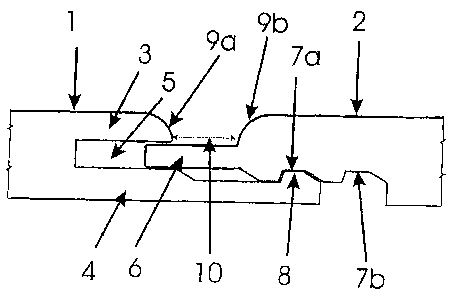
With regard to the figures:
Fig. 1 shows two panels 1, 2 in cross-section, which are connected in a first
posi-
tion. The panel 1 is provided with two lips 3, 4, by means of which the groove
5
arranged there-between is formed. The tongue 6 of the second panel 2 can be
brought into the groove S. Groove 5 and tongue 6 form the coupling means of
panels 1, 2. The lip 4 of the panel I projects further than the lip 3. A
projection 8
is provided on the outer edge of the panel 1, respectively the lip 4, which
extends
along the panel 1. The projection 8 can be locked in one of the two recesses
7a,
respectively 7b. The same form the locking means of the panels 1, 2. The
recesses
7a, 7b extend along the longitudinal edge of panel 2 and are arranged parallel
with
respect to each other. The recess 7a is arranged in close relationship to the
edge of
panel 2, whereas the recess 7b is arranged fiuther away with respect to the
edge of
panel 2. In fig. 1, it is shown how projection 8 engages in the recess 7a,
which is
next to the edge of panel 2, and thus locks panels 1, 2 with each other. In
this way,
panels 1, 2 can be locked within a distance from each other and the surface
cov-
ered by panels 1, 2 is enlarged. A recess 10 is formed between the edges 9a
and
9b, wherein the distance between the edges is for example 7.5 mm. The recess
10
2o extends along the panels 1, 2 and contributes to the optical effect of the
same.
Edges 9a and 9b are rounded. In fig. 1, the lower sides of panels 1 and 2 are
those
sides which abut the wall respectively the ceiling after application onto a
wall or
ceiling.
Fig. 2 shows the two panels 1, 2 of fig. 1 in a cut view, which panels are con-
nected in a second position. Panel I is provided with two lips 3, 4, by means
of
which a groove 5 is formed there-between. Tongue 6 of the second panel 2 may
be inserted into groove 5. Groove 5 and tongue 6 form the coupling means of
pan-
els 1, 2. Lip 4 of panel I projects further than lip 3. A projection 8 is
provided on
the outer edge of panel 1, respectively the lip 4, which extends along panel
1. Pro-
jection 8 can be locked in any one of the recesses 7a, respectively 7b. The
same
CA 02570356 2006-12-13
-10-
form the locking elements of panels 1, 2. The recesses 7a, 7b extend along the
longitudinal edge of panel 2, and are arranged in parallel to each other. The
recess
7a is in close relationship to the edge of panel 2, whereas the recess 7b is
arranged
further away froxn the edge of panel 2. In fig. 2, it is shown how projection
8 en-
gages into recess 7b, which is arranged distant to the edge of panel 2, and
locks
the panels 1, 2 with each other. In this way, panels 1, 2 are locked close
with re-
spect to each other and the surface covered by panels 1, 2 is comparably
small.
Between the directly adjacent edges 9a and 9b, a recess 10' is formed. The
recess
10' runs along the panels 1, 2 and contributes to the optical effect of the
same.
The edges 9a and 9b are rounded. In fig. 2, again the lower sides of panels 1
and 2
are those sides which abut the wall respectively ceiling after application
onto a
wall or ceiling.
Fig. 3 is a detailed view of fig. 1. Projection 8 of lip 4 is engaged in
recess 7a and
thus locks two panels with each other. The cross-section of projection 8 is
formed
such that it can engage the recess 7a. To facilitate the projection 8 into
recess 7a,
the projection 8 provided on the side 12' which is in connecting direction ar-
ranged ahead, is more angled compared to the opposite side 11'. The same is
true
for the corresponding sides 11 respectively 12 of recess 7a. Sides 11
respectively
11' are angled in such a way that on the one hand they provide in combination
with the recess a sufficiently strong locking and on the other hand allow an
easy
angling of the panels with respect to each other, such that the locking by
means of
elements 7a, respectively 8, can be released in a simple manner. The locking
ele-
ments 7a, 8 in this embodiment are provided with play, to allow a displacement
of
the panels with respect to each other. 'The play should e.g. be from 0.2 mm to
0.5
mm.
Fig. 4 shows two panels 1', 2' according to a further embodiment of the
invention
in a sectional view, which panels are connectable in two positions, of which
one is
shown. Panel 1' is provided with two lips, by means of which a groove is
formed
there-between. The tongue of the second panel 2' can be inserted into the
groove.
CA 02570356 2006-12-13
-11-
Groove and tongue form the coupling means of panels 1', 2'. The lip 4' of
panel
1' projects further than the other lip. A projection 8' is provided on the
outer edge
of panel 1' respectively of the lip 4', which projection runs along panel 1.
Projec-
tion 8' can be engaged in one of the recesses 7, 8', 7b', respectively of
panel 2'. In
the embodiment shown, it is engaged in recess 7, 8. The same form the locking
means of panels I', 2'. The recesses 7a', 7b' extend along the longitudinal
edge of
panel 2' and are arranged in parallel with respect to each other. Recess 7a'
is ar-
ranged in close relationship to the edge of panel 2', whereas recess 7b' is
arranged
further distant to the edge of panel 2'. Once projection 8' is engaged in the
recess
l0 7a', respectively 7b', a play 20 remains. This play 20 serves among others
for the
reception of the clamp 22, which is shown in fig. 5 in a detailed view. This
clamp
22 allows a simplified fastening of wall panel 1' and thus also of panel 2'
onto a
wall or ceiling. To prevent that play 20 leads to a loose locking in the
direction of
the groove and tongue connection, the locking means are further provided with
an
ls additional projection 21 at the lip 4' of panel 1', which lock with a
protruding
projection 23 of panel 2'.