Note: Descriptions are shown in the official language in which they were submitted.
CA 02570777 2006-12-11
INTERNALLY MOUNTED DEVICE FOR A GAS TURBINE ENGINE
TECHNICAL FIELD
The invention relates generally to combustors for gas turbine engines and,
more
particularly, to improved devices mounted in such combustors.
BACKGROUND OF THE ART
Gas turbine engines usually include a combustor assembly having a casing
receiving compressed air from the compressor section, and into which several
devices
project, for example fuel nozzles, ignitors, etc. Generally, a plurality of
holes are provided
in the casing through which such devices extend, with the casing usually being
reinforced
in the portion around the holes by flanged areas or bosses. The devices, e.g.
fuel nozzles,
typically include an extending flange which mates with the reinforced portion
around the
respective hole on the exterior surface of the combustor casing. The
reinforced portion
and flange may further include additional aligned threaded holes which receive
fasteners,
such as bolts, to retain the flange to the casing and ensure an adequate seal
between the
devices and the casing through which they project. The flange and reinforced
portion must
be thick enough not to distort under the high temperature and pressures to
which they are
exposed, since the compressed air within the casing will produce a force which
acts to
separate the flange from the reinforced portion in an attempt to force the
device out
through the corresponding hole in the casing. Such an "exterior" mounting of
the device
on the combustor casing requires relatively complex and heavy fastening and
sealing
means, however is commonly used because of the ease with which such devices
can be
removed from the outside of the casing if required, for maintenance purposes
for example.
Accordingly, there is a need to provide an improved device mounted within a
combustor assembly.
SUMMARY OF THE INVENTION
It is therefore an object of this invention to provide an improved device
mounted
within a pressure vessel casing.
CA 02570777 2006-12-11
2
In one aspect, the present invention provides an assembly comprising: a casing
having a casing wall defining an enclosure, the casing wall having an inner
wall surface
located within the enclosure, the enclosure being adapted to contain
pressurized fluid, the
casing including at least one hole define therethrough, at least one device,
the device
including an outer end located outside of the enclosure, an inner end located
inside of the
enclosure, and a stem connecting the outer and inner ends, the stem passing
through the
hole, the stem including first means for transferring a load produced by a
pressure of the
pressurized fluid to the casing by one of direct contact with the inner
surface and contact
with the inner surface through a sealing element, the first means sealing the
hole when the
load is transferred and preventing the stem from being removed from the hole
in an
outward direction defined along an axis of the stem toward the outside of the
enclosure,
and second means engaged with the device and the casing for retaining the stem
in place
within the hole and preventing movement of the stem in an inward direction
defined along
the axis of the stem toward the inside of the enclosure, the second means
being
substantially free of the load transferred by the first means, the second
means being
disengageable from at least one of the device and the casing to remove the
stem from the
hole in the inward direction.
In another aspect, the present invention provides an assembly comprising: a
pressure vessel casing adapted to contain at least pressurized fluid, the
pressure vessel
casing having a wall defined by annular inner and outer surfaces with at least
one hole
defined therethrough, at least one device including an inner end and an outer
end
interconnected by an elongated stem, the stem being located within the hole,
the inner and
outer ends being respectively located inside and outside of the casing, the
stem including
a flange extending outwardly therefrom across a distance greater than a
diameter of the
hole and being disposed inside the casing adjacent to the inner surface, a
portion of the
inner surface aligned with the flange encompassing a border region of the
hole, the flange
preventing the stem to be removed from the hole in an outward direction
defined along an
axis of the stem toward the outside of the casing, a sealing element located
between the
stem of the device and the casing, the flange pressed against the inner
surface by the
pressurized fluid cooperating with the sealing element to seal the hole, and a
removable
retaining element retaining the device to the casing against movement in an
inward
CA 02570777 2006-12-11
3
direction defined opposite of the outward direction, the stem of the device
being
disengeagable from the casing through the hole in the inward direction upon
removal of
the retaining element.
In a further aspect, the present invention provides a fuel nozzle assembly
adapted
to be received in a hole of a combustor casing in a gas turbine engine, the
assembly
comprising: a manifold interface and a nozzle tip interconnected by a stem,
the stem being
smaller than the hole and providing fluid communication between the manifold
interface
and the nozzle tip, the manifold interface being at least one of smaller than
the hole and
detachable from the stem, a flange extending outwardly from the stem relative
to a
longitudinal axis thereof, the flange being larger than the hole such as to
prevent the stem
from passing therethrough, and a retaining element removably engaging the stem
between
the manifold interface and the flange, the retaining element extending
outwardly from the
stem relative to the longitudinal axis, the retaining element being larger
than the hole such
as to prevent the stem from passing therethrough.
Further details of these and other aspects of the present invention will be
apparent from the detailed description and figures included below.
DESCRIPTION OF THE DRAWINGS
Reference is now made to the accompanying figures depicting aspects of the
present invention, in which:
Fig. 1 is a schematic side view of a gas turbine engine;
Fig. 2 is a schematic side view of a mounting of a fuel nozzle in a combustor
according to an aspect of the present invention;
Fig. 3 is a schematic partial side view of a mounting for a device in a
pressure
vessel according to an alternative aspect of the present invention;
Fig. 4 is a schematic partial side view of a mounting for a device in a
pressure
vessel according to another alternative aspect of the present invention; and
Fig. 5 is a schematic partial side view of a mounting for a device in a
pressure
vessel according to a further aspect of the present invention.
CA 02570777 2006-12-11
4
DETAILED DESCRIPTION OF THE PREFERRED EMBODIMENTS
Fig. 1 illustrates a gas turbine engine 10 of a type preferably provided for
use in
subsonic flight, generally comprising in serial flow communication a fan 12
through
which ambient air is propelled, a multistage compressor 14 for pressurizing
the air, a
combustor 16 in which the compressed air is mixed with fuel and ignited for
generating
an annular stream of hot combustion gases, and a turbine section 18 for
extracting energy
from the combustion gases.
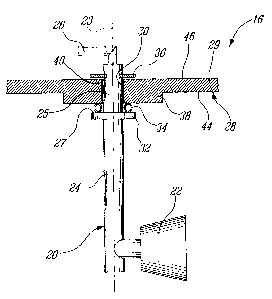
Referring to Fig. 2, the combustor 16 includes a casing 28 having a liner
wa1129
defined by an outer surface 46 and an inner surface 44, the inner surface 44
defining an
enclosure receiving compressed air from the compressor 14 (see Fig.1).
Although the
combustor 16 is shown in Fig. 1 as being part of a turbofan engine 10, it is
understood
that the combustor 16 can be part of various other types of gas turbine
engines, for
example a turboprop engine or a stationary industrial gas turbine engine.
The casing 28 includes at least one array of circumferentially spaced apart
holes
30 defined through the wa1129, only one of which is shown, with each hole 30
receiving a
device 20 therein. The casing wall 29 preferably includes a reinforced portion
38 of
increased thickness around each hole 30; although if the thickness of the
casing wa1129 is
sufficient such a reinforced portion 38 can be omitted. Further, although some
additional
support is provided by the reinforced portion 38, as no threaded fasteners are
required for
securing the device 20 to the casing 28, this reinforced portion 38 need not
nearly be as
thick as those of the prior art through which threaded holes for fastening
bolts therein are
required.
The device 20 received within the hole 30 is preferably a fuel nozzle, which
includes an inner end or nozzle tip 22, an outer end or manifold interface 26
for
connecting the fuel nozzle 20 to a fuel manifold (not shown), and a body
portion or stem
24 connecting the nozzle tip 22 to the manifold interface 26. The stem 24
includes an
outer portion 25 adjacent the manifold interface 26 and the hole 30 is sized
such that at
least this outer portion 25 can be inserted therethrough, with the nozzle tip
22 being
located inside the casing 28, the manifold interface 26 being located outside
the casing 28,
and a longitudinal axis 23 of the stem 24 preferably passing through the
center of the hole
CA 02570777 2006-12-11
30. The hole 30 is also preferably sized such that the manifold interface 26
can pass
therethrough. Alternatively, the manifold interface 26 can be detachable from
the outer
portion 25 of stem 24 such as to remain outside of the casing 28 when the fuel
nozzle 20
is removed from the inside of the casing 28, in which case the hole 30 need
only be
5 sufficiently large to closely fit the outer stem portion 25 therein.
Although the device described herein is the fuel nozzle 20, it is understood
that
the device can be of another type, including but not limited to, an ignitor, a
support
member, etc.
The stem 24 includes a flange 32, preferably circular, extending outwardly
from
the stem 24 relative to the axis 23, located inside the casing 28 and having
an outer
surface 27 adjacent the inner surface 44 of the casing wa1129. The flange 32
is sized to be
larger than the hole 30, so that the portion of the inner surface 44 which is
aligned with
the flange 32 includes a border region of the inner surface 44 surrounding the
hole 30.
Accordingly, the flange 32 requires the fuel nozzle 20 to be inserted in the
hole 30 from
the inner side of the casing wall 29. The flange 32 is preferably separated
from the inner
surface 44 by a sealing element 34, which in one embodiment includes an
annular sealing
ring with a C-shaped cross-section. The flange 32, being larger than the hole
30, and
disposed on an inner side of the casing wall 29, prevents the stem 24 from
sliding out of
the hole 30 in an outward direction, i.e. along the axis 23 of the stem 24
toward the
outside of the casing 28The stem 24 includes an annular groove 40 spaced apart
from the
flange 32 in a direction away from the nozzle tip 22 such as to be located
outside of the
casing 28, adjacent the outer surface 46 when the stem 24 is inserted into the
hole 30 with
the outer surface 27 of the flange 32 adjacent the inner surface 44 of the
casing wa1129. A
retaining element, such as a retaining clip 36, engages the annular groove 40.
The
retaining clip 36 is sized to be larger than the hole 30 to abut a border
region of the outer
surface 46 which surrounds the hole 30, thus preventing the stem 24 from
moving in an
inward direction, i.e. along the axis 23 of the stem 24 toward the inside of
the casing 28.
The retaining clip 36 can be removed to permit the movement in the inward
direction of
the stem 24 allowing the nozzle 20 to be disengaged from the hole 30.
CA 02570777 2006-12-11
6
Alternative retaining means for the retaining clip 36 include, for example, a
nut
threaded around a threaded portion of the stem 24, a pin inserted in a hole
extending
transversely through the stem 24, etc.
In use, the sealing element 34 is placed around the stem 24 against the outer
surface 27 of the flange 32, and the fuel nozzle 20 is inserted into the hole
30. This is
done from the inside of the casing 28, i.e. by passing the manifold interface
26, then the
outer portion 25 of the stem 24, through the hole 30 in the outward direction
until the
annular groove 40 is located outside of the casing 28. The outward motion is
stopped by
contact of the sealing element 34, pressed by the flange 32, with the inner
surface 44 at
the periphery of the hole 30. The retaining clip 36 is engaged with the groove
40 in the
stem 24 to prevent the nozzle 20 from sliding out of the hole 30 in the inward
direction.
When the combustor 16 is used, the pressurized fluid, in this case air, within
the
casing 28 acts to push the flange 32 against the inner surface 44, compressing
the sealing
element 34 and thus sealing the hole 30. The load produced by the pressurized
air is
transferred directly from the flange 32 to the casing 28 through the sealing
element 34,
with the retaining clip 36 being free substantially of that pressure-induced
load. As such,
the retaining clip 36 can be relatively small and lightweight.
When the fuel nozzle 20 needs to be removed, the retaining clip 36 is
disengaged
from the nozzle groove 40, and the stem 24 is free to slide in the inward
direction to
remove the fuel nozzle 20 from the inside of the casing 28.
Referring to Fig. 3, an alternative mounting of a device 120 in a pressure
vessel
casing such as a combustor casing 128 is shown. A plurality of holes 130 are
defined
through a wall 129 of the casing 128, only one of which is shown, with the
casing wall
129 also preferably including a reinforced portion 138 of increased thickness
around each
hole 130. Each hole 130 also includes, within the wall 129 of the casing 128,
an annular
groove 142, which is preferably defined at mid-distance between inner and
outer surfaces
144,146 of the casing wall 129. The device 120, which can be for example a
fuel nozzle,
has a stem 124 (only part of which is shown) having an outer portion 125
inserted into the
hole 130, the stem 124 interconnecting an inner end (not shown) located inside
the casing
CA 02570777 2006-12-11
7
128 and an outer end (not shown) located outside of the casing 128. The hole
130 is also
preferably sized such that the outer end can pass through.
The stem 124 includes a flange 132 extending outward therefrom relative to a
central stem axis 123, located inside the casing 128 and adjacent the inner
surface 144.
The flange 132 includes at its outer periphery a flexible integral sealing
element 134,
which abuts the inner surface 144 in a border region surrounding the hole 130.
The flange
132, larger than the hole 130, prevents the stem 124 from sliding out of the
hole 130 in an
outward direction, i.e. along the axis 123 of the stem 124 toward the outside
of the casing
128. The pressurized fluid within the casing 128 pushes the sealing element
134 of the
flange 132 against the inner surface 144, where it is deflected and seals the
hole 130. The
load produced by the pressurized fluid is transferred directly from the flange
132 to the
casing 128 through the sealing element 134.
The outer portion 125 of the stem 124 includes an annular groove 140 located
such that when the outer portion 125 is placed inside the hole 130, the
annular groove 140
is in alignment with the annular groove 142 defined in the casing 128. A
retaining clip
136 engages the aligned annular grooves 140,142. The retaining clip 136
prevents the
stem 124 from sliding with respect to the casing 128, particularly in an
inward direction,
i.e. along the axis 123 of the stem 124 toward the inside of the casing 128.
The retaining
clip 136 can be removed such as to permit the movement in the inward direction
of the
stem 124 to disengage the device 120 from the hole 130.
Referring to Fig. 4, another alternative mounting of a device 220 in a
pressure
vessel casing such as a combustor casing 228 is shown. A plurality of holes
230 are
defined through a wall 229 of the casing 228, only one of which is shown, with
the casing
wall 229 also preferably including a reinforced portion 238 of increased
thickness around
each hole 230. At the periphery of each hole 230, an annular groove 242 is
defined in an
inner surface 244 of the wall 229. The device 220, which can be for example a
fuel
nozzle, has a stem 224 (only part of which is shown) having an outer portion
225 inserted
into the hole 230, the stem 224 interconnecting an inner end (not shown)
located inside
the casing 228 and an outer end (not shown) located outside of the casing 228.
The hole
230 is also preferably sized such that the outer end can pass through.
CA 02570777 2006-12-11
8
The stem 224 includes a flange 232 extending outward therefrom relative to a
central stem axis 223, located inside the casing 228 and adjacent the inner
surface 244.
The flange 232 includes at its outer periphery a border 248, extending toward
and abutting
a border region of the inner surface 244 of the wall 229 surrounding the hole
230. The
raised border 248 creates an annular cavity 250 between the flange 232 and the
inner
surface 244 which is in fluid communication with the annular groove 242. An
annular
sealing element 234, preferably having a C-shaped cross-section, is pressed
between an
annular outer surface 231 of the outer stem portion 225 and the wall 229 of
the casing 228
within the groove 242. The flange 232, larger than the hole 230, prevents the
stem 224
from sliding out of the hole 230 in an outward direction, i.e. along the axis
223 of the
stem 224 toward the outside of the casing 228. The pressurized fluid within
the casing
228 pushes the flange 232 against the inner surface 244, thus sealing the hole
230. The
load produced by the pressurized fluid is transferred directly from the flange
232 to the
casing 228 through the border 248.
The stem 224 includes an annular groove 240 spaced apart from the flange 232
in
a direction away from the inner end such as to be located outside of the
casing 228,
adjacent the outer surface 246 of the casing wall 229 when the stem 224 is
inserted into
the hole 230 with the flange 232 adjacent the inner surface 244 of the casing
wa11229. A
retaining clip 236 engages the annular groove 240 and abuts a border region of
the outer
surface 246 which surrounds the hole 230, thus preventing the stem 224 from
moving in
an inward direction, i.e. along the axis 223 of the stem 224 toward the inside
of the casing
228. The retaining clip 236 can be removed such as to permit the inward
movement of the
stem 224 to disengage the device 220 from the hole 230.
Referring to Fig. 5, a further alternative mounting of a device 320 in a
pressure
vessel casing, such as a combustor casing 328, is shown. A plurality of holes
330 are
defined through a wall 329 of the casing 328 (only one of which is shown),
with the
casing wall 329 also preferably including a reinforced portion 338 of
increased thickness
around each hole 330. The device 320, which can be for example a fuel nozzle,
has a stem
324 (only part of which is shown) having an outer portion 325 inserted into
the hole 330,
the stem 324 interconnecting an inner end (not shown) located inside the
casing 328 and
CA 02570777 2006-12-11
9
an outer end (not shown) located outside of the casing 328. The hole 330 is
also
preferably sized such that the outer end of the stem 324 can pass
therethrough.
The stem 324 includes a flange 332 extending outward therefrom relative to a
central outer stem portion axis 323, located inside the casing 328 and
adjacent the inner
surface 344 of the casing 328. The flange 332 includes at its outer periphery
a border 348,
extending toward and abutting a border region of the inner surface 344 of the
wall 329
surrounding the hole 330. The raised border 348 creates an annular cavity 350
between
the flange 332 and the inner surface 344. An annular sealing element 334,
preferably a
seal having a U-shaped cross-section, is located in the annular cavity 350 and
pressed
between the outer surface 327 of the flange 332 and the inner surface 344 of
the casing
328. The flange 332, larger than the hole 330, prevents the stem 324 from
sliding out of
the hole 330 in an outward direction, i.e. along the axis 323 of the stem 324
toward the
outside of the casing 328. The pressurized fluid within the casing 328 pushes
the flange
332 against the inner surface 344, thus sealing the hole 330. The load
produced by the
pressurized fluid is transferred directly from the flange 332 to the casing
328 through the
border 348.
The stem 324 includes an annular threaded portion 352 spaced apart from the
flange 332 in a direction away from the inner end such as to be located
outside of the
casing 328, adjacent the outer surface 346 of the casing wall 329 when the
stem 324 is
inserted into the hole 330 with the flange 332 adjacent the inner surface 344
of the casing
wall 329. A cap washer 354 is inserted around the stem 324 and abuts a border
region of
the outer surface 346 which surrounds the hole 330. A nut 356 threadingly
engages the
annular threaded portion 352 and abuts the cap washer 354, thus preventing the
stem 324
from moving in an inward direction, i.e. along the axis 323 toward the inside
of the casing
328. The nut 356 and washer 354 can be removed such as to permit the inward
movement
of the stem 324 to disengage the device 320 from the hole 330. Optionally, a
ball tack 358
is received in a corresponding groove 360 in the outer surface 331 of the stem
outer
portion 325 to abut the casing wall 329 within the hole 330. The ball tack 358
facilitates
the installation of the stem 324 within the hole 330 by forcing the stem 324
to be inserted
with the proper orientation.
CA 02570777 2006-12-11
All of the above described embodiments can be applied to the mounting of
similar devices 20,120,220,320 in pressure vessel casings 28,128,228,328 other
than
combustor casings, such as, for example, bypass ducts in the compressor region
of a gas
turbine engine, or in any appropriate non-gas turbine applications where a
vessel contains
5 pressurized fluid.
The "interior" mounting of the device 20,120,220,320 to the casing
28,128,228,328 as herein described is particularly useful in cases where the
frequency
removal of the device is reduced to intervals corresponding to general engine
overhaul
periods.
10 When compared to an "exterior" mounting typical of the prior art, the
"interior"
mounting described herein presents several advantages. In an "exterior"
mounting, the
pressurized air tends to separate the flange from the casing, and as such the
retaining
means need to counteract that effect, producing increased loads and potential
distortions
on the flange and casing. In contrast, in the "interior" mounting of the
present invention
such increased loads are not produced in the flange 32,132,232,332 and
reinforced
portions 38,138,238,338 of the casing 28,128,228,328 since the pressurized air
tends to
press the flange 32,132,232,332 and reinforced portions 38,138,238,338
together. As
such, the flange 32,132,232,332 and reinforced portions 38,138,238,338 can
have a
reduced thickness, which leads to lighter and less costly devices
20,120,220,320 and
casings 28,128,228,328. Also, a smaller flange 32,132,232,332 reduces the
flange mass,
which in turns reduces the heat transfer from the hot inner surface
44,144,244,344 to the
device 20,120,220,320 though the flange 32,132,232,332. Because the
pressurized air
tends to press the flange 32,132,232,332 and reinforced portions
38,138,238,338 together,
the air pressure improves the seal of the holes 30,130,230,330. Thus, the
pressure
differential across the casing 28,128,228,328 improves the seal between the
device
20,120,220,320 and the casing wall 29,129,229,329, and dispenses with the need
for
complex and strong fasteners the prior art used to act against the pressure
differential in
order to maintain an adequate seal. The hole 30,130,230,330, which, contrary
to the
"exterior" mounting, does not have to be larger than the nozzle tip 22 or
device inner end,
can thus be smaller, which reduces the risks of leakage.
CA 02570777 2006-12-11
11
The above description is meant to be exemplary only, and one skilled in the
art
will recognize that changes may be made to the embodiments described without
department from the scope of the invention disclosed. For example, elements of
two or
more embodiments can be combined to produce another configuration for the
mounting of
devices 20,120,220,320 within the casing 28,128,228,328. Still other
modifications
which fall within the scope of the present invention will be apparent to those
skilled in the
art, in light of a review of this disclosure, and such modifications are
intended to fall
within the appended claims.