Language selection

Search

Patent 2570939 Summary

Third-party information liability

Some of the information on this Web page has been provided by external sources. The Government of Canada is not responsible for the accuracy, reliability or currency of the information supplied by external sources. Users wishing to rely upon this information should consult directly with the source of the information. Content provided by external sources is not subject to official languages, privacy and accessibility requirements.

Claims and Abstract availability

Any discrepancies in the text and image of the Claims and Abstract are due to differing posting times. Text of the Claims and Abstract are posted:

  • At the time the application is open to public inspection;
  • At the time of issue of the patent (grant).
(12) Patent: (11) CA 2570939
(54) English Title: IMAGE ALIGNMENT SYSTEM FOR USE IN LASER ABLATION TREATMENT OF THE CORNEA AND ASSOCIATED METHODS
(54) French Title: SYSTEME D'ALIGNEMENT D'IMAGES POUR UTILISATION DANS UN TRAITEMENT LASER COMPRENANT L'ABLATION DE CORNEE ET METHODES CONNEXES
Status: Granted and Issued
Bibliographic Data
(51) International Patent Classification (IPC):
  • A61B 03/10 (2006.01)
  • A61F 09/008 (2006.01)
(72) Inventors :
  • LEBLANC, RICHARD A. (United States of America)
  • ELDEEB, HESHAM O. (United States of America)
(73) Owners :
  • ALCON INC.
(71) Applicants :
  • ALCON INC. (United States of America)
(74) Agent: KIRBY EADES GALE BAKER
(74) Associate agent:
(45) Issued: 2015-09-08
(22) Filed Date: 2006-12-12
(41) Open to Public Inspection: 2007-06-22
Examination requested: 2011-11-02
Availability of licence: N/A
Dedicated to the Public: N/A
(25) Language of filing: English

Patent Cooperation Treaty (PCT): No

(30) Application Priority Data:
Application No. Country/Territory Date
11/315,578 (United States of America) 2005-12-22

Abstracts

English Abstract

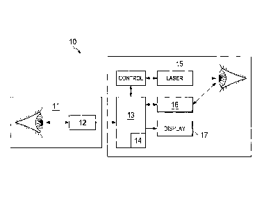
A system and method for aligning a first and a second image of an eye includes making a determination of a limbus location on a first eye image and a second eye image. The limbus location of the first and the second eye images are then aligned in two dimensions. A second eye feature location is determined on the first and the second eye image. One of the first and the second eye image is relatively rotated, and a correlation is performed on the first and the second eye image at a plurality of relative rotational positions using the second eye feature location. From the correlation an optimal first and second image alignment is identified.


French Abstract

Un système et une méthode d'alignement d'une première et d'une deuxième images d'un il comprennent la détermination de l'emplacement d'un limbe sur une première image d'il et une deuxième image d'il. Les emplacements du limbe sur la première et la deuxième image d'il sont ensuite alignés en deux dimensions. Un deuxième emplacement de caractéristique de l'il est déterminé sur la première et la deuxième images d'il. Une de la première et de la deuxième images d'il est pivotée de manière relative, et une corrélation est exécutée sur la première et la deuxième images de l'il à une pluralité de positions rotatives à l'aide de l'emplacement de la deuxième caractéristique de l'il. À partir de la corrélation, un alignement de la première et de la deuxième images est établi.

Claims

Note: Claims are shown in the official language in which they were submitted.


What is claimed is:
1. A method for aligning a first and a second image of an eye comprising
the
steps of:
determining a limbus location on a first eye image and a second eye image;
aligning the limbus location of the first and the second eye images in two
dimensions;
determining a location of a second eye feature on the first and the second
eye image;
relatively rotating one of the first and the second eye image;
performing a correlation on the first and the second eye image at a plurality
of relative rotational positions using the second eye feature location;
from the correlation, identifying an optimal first and second image
alignment; and
displaying to a user the optimal first and second image alignment, wherein
in the displaying are included an image of the second eye feature in the first
and
the second image.
2. The method recited in Claim 1, wherein the second eye feature comprises
at least one of a blood vessel, a natural eye mark, and an artificial eye
mark.
3. The method recited in Claim 1, wherein the second eye feature comprises
a
blood vessel, and the blood vessel location determining step comprises using a
gradient filter.
4. The method recited in Claim 1, wherein the first and the second image
are
stored as pixels; and wherein the displaying step comprises interleaving
pixels of
the first and the second image to form a composite image and displaying the
composite image.
8

5. The method recited in Claim 1, further comprising the step, prior to the
displaying step, of adjusting a relative contrast of the first and the second
image to
achieve a substantial match therebetween.
6. The method recited in Claim 1, further comprising the step, prior to the
displaying step, of adjusting a relative brightness of the first and the
second image
to achieve a substantial match therebetween.
7. The method recited in Claim 1, wherein the displaying step comprises
calculating and displaying an animation of a relative rotational motion of the
first
and the second image about the optimal alignment.
8. The method recited in Claim 1, further comprising, following the
displaying
step, the step of permitting the user to perform a manual adjustment of the
optimal
alignment of the first and the second image.
9. The method recited in Claim 8, further comprising the step of permitting
the
user to alternate between viewing a display of the first and the second image
overlaid and a dual display of the first and the second image separated, the
dual
display having been size-matched.
10. The method recited in Claim 9, wherein the manual adjustment comprises
viewing the dual display, marking at least one common eye feature on the first
and
the second image, viewing the overlaid display, and manually aligning the
first and
the second image using the marked common eye feature as reference.
9

11. A system for aligning a first and a second image of an eye comprising:
means for determining a limbus location on a first eye image and a second
eye image;
means for aligning the limbus location of the first and the second eye
images in two dimensions;
means for determining a location of a second eye feature on the first and
the second eye image;
means for relatively rotating one of the first and the second eye image;
means for performing a correlation on the first and the second eye image at
a plurality of relative rotational positions using the second eye feature
location;
from the correlation, means for identifying an optimal first and second
image alignment; and
means for displaying to a user the optimal first and second image
alignment, wherein the means for displaying further comprises means for
including
an image of the second eye feature in the first and the second image.
12. The system recited in Claim 11, wherein the second eye feature
comprises
at least one of a blood vessel, a natural eye mark, and an artificial eye
mark.
13. The system recited in Claim 12, wherein the second eye feature
comprises
a blood vessel, and the blood vessel location determining step comprises using
a
gradient filter.
14. The system recited in Claim 11, wherein the first and the second image
comprise electronic images stored as pixels, and wherein the displaying means
comprises means for interleaving pixels of the first and the second image to
form a
composite image and for displaying the composite image.

15. The system recited in Claim 11, further comprising means for adjusting
a
relative contrast of the first and the second image to achieve a substantial
match
therebetween.
16. The system recited in Claim 15, further comprising means for adjusting
a
relative brightness of the first and the second image to achieve a substantial
match therebetween.
17. The system recited in Claim 11, wherein the displaying means comprises
means for calculating and displaying an animation of a relative rotational
motion of
the first and the second image about the optimal alignment.
18. A system for displaying to a user an aligned first and second image of
an
eye comprising:
a first imaging device for collecting a first image of an eye;
a second imaging device for collecting a second image of the eye;
a processor;
a memory having stored thereon statements and instructions that when
executed by the processor cause the processor to:
determine a limbus location on the first and the second eye image;
align the limbus location of the first and the second eye images in
two dimensions;
determine a location of a second eye feature on the first and the
second eye image;
relatively rotate one of the first and the second eye image;
perform a correlation on the first and the second eye image at a
plurality of relative rotational positions using the second eye feature
location; and
from the correlation, identify an optimal first and second image
alignment; and
11

a display device in signal communication with the processor adapted to
display to a user the optimal first and second image alignment, wherein the
display
to the user of the optimal first and second image alignment includes an image
of
the second eye feature in the first and the second image.
19. The system recited in Claim 18, wherein the second eye feature
comprises
at least one of a blood vessel, a natural eye mark, and an artificial eye
mark.
20. The system recited in Claim 18, wherein the second eye feature
comprises
a blood vessel, and the blood vessel location determining step comprises using
a
gradient filter.
21. The system recited in Claim 18, wherein the first and the second image
are
stored as pixels, and wherein the statements and instructions further cause
the
processor to interleave pixels of the first and the second image to form a
composite image, and direct the display device to display the composite image.
22. The system recited in Claim 18, wherein the statements and instructions
further cause the processor to adjust a relative contrast of the first and the
second
image to achieve a substantial match therebetween.
23. The system recited in Claim 22, wherein the statements and instructions
further cause the processor to adjust a relative brightness of the first and
the
second image to achieve a substantial match therebetween.
24. The system recited in Claim 18, wherein the statements and instructions
further cause the processor to calculate an animation of a relative rotational
motion of the first and the second image about the optimal alignment and
direct
the display device to display the calculated animation.
12

Description

Note: Descriptions are shown in the official language in which they were submitted.


CA 02570939 2006-12-12
IMAGE ALIGNMENT SYSTEM FOR USE IN LASER ABLATION
TREATMENT OF THE CORNEA AND ASSOCIATED METHODS
Field of the Invention
The present invention is directed to laser surgery on the eye, and, more
particularly,
to laser ablation surgery for correcting visual impairment, and, most
particularly, to systems
and methods for achieving alignment between images from an analytical device
and a
laser surgical device.
Background of the Invention
In custom refractive surgery on the eye, the analysis portion of the process
is
typically carried out prior to the surgery, for example, with a wavefront
aberrometer.
Subsequent to the wavefront measurement, the laser ablation portion is
directed to follow
a prescription generated by the analysis portion. These procedures are often
separated
by days.
It is desirable to align the aberrometer results with the surgical system so
that the
ablation is positioned properly. Aligning images of the eye with high
precision is
challenging. The pupil, which can be easy to find and align, varies in size
over short
intervals. Further, the position of the pupil within the iris changes
depending upon whether
it is contracting or dilating, making high-precision alignment of two eye
images difficult with
the use of the pupil.
The limbus remains fixed between two images, but presents a soft boundary that
changes appearance with illumination. A difficult alignment component is
achieving
1

CA 02570939 2006-12-12
relative rotation between the two images, since the main alignment markers,
the pupil and
the limbus, are rotationally symmetric. It is known in the art to use
artificial alignment
marks placed on the eye to provide a reference. However, these marks have
conflicting
requirements, in that they be stable and easily seen for alignment, but easily
removed after
surgery. It would be highly inconvenient to retain these marks in place for
the period
between measurement and surgery.
Algorithms are known in the art for assisting in image alignment; however, the
surgeon must confirm this alignment before proceeding with surgery. It would
be beneficial
to provide an image alignment process that verifies alignment and also permits
adjustment
of the determined alignment.
Summary of the Invention
The present invention is directed to a system and method for aligning a first
and a
second image of an eye. The method comprises the step of determining a limbus
location
on a first eye image and a second eye image. The limbus location of the first
and the
second eye images are then aligned in two dimensions. A second eye feature is
determined on the first and the second eye image. One of the first and the
second eye
image is relatively rotated, and a correlation is performed on the first and
the second eye
image at a plurality of relative rotational positions using the second eye
feature. From the
correlation an optimal first and second image alignment is identified.
2

CA 02570939 2006-12-12
Brief Description of the Drawing
FIG. I is an exemplary system schematic for the present invention.
FIGS. 2A,2B is a flowchart of an exemplary embodiment of the method of the
present invention.
Detailed Description of the Preferred Embodiments
A description of preferred embodiments of the invention will now be presented
with
reference to FIGS. 1-2B, with an exemplary embodiment of a wavefront
measurement of
an eye and subsequent laser ablation surgery thereon.
A system 10 (FIG. 1) for aligning a first and a second image of an eye
includes
means for collecting the first and the second eye image. In a particular
embodiment of
laser ablation surgery, typically a first image is collected at a first
location 11, for example,
using a wavefront aberrometer 12. This first image is input into a processor
13 having
image processing software 14 resident thereon.
When the surgery is to be conducted, a second image is collected at the
surgery site
15 using a second imaging device 16. The surgeon typically wishes to view the
second
image during surgery on a display device 17, and would also wish to ensure
that the "live"
eye image is aligned with the first, previously collected, image so that the
determined
prescription is aligned properly with the live" eye. Therefore, the software
package 14 of
the present invention is adapted to provide this alignment, and also a visual
confirmation
of this alignment to the surgeon.
3

CA 02570939 2006-12-12
The software package 14 includes code segments for carrying out the method 100
steps of the present invention. The method 100 (FIG. 2) includes the steps of
determining
a limbus location on a first eye image (block 101) and a second eye image and
aligning the
limbus locations in two dimensions (block 102), for example, vertically and
horizontally, with
reference to the calculated center of the limbus.
A second eye feature, for example, one or more blood vessels, is located on
the first
and the second eye images (block 103), for the purpose of providing a
rotational reference
point, since the limbus is substantially rotationally symmetric. Other second
eye features
can be used as well, such as natural eye marks and artificial eye marks. This
method is
believed preferable to aligning on pixel values, since the first and the
second image are
typically collected with different cameras under different lighting
conditions. The blood
vessels can be detected, for example, with the use of a gradient filter (block
104).
Preferably the gradient filter is adaptive to the orientation of the blood
vessel in order to
maximize the accuracy of detection. If more than one blood vessel is used,
each is
assigned intensity values that are proportional to their prominence.
In an alternate embodiment, individual blood vessels that are common in the
first
and the second image are identified, and the images are aligned based upon the
location
and orientation of these blood vessels (block 105).
Once the limbus locations are aligned, the first and the second image are
rotated
relative to each other at predetermined intervals (block 106). At each point,
a correlation
is performed using the blood vessel location separation as an alignment
criterion (block
4

CA 02570939 2006-12-12
107). From the correlation, an optimal first and second image alignment is
identified (block
108).
In order that the first and the second images be properly weighted, a relative
contrast and a relative brightness can be adjusted to achieve a substantial
match
therebetween. In particular, the first and the second image can be adjusted to
have similar
contrast and brightness overall (block 109). Next, an area of importance, for
example., the
location of the blood vessel(s) being used as reference, is determined (block
110). This
area is subdivided into a plurality of sectors (block 111), and the color and
brightness of
each sector are equalized (block 112). The sectors may or may not be
overlapping, which
affects spatial filtering/smoothing. This procedure results in same details
being apparent
in both images.
The calculated optimal alignment is then displayed to the surgeon (block 113),
preferably including the blood vessel(s). The calculation and presentation of
such a display
can take any of a number of forms. For example, pixels of the first and the
second image
can be interleaved to form a composite image; which is then displayed (block
114). The
interleaving can take any of a plurality of forms, for example, alternating
columns or rows,
with different dimensions if desired, or pixels arranged in a "checkerboard"
pattern with any
size squares. Another method uses a transparency feature, wherein pixels from
the first
and the second image are displayed using a weighted average (block 115). In
such a
display, the blood vessels can be superimposed on their corresponding
locations in varying
levels of intensity based upon a predetermined "significance."
5

CA 02570939 2006-12-12
In order that the surgeon may verify that the calculated alignment is indeed
optimal,
the invention includes a feature wherein an animation is displayed of a
relative rotational
motion of the first and the second image about the optimal alignment. Rotation
about the
calculated optimal alignment is provided by means of one of a plurality of
methods (block
116). In a first method, a rotation of the second image about the first is
initiated to
alternate between a clockwise and counter-clockwise rotation, pausing at the
optimal
alignment point (block 117). This method makes the image appear to "lock in"
as it pauses
at the midpoint of the rotation.
In a second display method, the display is faded between the two images (block
118), pausing at the points at which only one of the images is displayed.
During animation,
the blood vessels may also be overlaid on the images as an additional means of
verification. This method imparts an apparent motion in the image if there is
a
misalignment, while well-aligned images have no apparent motion.
In a particular embodiment, the user is also permitted to perform a manual
adjustment to the image alignment if the calculated optimal alignment is not
deemed
adequate (block 119). The user can choose to view the overlaid image or a dual
display
with the images separated but size-matched so that any change to one display
is reflected
in that of the other (block 120). The user can then perform adjustments, for
example, by
viewing or marking a common eye feature on each of the images when the images
are
displayed separately and then combining the images so that the marked feature
can be
aligned (block 121). Any number of iterations can be carried out until the
user is satisfied
that adequate alignment has been achieved. In an extreme case wherein adequate
6

CA 02570939 2006-12-12
alignment is not achievable as determined by the user, it may be decided that
a new first
image is needed, in which case "proceed" (block 122) may mean returning to a
first
imaging device for an additional image.
In the foregoing description, certain terms have been used for brevity,
clarity, and
understanding, but no unnecessary limitations are to be implied therefrom
beyond the
requirements of the prior art, because such words are used for description
purposes herein
and are intended to be broadly construed. Moreover, the embodiments of the
system and
method illustrated and described herein are by way of example, and the scope
of the
invention is not limited to the exact details of construction and use.
Having now described the invention, the construction, the operation and use of
preferred embodiments thereof, and the advantageous new and useful results
obtained
thereby, the new and useful constructions, and reasonable equivalents thereof
obvious to
those skilled in the art, are set forth in the appended claims.
7

Representative Drawing
A single figure which represents the drawing illustrating the invention.
Administrative Status

2024-08-01:As part of the Next Generation Patents (NGP) transition, the Canadian Patents Database (CPD) now contains a more detailed Event History, which replicates the Event Log of our new back-office solution.

Please note that "Inactive:" events refers to events no longer in use in our new back-office solution.

For a clearer understanding of the status of the application/patent presented on this page, the site Disclaimer , as well as the definitions for Patent , Event History , Maintenance Fee  and Payment History  should be consulted.

Event History

Description Date
Inactive: Recording certificate (Transfer) 2020-01-21
Letter Sent 2020-01-21
Common Representative Appointed 2020-01-21
Inactive: Multiple transfers 2019-12-18
Common Representative Appointed 2019-10-30
Change of Address or Method of Correspondence Request Received 2018-01-09
Grant by Issuance 2015-09-08
Inactive: Cover page published 2015-09-07
Pre-grant 2015-05-21
Inactive: Final fee received 2015-05-21
Notice of Allowance is Issued 2015-03-27
Letter Sent 2015-03-27
Notice of Allowance is Issued 2015-03-27
Inactive: Q2 passed 2015-03-13
Inactive: Approved for allowance (AFA) 2015-03-13
Amendment Received - Voluntary Amendment 2014-05-27
Inactive: S.30(2) Rules - Examiner requisition 2014-01-08
Inactive: Report - QC failed - Major 2013-11-28
Letter Sent 2011-11-08
Request for Examination Received 2011-11-02
Request for Examination Requirements Determined Compliant 2011-11-02
All Requirements for Examination Determined Compliant 2011-11-02
Application Published (Open to Public Inspection) 2007-06-22
Inactive: Cover page published 2007-06-21
Letter Sent 2007-05-16
Inactive: IPC assigned 2007-03-28
Inactive: First IPC assigned 2007-03-28
Inactive: IPC assigned 2007-03-28
Inactive: Single transfer 2007-03-23
Inactive: Filing certificate - No RFE (English) 2007-01-30
Application Received - Regular National 2007-01-18

Abandonment History

There is no abandonment history.

Maintenance Fee

The last payment was received on 2014-11-26

Note : If the full payment has not been received on or before the date indicated, a further fee may be required which may be one of the following

  • the reinstatement fee;
  • the late payment fee; or
  • additional fee to reverse deemed expiry.

Patent fees are adjusted on the 1st of January every year. The amounts above are the current amounts if received by December 31 of the current year.
Please refer to the CIPO Patent Fees web page to see all current fee amounts.

Owners on Record

Note: Records showing the ownership history in alphabetical order.

Current Owners on Record
ALCON INC.
Past Owners on Record
HESHAM O. ELDEEB
RICHARD A. LEBLANC
Past Owners that do not appear in the "Owners on Record" listing will appear in other documentation within the application.
Documents

To view selected files, please enter reCAPTCHA code :


To view images, click a link in the Document Description column. To download the documents, select one or more checkboxes in the first column and then click the "Download Selected in PDF format (Zip Archive)" or the "Download Selected as Single PDF" button.

List of published and non-published patent-specific documents on the CPD .

If you have any difficulty accessing content, you can call the Client Service Centre at 1-866-997-1936 or send them an e-mail at CIPO Client Service Centre.


Document
Description 
Date
(yyyy-mm-dd) 
Number of pages   Size of Image (KB) 
Claims 2014-05-26 5 182
Claims 2014-05-26 3 45
Description 2006-12-11 7 258
Claims 2006-12-11 7 189
Abstract 2006-12-11 1 17
Drawings 2006-12-11 3 46
Representative drawing 2007-05-24 1 4
Representative drawing 2015-07-29 1 5
Filing Certificate (English) 2007-01-29 1 167
Courtesy - Certificate of registration (related document(s)) 2007-05-15 1 105
Reminder of maintenance fee due 2008-08-12 1 114
Reminder - Request for Examination 2011-08-14 1 118
Acknowledgement of Request for Examination 2011-11-07 1 176
Commissioner's Notice - Application Found Allowable 2015-03-26 1 161
Courtesy - Certificate of Recordal (Transfer) 2020-01-20 1 374
Courtesy - Certificate of Recordal (Change of Name) 2020-01-20 1 374
Correspondence 2007-01-29 1 27
Correspondence 2015-05-20 1 41