Note: Descriptions are shown in the official language in which they were submitted.
CA 02570948 2006-12-12
AMA-FL 001 P2
METHOD AND APPARATUS FOR PASSIVELY CONTROLLING AIRFLOW
BACKGROUND OF THE INVENTION
FIELD OF THE INVENTION
[0001] This invention relates to a method and apparatus for controlling
airflow and,
more particularly, a method and apparatus for controlling air distribution in
fan assisted
central exhaust and/or return air ventilating systems.
DESCRIPTION OF THE RELATED ART
[0002] Generally, central ventilation fans and ventilators used for the
purpose of
removing or exhausting air from areas in a building or structure, such as
bathrooms,
utility closets, kitchens in homes, offices, and other areas, will
simultaneously remove air
from fixed inlet terminals connected to the central ventilation fan whenever
the fan is
operating. Whether the fan operates intermittently or continuously, this
results in
excessive energy consumption as a result of removing heated and conditioned
air from
spaces that may not require ventilation simply because the demand for
ventilation exists
in one or more of the areas.
[0003] Previous attempts to limit a central fan or ventilation system to
ventilating only
occupied areas by opening and closing terminal devices, caused fluctuations in
duct air
pressure, and ultimately caused a shift in the amount of air removed or
delivered to one
or more of the areas or zones. This resulted in excessive ventilation rates
and
excessive energy usage in some areas and under-ventilating other areas, which
in turn,
caused poor indoor air quality related problems and a failure to meet minimum
building
code requirements in some instances.
1
CA 02570948 2006-12-12
AMA-FL 001 P2
[0004] Controlling the central fan speed or revolution per minute (RPM) to
prevent
the over or under-ventilation problem in zoned systems has been difficult,
expensive and
generally ineffective in the past. The typical fan control method involved
monitoring
either main duct pressure or the number of open zones to determine the total
amount of
airflow needed. However, a problem remained in that controlling the total
system airflow
does not ensure proper and/or constant airflow amounts at each zone branched
duct.
[0005] Moreover, controlling airflow rates at each zone or branched duct in
a supply
air system has been accomplished using variable air volume (VAV) terminals.
These
VAV terminals were designed to vary the airflow rates in response to
temperature needs.
While VAV terminals have the capability to control airflow at constant levels,
they
typically utilized an electrically or pneumatically powered control device
that monitors
duct pressure through a pilot tube and sends a signal to a separate zone
damper.
These control devices required a separate power source, separate parts, and
direct
coupling to, among other things, a damper actuator to allow for responsive
zoned airflow
control. If the VAV control device losses power, it will also lose it ability
to control
airflow.
[0006] What is needed, therefore, is a system and method for controlling
air
distribution in both fan assisted central exhaust systems and/or return air
ventilating
systems that facilitates overcoming one or more of the problems of the prior
art.
SUMMARY OF THE INVENTION
[0007] It is therefore an object of one embodiment of the invention to
provide a
ventilation terminal system and device with an integral primary zone
controlled damper
that regulates airflow in response to a switch, dehumidistat, light sensor,
motion sensor,
CO2 sensor or the like.
2
CA 02570948 2006-12-12
AMA-FL 001 P2
[0008] An object of another embodiment is to provide a ventilation terminal
device
and system with a pressure independent flow control device that is integral to
the
primary flow control, which in one embodiment may be a damper.
[0009] Another object of another embodiment of the invention is to provide
a flow
control device and system that regulates airflow to substantially constant
levels when
exposed to varying duct pressures.
[0010] Still another object of another embodiment of the invention is to
provide a flow
control device and system that is mechanically removed from an airflow stream
when the
primary control device is caused to permit airflow to a predetermined demand
level.
[0011] Still another object of another embodiment of the invention is to
provide a
control device for situating in an airflow stream to regulate or control
airflow to a
substantially constant or predetermined maximum rate.
[0012] Yet another object of another embodiment is to provide a system and
method
having a first control device that controls or regulates flow to a first
substantially constant
or predetermined rate, while another flow control device controls or regulates
flow to a
second predetermined level or rate.
[0013] Still another object of another embodiment of the invention is to
provide at
least one or a plurality of flow control devices that require no direct
electric or pneumatic
powers source, but rather, utilize only system duct pressure to regulate
airflow to first
and/or second predetermined levels, respectively.
[0014] Still another object of another embodiment of the invention is to
provide a
minimum flow control device that will continue to operate if a primary flow
control device
cannot be actuated to permit increasing airflow or it loses power.
[0015] Still another object of another embodiment of the invention is to
provide a
ventilation control assembly and system that can be easily maintained and/or
removed
3
CA 02570948 2006-12-12
AMA-FL 001 P2
from a terminal housing without disconnecting the terminal to which the
assembly is
attached from any duct or ventilation shaft.
[0016] Still another object of another embodiment of the invention is to
provide a
system that is small enough to be mounted between floor, and/or ceiling
assemblies,
such as assemblies constructed of nominal 10" joists on 16" centers.
[0017] Another object of another embodiment of the invention is to provide
an
assembly that utilizes a damper drive-motor powered by 120 volt, 24 volt, 12
volt, or 220
volt AC or other suitable electrical voltage supply.
[0018] Yet another object of another embodiment of the invention is to
provide a
device that reduces or eliminates the need for routine maintenance of the type
that is
required by mechanical or electrical systems of the past.
[0019] Still another object of another embodiment of the invention is to
provide a
device that can be easily mounted in a fire or non-fire rated ceiling or wall
assembly.
[0020] Yet another object of another embodiment of the invention is to
provide a
device that will reduce the necessary central fan horsepower requirements and
will
facilitate saving on energy consumption by reducing the overall fan or
ventilator
requirements in the system.
[0021] In one aspect, an embodiment of the invention comprises a zone
control
exhaust terminal comprising a housing having a first opening coupled to a duct
and a
second opening associated with an area to be ventilated, the housing directing
airflow
from the inlet to the outlet along a predetermined path and a damper hingeably
coupled
to the housing for controlling airflow between the area and a fan or
ventilator, a motor for
driving the damper from a closed position at which the damper becomes situated
in the
predetermined path and an open position at which the damper permits airflow
along the
predetermined path in response to a motor control signal and an airflow
regulator
4
CA 02570948 2014-06-09
situated in the predetermined path, the airflow regulator regulating airflow
along the
predetermined path when the damper is in the closed position.
[0022] In another aspect, another embodiment of the invention comprises of
a zone
control ventilation system for use in a building having a plurality of areas
to be ventilated,
the system comprising at least one fan unit for generating airflow, a
plurality of ducts
coupled to the at least one fan unit; a plurality of zone control exhaust
terminals coupled
to each of the plurality of ducts, respectively, and operatively associated
with each of the
plurality of areas each of the plurality of zone control exhaust terminals
comprising a
housing having an outlet coupled to a duct and an inlet associated with at
least one of
the plurality of areas to be ventilated, a damper pivotally coupled to the
housing, a motor
for driving the damper between a closed position and an open position at which
the
damper permits airflow between the at least one fan unit and the at least one
plurality of
areas and into the at least one of the plurality of areas to be ventilated in
response to a
motor control signal, and an airflow regulator situated in an airflow path,
the airflow
regulator for regulating an airflow rate along the airflow path between the
room and at
least one fan unit.
[0023] In another aspect, another embodiment of the invention comprises of
a
method for maintaining a substantially constant airflow in a ventilation
system having a
plurality of ducts, the method comprising the steps of passively regulating
airflow at a
first rate through the plurality of ducts and causing airflow through at least
one of the
plurality of ducts at a second rate in response to a demand signal as the
airflow through
the other of the plurality of ducts continues to flow at the first rate.
[0024] In yet another aspect, another embodiment of the invention comprises
a
method for controlling airflow through a plurality of ducts coupled to a
ventilator,
comprising the steps of permitting airflow from the ventilator through at
least one of the
CA 02570948 2006-12-12
AMA-FL 001 P2
plurality of ducts at a substantially constant rate and permitting airflow
through at least
one of the plurality of ducts to an area at a demand rate that is greater than
the
substantially constant rate in response to a demand signal.
[0025] In still another aspect, another embodiment of the invention
comprises of a
method for providing zone-by-zone airflow regulation for regulating airflow to
substantially constant levels, comprising the steps of controlling airflow
substantially
constant through a plurality of terminals associated with areas where no
ventilation
airflow is demanded at a first rate and controlling airflow through said
terminal at a
second rate, which is higher than said first rate in areas where ventilation
airflow is
demanded in response to an airflow demand at a demand rate.
[0026] In yet another aspect, another embodiment of the invention is to
provide a
method for regulating airflow to a plurality of zones of a building having a
fan, comprising
the steps of situating a primary regulator in operative relationship with each
of said
plurality of zones to regulate airflow between each of said plurality of zones
and said fan
and situating at least one constant airflow regulator in operative
relationship with each of
said primary regulators in order to regulate airflow between each of said
plurality of
zones and said fan such that when said primary regulator permits a demand
airflow
between one of said plurality of zones and said fan, said at least one
constant airflow
regulators control or regulate airflow such that airflow to at least the other
of said plurality
of zones is substantially constant.
[0027] In still another aspect, another embodiment of the invention is to
provide a
method for regulating airflow to a substantially constant level in each of a
plurality of
zones in a structure, said structure comprising an airflow generator and at
least one
conduit for providing fluid communication between each of said plurality of
zones and
said airflow generator and said method comprising the steps of causing airflow
to a
6
CA 02570948 2006-12-12
AMA-FL 001 P2
demand level in any of said plurality of zones where airflow to said demand
level is
demanded and regulating airflow to a substantially constant level in the other
of said
plurality of zones where airflow to a demand level is not demanded.
[0028] In yet another aspect, another embodiment of the invention
comprises of a
system for regulating airflow in a structure having a plurality of zones and
said system
comprising an airflow generator and a plurality of terminals associated with
each of said
plurality of zones, respectively a conduit for coupling said airflow generator
to each of
said plurality of terminals a plurality of primary regulators coupled to said
plurality of
terminals, respectively, for causing airflow to a demand level in one of said
plurality of
zones in response to a demand and a plurality of first constant airflow
regulators situated
between each of said plurality of zones, respectively, and said airflow
generator to
regulate airflow between said airflow generator and those other plurality of
zones where
demand airflow is not demanded to a first predetermined level.
[0029] In another aspect, another embodiment comprises of a damper
assembly for
use in a ventilation system having an airflow generator, a terminal associated
with an
area to be ventilated, and a duct for coupling the airflow generator to the
terminal, the
damper assembly comprising: a support, a damper pivotally coupled to one
support, a
motor mounted on the support for driving said damper between a closed position
and an
open position and the damper assembly being detachably secured and removable
from
the system without dismantling or disconnecting either the duct or the
terminal.
[0030] These are illustrative objects. Other objects and advantages of the
invention
will be apparent from the following description, the accompanying drawings and
the
appended claims.
BRIEF DESCRIPTION OF ACCOMPANYING DRAWING
7
CA 02570948 2006-12-12
AMA-FL 001 P2
[0031] Fig. 1 is a perspective view showing an embodiment of the
invention,
illustrating the use of a fan or ventilator in combination with a central
shaft in combination
with one or more terminals associated with each area or zone to be ventilated;
[0032] Fig. 2 is a fragmentary view of another embodiment of the invention
showing
a system utilizing a ventilator in combination with one or more terminals;
[0033] Fig. 3 is a fragmentary view of a variable fan ventilation or
exhaust system in
accordance with one embodiment of the invention;
[0034] Fig. 4 is an exploded view of an embodiment illustrating, among
other things,
a housing, the ventilation, duct, and a plurality of constant air controllers
or regulators;
[0035] Fig. 5 is a fragmentary and sectional view illustrating various
features of the
embodiment shown in Fig. 4 and also illustrating a damper having an aperture
for
receiving an airflow controller or regulator and also showing the damper in
phantom after
the airflow controller or regulator has been received in the aperture and the
damper has
been actuated by the drive motor to an open position;
[0036] Fig. 6 is an assembled view of the embodiments illustrated Figs. 4
and 5;
[0037] Figs. 7A-7B illustrate one embodiment of the invention and also
illustrates a
plurality of airflow versus pressure difference characteristic curves relative
to the airflow
in each of the ducts illustrated;
[0038] Figs. 8A-8B is a view of another embodiment of the invention
illustrating a
airflow controller or regulator situated in the damper and associated curves,
but with no
airflow controller or regulator situated in any of the ducts;
[0039] Figs. 9A-9B illustrate another embodiment of the invention,
illustrating a
system having a plurality of solid dampers, each of which comprise an
associated
constant airflow controller or regulator situated in a duct associated with
each damper;
8
CA 02570948 2006-12-12
AMA-FL 001 P2
[0040] Figs. 10A-10B show various characteristic curves of a prior art
constant
airflow regulator and a prior art bulb-type controller or regulator (Fig. 10A)
and a vain-
type controller or regulator (Fig. 10B);
[0041] Fig. 11 illustrates the use of a terminal of the type shown in
Figs. 4 and 5
mounted in a central pressurized shaft and further illustrating an open duct
associated
with the housing of the terminal open to the pressure in the central shaft;
and
[0042] Figs. 12A-12B illustrate another embodiment of the invention where
various
combinations of features of a primary, secondary, and tertiary control or
regulators may
be used in various combinations, with the embodiment shown in Figs. 12A-12B
being a
representative example.
DETAILED DESCRIPTION OF PREFERRED EMBODIMENT
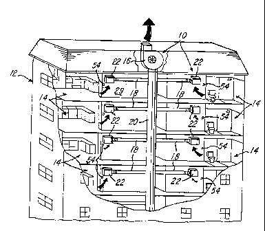
[0043] Referring now to Figs 1-3, a zone control ventilation system or
passive flow
control system 10 for use in the building 12, such as a multi-story commercial
building
(Fig. 1), multi-story condominium or apartment building (Fig. 2), a
residential building
(Fig. 3). The system 10 provides a system, apparatus and method for providing
on-
demand airflow at a demand airflow rate and a passive airflow at a passive
airflow rate
to a plurality of zones or areas 14 in the manner described later herein.
[0044] The system 10 comprises at least one fan 16 (Figs. 1 and 3), or the
system
may comprise a ventilator 17, such as one or more of the multi-port ventilator
series
("MPV") model series MPV ventilator provided by American Aldes Ventilation
Corporation of Sarasota, Florida. It should be understood that other suitable
ventilators
or fans may be used and the invention is not limited by these particular model
types.
[0045] The system 10 further comprises a plurality of ducts 18 that are
coupled
directly to the at least one fan 16 or ventilator 17, as illustrated in Figs 2
and 3, or
9
CA 02570948 2006-12-12
AMA-FL 001 P2
coupled to a main ventilation duct or shaft 20 (Figs. 1 and 11) that is
coupled to either
the at least one fan 16 or ventilator 17. The plurality of ducts 18 are each
coupled to at
least one or a plurality of zone control exhaust terminals 22, at least one of
which is
operatively associated with each of the areas 14 to be ventilated. Although
the
embodiments illustrated in Figs. 1-3 show a single zone control exhaust
terminal 22
associated with each of the areas 14, it should be understood that more than
one of the
plurality zone control exhaust terminals 22 may be associated with each of the
areas 14.
Although not shown, not every area or zone 14 in the building, structure or
residence 12
must have one or more of the plurality of zone control exhaust terminals 22,
although in
a preferred embodiment at least one of the plurality of zone control exhaust
terminals 22
is associated with each area 14.
[0046] Also, while the illustration shown in Fig. 2 shows a multi-port
ventilator 17
coupled directly to each of the plurality of zone control exhaust terminal 22
via ducts 18,
the zone control exhaust terminals 22 may be coupled directly to the main
ventilation
shaft 20 or to artery ducts, such as ducts 18 (Fig. 1), that extend from the
main
ventilation shaft 20. Alternatively, as illustrated in Fig. 11, the terminal
22 may be
situated interior of the shaft, with an open duct extension 30, which in one
embodiment
is at least 22 inches. Note that the duct extension 30 has an end 30a coupled
to the
terminal 22 and an end 30b that is open to the interior area 22c of shaft 20.
It should be
understood that the interior area 22c of shaft 20 has an interior pressure
created or
provided by the at least one fan 16 or ventilator 17.
[0047] Referring to Figs. 4-6, various details of one of the plurality of
zone control
exhaust terminals 22 will now be described. It should be understood that each
of the
plurality of zone exhaust terminals 22 comprise substantially the same parts,
although
they do not have to be identical to each other as will become apparent later
herein.
CA 02570948 2006-12-12
AMA-FL 001 P2
Each of the zone control exhaust terminals 22 comprises a box-shaped housing
24
having a plurality of flanges 26 and 28. The flanges 26 and 28 provide means
for
mounting the housing 24 to a structure, such as between adjacent 10" joists or
trusses
on 16" or 22" centers in a ceiling or roof of the building 12 or between
adjacent studs
(not shown) in a wall 29 (Fig. 1) of the building 12, or to a wall 23 (Fig.
11) of shaft 20.
[0048] As illustrated in Figs. 4 and 6, the housing 24 is generally
rectangular and
comprises the duct extension or collar 30 for coupling the housing 24 to duct
18 and for
communicating with an opening 32 into an area 34 defined by the housing 24.
The duct
collar 30 is conventionally coupled to the duct 18 as illustrated in Fig. 6.
As mentioned
earlier, however, terminal 22 could be mounted to shaft 20 and the end 30b of
duct collar
30 could be open to the interior area 22c of central shaft 20. The housing 24
further
comprises a grille or cover 36 for covering a second opening 38 of the housing
24. The
second opening 38 is associated or in communication with the area or zone 14.
[0049] The system 10 further comprises an air restrictor or damper assembly
40
which will now be described relative to Fig. 5. The assembly 40 comprises a
generally
U-shaped frame or housing 42 having an L-shaped bracket 44 welded or secured
thereto. The apertures 46 and 48 typically support and receive a drive shaft
50 which is
coupled to and pivotally driven by a motor 52 that is operatively coupled to a
switch 54
as shown. The switch 54 may be a wall switch situated on, for example, the
wall, such
as a wall 29 in Fig. 1, associated with the area 14. The switch 54 may be a
manual wall
switch actuated by a user, or the motor 52 may be coupled and respond to at
least one
of a motion sensor, manual control, timer mechanism, light sensor, occupancy
sensor,
CO2 sensor or other indicators or sensors of presence when a user enters or
exits one
of the areas 14.
11
CA 02570948 2006-12-12
AMA-FL 001 P2
[0050] The generally U-shaped support, member bracket 42 is received in the
area
34 (Fig. 4) of housing 24 and secured between housing walls 24a and 24b with a
plurality of screws 56 as shown. Note that the assembly 40 further comprises a
primary
flow control, which in the illustration is a damper 58 that is secured by a
weld, screws or
other suitable means to the drive shaft 50 of motor 52. The damper 58 is
pivotally driven
by the motor 52 in response to a user actuating the switch 54, for example,
from an off
position to an on position. It should be understood that the motor 52 is
operatively
coupled to a power source an AC power source (not shown) in one embodiment,
such
as a 12V, 24V, 120V or 220V AC, but a DC power source may also be used. When
the
switch 54 is actuated by a user to the on position, the motor 52 becomes
energized and
pivotally drives the damper 58 from the closed position to the open position
illustrated in
phantom in Fig. 5.
[0051] It should be noted that the damper 58 is operatively associated with
and
situated adjacent to an opening 32 (Fig. 4) in the wall 24c of housing 24. A
first side 58a
of damper 58 may comprise a foam or other sealing material secured thereto by
an
adhesive for sealing the damper against the surface 24d of housing 24 when the
damper
58 is in the closed position illustrated in Fig. 6. Note that the assembly 40
comprises a
spring or plurality of springs 70 that act upon a joining portion 42b of the
generally U-
shaped support 42 and on the surface 58b of damper 58 to urge or bias the
damper 58
in the direction of arrow A in Fig. 5 so that the damper 58 is biased in the
closed position
illustrated in Fig. 6. The motor 52 retains the damper 58 in the open position
during any
demand period, which is the period in time that the motor 52 is being
activated.
[0052] In one embodiment shown in Figs. 4, 5 and 9A-9B, the assembly 40 may
further comprise a switch 62 that is mounted on a flat area or ledge 42c of
generally U-
shaped bracket 42 as illustrated in Figs. 4 and 5 The switch 62 is operatively
coupled to
12
CA 02570948 2006-12-12
AMA-FL 001 P2
the at least one exhaust fan 16 or ventilator 17 such that when the damper 58
is
actuated or driven from the closed position illustrated in Fig. 6 to the open
position
(shown in phantom in Fig. 5), an edge 58a of damper 58 actuates the lever or
switch 62
coupled to the power source (not shown). When the switch 62 is triggered, the
exhaust
fan 16 or ventilator 17 becomes energized in response, thereby causing an
increase of
airflow in the ducts 18 or shaft 20. When the damper 58 returns to the closed
position,
for example, when the user activates switch 54 to the off position, the damper
58 in the
embodiment shown Figs 9A and 9B is driven or actuated to the closed position
to close
the opening 32 and release the switch 62 to cause at least one fan 16 of
ventilator 17 to
turn off.
[0053] One feature and advantage of this design illustrated in Figs. 4-5
is that it is
easy to perform maintenance on or remove the assembly 40 after it is
installed, although
it is not believed that much maintenance will be required.
[0054] Returning to Figs. 9A-9B, an embodiment is illustrated where the
ventilator 17
or at least one fan 16 is only on when the user actuates the switch 54 to the
on position.
In contrast, the embodiments illustrated in Figs. 7A-7B and Figs. 8A-8B,
described later
herein, does not utilize switch 62 to activate at least one fan 16 or
ventilator 17. In these
embodiments, at least one fan 16 or ventilator 17 provide a constant airflow
in the ducts
18, 19 or shaft 20. However, when a damper 58 in the system 10 is opened in
these
illustrative embodiments, at least one fan 16 or ventilator 17 responds to a
decrease in
duct system resistence or demand for increased airflow and automatically
causes an
increase in fan or ventilator speed, thereby causing a resultant increase in
the airflow in
the shaft 20 and ducts 18 in response and in a manner conventionally known.
[0055] Referring to Figs. 4-6, the assembly 40 further comprises at least
one or a
plurality of airflow regulators 71 and 73 (Fig. 6) and/or 72 and 74 (Figs. 1-
5). In one
13
CA 02570948 2006-12-12
AMA-FL 001 P2
embodiment, the airflow regulators 71 and 73 are integral constant dynamic
airflow
regulators, such as the constant airflow regulators CAR I and CAR II available
from
American Aides Ventilation Corporation, 4537 Northgate Court, Sarasota,
Florida 34234-
2124. As illustrated in Figs. 4 and 5, note that the damper 58 comprises an
aperture or
opening 59 defined by the interior area as shown. The diameter of the interior
wall 58d
in damper 58 is dimensioned to receive the airflow regulator 72 as shown. As
illustrated,
bulb-type constant airflow regulators, such as those regulators 71 and 73
illustrated in
Fig. 6, may be used and these are also available from American Aides
Ventilation
Corporation.
[0056] It should be understood that the constant airflow regulators 72 and
74 may
comprise different specifications in a preferred embodiment and they both
provide
constant airflow regulation. For example, the constant airflow regulators 72
and 74
provide constant airflow regulation by operation of the vane 72a (Fig. 4),
which acts to at
least partially close the opening 72a (Fig. 5) in a manner conventionally
known. In
contrast, the constant airflow regulators 71 and 73 (Fig. 6) provide constant
airflow
regulation by the inflating action of the constant airflow regulator bulb 71a
and 73a,
respectively, and in a manner that is conventionally known. As illustrated in
Fig. 6, note
that the bulbs 71a and 73a are generally hour-glass shaped. As a static
pressure
increases in the ducts 18, the static pressure around the bulbs 71a and 73a,
thereby
causing the bulbs 71a and 73a to inflate and thereby decreasing the area
around the
bulbs 71a and 73a. At substantially the same time, as the static pressure
around the
bulbs 71a and 73a increases, an air velocity also increases thereby resulting
in constant
airflow. The constant airflow regulators 71, 72, 73 and 74 thereby provide a
generally or
substantially constant airflow regardless of pressure differences in the
system 10. Figs.
10A and 10B graphically illustrate the operative characteristics of the
airflow regulators
14
CA 02570948 2006-12-12
AMA-FL 001 P2
71, 72, 73 and 74. It should be understood that the associated specifications
will change
depending upon the specifications selected by the user. The operation of the
system 10
will now be described relative to several illustrative examples shown in Figs.
7A-9B. For
ease of illustration, the embodiment of Figs. 7A-7B will be illustrated or
used in the
embodiment of Fig. 1, Figs. 8A-8B will be illustrated as used in the
embodiment of Fig. 2,
and Figs. 9A-9B will be illustrated as used in the embodiment of Fig. 3.
[0057] In the embodiments shown in Figs. 7A-9B, the damper 58 provides
primary
airflow regulation or control. The damper 58 is used in combination with at
least one of
either the first or second regulator 72 or 74 as illustrated in Figs. 7A-9B.
In
embodiments shown in Figs. 9A-9B, the constant airflow regulator 74 permits a
predetermined amount of airflow and provides substantially constant airflow
regulation to
a predetermined or maximum airflow rate. In contrast, the airflow regulator 72
in the
illustration of Figs. 8A-8B provides substantially constant airflow regulation
at a
predetermined amount or a minimum amount of airflow. When the regulators 72
and 74
are used together as illustrated in Figs. 7A-7B, they control or regulate
airflow to both a
minimum and maximum level, respectively, while the damper 58 controls or
regulates
airflow to a primary demand level, such as an airflow level required to
provide increased
ventilation to a room in response to a demand signal from a user.
[0058] Typical airflow versus pressure difference characteristics are
graphically
illustrated by the graphs under each terminal 22 in Figs. 7A-9B. It should be
understood
that the minimum amount of airflow rate and maximum of airflow rate will be
dependent
upon the size and specifications of the airflow regulators 71, 72, 73, and 74,
respectively, selected. The user's selection of the appropriate constant
airflow regulator
71-74 will depend on the environment or application in which the system 10 is
being
used. In one illustrative embodiment shown in Figs. 7A-7B, the minimum airflow
rate
CA 02570948 2006-12-12
AMA-FL 001 P2
may be on the order of at least 10 cubic feet per minute ("CFM") and the
maximum
amount of airflow rate may be less than or equal to approximately 400 CFM, but
this will
be different depending on the application.
[0059] Returning to Fig. 5, note that the damper 58 is comprised of a
generally
circular planar member 58b lying in a first plane P1 when the damper 58 is in
the closed
position illustrated in Fig. 6. After the constant airflow regulator 72 is
received in the
area 59 defined by wall 58d (Fig. 4) of the planar member 58b, the constant
airflow
regulator 72 lies in the first plane P1 or directly in the airflow path of air
flowing into the
opening 32 (Fig. 4) of housing 22. When the damper 58 is in the closed
position shown
in Figs. 5 and 6, the constant airflow regulator 72 regulates, permits or
controls the
airflow to the constant rate as dictated by the specifications for the
constant airflow
regulator 72 selected by the user. Thus, it should be understood that when the
damper
58 is actuated from closed position to the open position (illustrated in
phantom in Fig. 5
and in the illustration of Figs. 7A-7B and 8A-8B), the airflow regulator 72 is
removed
from the airflow path, thereby removing the minimum or constant airflow
regulator from
the opening 32 and from the airflow path between the area 14 and the duct 18.
[0060] It should be understood that one or both of the constant airflow
regulators 72
and 74 may be used in various combinations, such as the illustrative
combinations that
will now be described relative to Figs. 7A-9B. It should be understood that
the
illustrations in Figs. 7A-9B show the damper assembly 40 (Fig. 4) and
generally U-
shaped member 42 removed from the housing 24 for ease of illustration.
[0061] In the embodiment shown in Figs. 7A-7B, the constant airflow
regulator 72 is
situated in each damper 58 associated with each of the zones or areas 14. The
constant airflow regulator 74 is situated in each duct 18 as shown. In the
illustration in
Figs. 7A-7B, the fan 16 runs continuously at a first fan speed to provide
constant
16
CA 02570948 2006-12-12
AMA-FL 001 P2
ventilation airflow at a first rate. As illustrated in Fig. 7A, as air flows
from the zones or
areas 14 into the ducts 18, the air flows both through the constant airflow
regulator 72
and constant airflow regulator 74. As exhaust air from fan 16, for example, is
pulled
from each zone or area 14 through the duct 18, the constant airflow regulator
72
provides constant airflow regulation to the first predetermined or minimum
level. When
there is a call or demand for increased ventilation in a remote area 14, such
as when the
user in one area 14 actuates the switch 52 to the on position as illustrated
in Fig. 7B, the
damper 58 in the demand area 14 is driven by motor 52 to the open position.
The fan 16
senses the demand and causes increase in speed to a second fan speed. The
dampers
58 in the other remote areas 14 remain closed, as shown by the two leftmost
airflow
regulators 72 shown in Fig. 7B. These regulators 72 provide constant airflow
control or
regulation to the first predetermined or minimum level dictated by the
specifications of
those constant airflow regulators 72. Notice that the increase airflow through
those
constant airflow regulators 72 cause vanes 72a (Fig. 4) to partially close as
shown in
Fig. 7B, thereby controlling or regulating airflow to the desired rate.
Substantially
simultaneously, notice in the right-hand portion of Fig. 7B that the constant
airflow
regulator 72 in the damper 58 has been actuated to the open position and
removed from
the airflow path, thereby permitting increased airflow into and through the
duct 18 from
the area 14 as shown. The second constant airflow regulator 74 controls or
regulates
airflow to the second predetermined maximum level, while the constant airflow
regulators 72 associated with the other zones or areas 14 control or regulate
airflow to
the first or minimum level.
[0062] Thus, the system 10 in the embodiments in Figs. 7A-7B provides
means for
regulating or controlling airflow to the first predetermined or minimum flow
rate in non-
demand areas or zones 14 and between the first predetermined or minimum rate
and
17
CA 02570948 2006-12-12
AMA-FL 001 P2
the second predetermined or maximum rate during demand periods in demand zones
or
areas 14. In other words, the constant airflow regulator 72 in Figs. 7A-7B
facilitate
controlling or regulating airflow to a substantially constant predetermined or
minimum
rate through each of the ducts 18. During ventilation demand periods in those
demand
areas 14 where there is a demand for increased ventilation, such as when a
user
activates switch 54, the damper 58 has been actuated to the open position. As
illustrated by the rightmost assembly in Fig. 7B, at least one fan 16 or
ventilator 17
responds to the pressure drop and increases far speed, causing increased
airflow at the
increased or demand rate in response thereto. This causes increased
ventilation from
the area 14 where increased ventilation is demanded and through duct 18 and,
ultimately, to the exhaust 19 associated with the building 12. Substantially
simultaneously, the constant airflow regulator 72 in the two leftmost ducts
(when viewed
from left to right in Fig. 7B) regulate and control the airflow through the
ducts 18 and so
that airflow continues at substantially the constant rate up to the minimum
airflow rate
which is dictated by the constant airflow regulator 72 selected. The airflow
in the system
is graphically illustrated by the graph under each of the regulators 72 and
74.
[0063] When
the damper 58 in Figs. 7A-7B is closed, the constant airflow regulators
72 or 74 that have the lowest maximum airflow specification will limit or
regulate the
maximum airflow to that specification. For example, if the constant airflow
regulator 72
in Fig. 7A permits a maximum 10 CFM, while constant airflow regulator 74
permits a
maximum airflow of 50 CFM, the airflow will be regulated to 10 CFM in the
illustration
shown in Fig. 7A when the damper 58 is in the closed position. When one of the
dampers 58 in the system 10 is opened, the constant airflow regulator 72,
mounted in
the damper, is removed from the airflow path into opening 32 (Fig. 4), thereby
permitting
airflow at greater than 10 CFM. As the fan 16 or ventilator 17 cause airflow
to increase,
18
CA 02570948 2006-12-12
AMA-FL 001 P2
the regulator 74 regulates airflow through the duct 18 up to the maximum 50
CFM rate
mentioned earlier. The airflow versus pressure characteristic is graphically
illustrated by
the graphs associated with the dampers 58 shown in Figs. 7A-7B.
[0064] Referring back to Figs. 9A and 9B, another illustrative embodiment
is shown.
In this embodiment, the regulator 74 is situated in the duct 18, but regulator
72 is not in
the damper 58. In this embodiment the damper 58 and wall 58b are solid and
only
regulator 74 is used. During normal operation when there is no call or demand
for
ventilation or exhaust the dampers 58 are solid, remain closed and no
ventilation
through the ducts 18, for example, is permitted. The fan 16 or ventilator 17
provide
airflow or turn on in response to the user actuating switch 54 which causes
motor 52 to
drive damper 58 from the closed position to the open position. When there is a
call or
demand for exhaust, the user activates the switch 54 and damper 58 activates
switch
62, as described earlier, to turn on the fan 16 or ventilator 17 to cause an
increased
airflow to a demand rate. The airflow in the two leftmost ducts shown in Fig.
9B are
continued to be blocked by solid damper 58 in this embodiment. The rightmost
open
damper 58 in Fig. 9B is open, but regulator 74 controls or regulates airflow
to the second
predetermined or maximum rate mentioned earlier. The graphs associated with
the
dampers 58 illustrate the airflow versus pressure difference for this
embodiment,
[0065] Figs. 8A and 8B show another embodiment. In this illustration, the
constant
airflow regulator 74 has been removed from the system 10. The regulators 72
permit
minimum flow rate into the ducts 18 when the dampers 58 are in the closed
position.
When one damper 58 is driven by motor 52 to the open position, as illustrated
by the
rightmost damper 58 in Fig. 8B, then unregulated airflow is permitted in the
duct 18
associated with the open damper 58. The constant airflow regulators 72 in the
other
19
CA 02570948 2006-12-12
AMA-FL 001 P2
dampers 58 provide airflow control and regulation to the first predetermined
or minimum
level, as illustrated by the airflow versus pressure graphs in Figs. 8A and
8B.
[0066] Comparing the embodiment of Figs. 7A and 7B to the embodiment of
Figs. 8A
and 8B, notice that the constant airflow regulator 72 associated with the
rightmost duct
18 shown in Fig. 7B has been removed from the direct airflow path between the
zone
area 14 into the duct 18, thereby permitting an increased airflow through the
duct 18.
The second constant airflow regulator 74 in Fig. 7B limits the maximum amount
of
airflow through the duct 18 to the second predetermined amount or the maximum
rate
specified by that constant airflow regulator 74. Substantially simultaneously,
the
constant airflow regulator 72 associated with the two leftmost ducts 18 (as
viewed in Fig.
7B) in the areas or zones 14 where ventilation is not demanded continue to
limit the
amount of airflow to the minimum level amount. In this regard, notice that the
vanes 72a
associated with the two leftmost ducts have closed slightly, thereby limiting
the airflow to
the specification of those constant airflow regulators 72.
[0067] In contrast, the embodiment in Figs. 8A and 8B does not utilize the
regulators
74. Therefore, air flows unregulated into and through the duct 18 associated
with the
damper 58 in the area or zone 14 where ventilation is demanded. No maximum
airflow
control or regulation is provided in the duct 18 associated with that open
damper 58.
[0068] Thus, it should be understood that the system 10 may be provided
with one
or more constant airflow regulators 72 and 74 in various combinations and
arrangements
with damper 58 that is solid or that has a regulator 72 mounted therein to
regulate or
control airflow to a substantially constant minimum and/or maximum level in
the areas
14. On demand, the damper 58 may be actuated from the closed to the open
position
when the user desires to have increased airflow, such as ventilation airflow,
in the zone
or area 14, such as a bathroom.
CA 02570948 2006-12-12
AMA-FL 001 P2
[0069] It should be understood that the regulators 71-74 and features of
the various
embodiments in Figs. 7A-9B may be mixed or interchanged and provided in a
single
system. One illustrative combination is shown in Figs. 12A-12B. For example, a
system
may have dampers 58 with regulators 71 or 72, with or without regulators 73
and 74.
Some dampers 58 may be provided with the solid planar member 58b and without
an
opening 59 similar to the dampers in Fig. 9B, while other dampers 58 and
regulators 72
and 74 may be provided as in the illustrations shown in Figs. 7A-8B.
[0070] As mentioned earlier, it should be understood that while the system
10 and
method have been shown utilizing the switch 54 that may be actuated by the
user, other
means for energizing and actuating the motor 52 to drive the damper 58 from
the closed
position to the open position may be used. For example, the system 10 may
utilize any
suitable means for providing a motor control signal for controlling the motor
52, such as
the switch 54, a dehumidistat or occupancy sensor that senses when an occupant
has
entered or left a room, a timer, a CO2 sensor, or any combination of the
aforementioned
means.
[0071] Advantageously, one feature of the embodiments illustrated is that
it provides
ventilation airflow regulation or control from the zones or areas 14 through
at least one
or a plurality of the ducts 18 to a maximum airflow rate or less or between
minimum and
maximum airflow rates. Note that the step of permitting airflow from the fan
16 or
ventilator 17 is performed passively utilizing one or more of the constant
airflow
regulators 72 or 74.
[0072] Advantageously, the aforementioned embodiments provide a primary
flow
controller or regulator in the form of the damper 58 and at least one or a
plurality of other
flow controllers or regulators, such as the constant airflow regulators 71 and
72. These
21
CA 02570948 2006-12-12
AMA-FL 001 P2
airflow regulators may be used alone or in combination with another constant
airflow
regulator 73 or 74.
[0073] As mentioned earlier, one advantage of the embodiment of Figs. 4-6
is that
maintenance is much improved over prior art systems because the assembly 40
can be
completely removed from the housing 24 without having to disconnect the
housing 24 or
terminal 22 from any ducts or shafts. It should also be understood that the
constant
airflow regulators 71-74 require little or no routine maintenance, unlike the
electrical and
mechanical systems of the past.
[0074] The housing 24 does not have to be disconnected from the duct 18
if it is
necessary to make any repairs or maintenance. The flow control device, such as
regulators 72 and 74, require no direct electrical or pneumatic power source,
and can
regulate and control the airflow by utilizing only system duct pressure. Thus,
even if
there is no power to switch 54 or motor 52, the regulators 72 and/or 74 will
continue to
regulate airflow.
[0075] Another feature of one embodiment is the small size of the terminal
22, which
has dimensions of 10" x 10" x 8". The terminal 22 is capable of being mounted
between
floor, and ceiling assemblies, such as those constructed of standard joists on
16"
centers.
[0076] Because the system 10 is capable of regulating and controlling
airflow in the
various zones or areas 14 on an as needed basis, the overall capacity
requirements of
the central fan 16 and/or ventilator 17 can be reduced because the system10 is
capable
of providing constant airflow in non-demand areas 14 and airflow at a demand
rate in
those areas where increased airflow or ventilation is demanded. This enables a
smaller
fan 16 or ventilator to be utilized in the system 10.
22
CA 02570948 2014-06-09
[0077] The system 10 advantageously provides a flow control device that
regulates
airflow to constant levels when exposed to varying duct pressure.
[0078] While the method herein described, and the form of apparatus for
carrying
this method into effect, constitute preferred embodiments of this invention,
it is to be
understood that the invention is not limited to this precise method and form
of apparatus,
and that changes may be made in either without departing from the scope of the
inventions, which is defined in the appended claims.
23