Language selection

Search

Patent 2572372 Summary

Third-party information liability

Some of the information on this Web page has been provided by external sources. The Government of Canada is not responsible for the accuracy, reliability or currency of the information supplied by external sources. Users wishing to rely upon this information should consult directly with the source of the information. Content provided by external sources is not subject to official languages, privacy and accessibility requirements.

Claims and Abstract availability

Any discrepancies in the text and image of the Claims and Abstract are due to differing posting times. Text of the Claims and Abstract are posted:

  • At the time the application is open to public inspection;
  • At the time of issue of the patent (grant).
(12) Patent Application: (11) CA 2572372
(54) English Title: DISK BRAKE FOR VEHICLES WITH A CLAMPING DEVICE HAVING A NEEDLE BEARING
(54) French Title: FREIN A DISQUE POUR VEHICULES COMPRENANT UN DISPOSITIF DE SERRAGE MUNI D'UN ROULEMENT A AIGUILLES
Status: Deemed Abandoned and Beyond the Period of Reinstatement - Pending Response to Notice of Disregarded Communication
Bibliographic Data
(51) International Patent Classification (IPC):
  • F16D 65/18 (2006.01)
(72) Inventors :
  • BIRKENEDER, FRANZ-JOSEF (Germany)
(73) Owners :
  • KNORR-BREMSE SYSTEME FUER NUTZFAHRZEUGE GMBH
(71) Applicants :
  • KNORR-BREMSE SYSTEME FUER NUTZFAHRZEUGE GMBH (Germany)
(74) Agent: SMART & BIGGAR LP
(74) Associate agent:
(45) Issued:
(86) PCT Filing Date: 2005-06-30
(87) Open to Public Inspection: 2006-01-12
Availability of licence: N/A
Dedicated to the Public: N/A
(25) Language of filing: English

Patent Cooperation Treaty (PCT): Yes
(86) PCT Filing Number: PCT/EP2005/007025
(87) International Publication Number: WO 2006002905
(85) National Entry: 2006-12-28

(30) Application Priority Data:
Application No. Country/Territory Date
10 2004 031 792.5 (Germany) 2004-07-01

Abstracts

English Abstract


The invention relates to a disk brake for vehicles, in particular to a
pneumatically actuated disk brake for utility vehicles, comprising a brake
saddle and a clamping device for clamping the brake. Said clamping device has
a first component in the form of a rotary lever which is displaceably guided
on a second element, such as a brake saddle, by means of a needle bearing (1).
According to the invention, the disk brake is characterized in that the inner
ring (3) is embodied as a bearing cage made of plastic, said cage enclosing on
its outside an evenly configured ring of sheet metal serving as exterior
bearing.


French Abstract

L'invention concerne un frein à disque pour des véhicules, notamment un frein à disque à actionnement pneumatique pour des véhicules utilitaires. Le frein à disque selon l'invention comprend un étrier de frein, ainsi qu'un dispositif de serrage servant à serrer le frein et présentant un premier élément comme un levier rotatif qui est guidé déplaçable au moyen d'un roulement à aiguilles (1) sur un deuxième élément, tel un étrier de frein. Le frein à disque selon l'invention est caractérisé en ce que la bague intérieure (3) est réalisée sous forme de cage de roulement en plastique qui enveloppe latéralement une bague de tôle plane servant de palier extérieur.

Claims

Note: Claims are shown in the official language in which they were submitted.

-6-
claims
1. A disk brake for vehicles, in particular a
pneumatically actuated disk brake for commercial
vehicles, having
a) a brake caliper and
b) an application device, which is arranged in the
brake caliper, for applying the brake,
c) with the application device having a first
component, preferably a rotary lever, which is
mounted in a moveable fashion on a second
component, such as a brake caliper, by means of a
needle bearing (1) having a set of bearing needles
(4), an outer ring (2) and an inner ring (3) which
is embodied as a bearing cage,
d) with the outer ring (2) and the inner ring (3)
having the geometry of a section of a circular
arc,
characterized in that
e) the inner ring (3) which is embodied as a bearing
cage is made from plastic and engages in a U-
shaped fashion around a sheet metal ring as an
outer bearing.
2. The disk brake as claimed in claim 1,
characterized in that the inner ring (3) is
provided with two lateral cage walls (5) which are
aligned outward perpendicular to the inner ring
and extend in the direction of the outer ring (2)
and laterally border the latter.
3. The disk brake as claimed in claim 1 or 2,
characterized in that the outer ring (2) is
produced from a planar metal sheet which is bent
into the shape of a circular arc.

-7-
4. The disk brake as claimed in one of the preceding
claims, characterized in that the outer ring (2)
has lateral cut-outs (6, 7) at two opposite sides,
into which lateral cut-outs (6, 7) the cage walls
(5) of the inner ring (3) engage.
5. The disk brake as claimed in one of the preceding
claims, characterized in that the cut-outs (6, 7)
extend in such a manner that the inner ring is
guided in the cut-outs of the outer ring (2) so as
to be moveable to a limited extent, so that the
cut-outs (6, 7) assume the function of movement-
limiting stops.

Description

Note: Descriptions are shown in the official language in which they were submitted.


CA 02572372 2006-12-28
DISK BRAKE FOR VEHICLES WITH A CLAMPING DEVICE
HAVING A NEEDLE BEARING
The invention relates to a disk brake for vehicles, in
particular a pneumatically actuated disk brake for
commercial vehicles, as claimed in the preamble of
claim 1.
Generic disk brakes are known in various embodiments,
for example under the product designations SB6 and SB7
and also SN6 and SN7 of the applicant of this property
right. The invention is particularly suitable for use
in brakes of said type but is also suitable in
principle for other types of disk brake in which a
first moveable brake component, in particular a rotary
lever which is to be mounted eccentrically, is mounted
on a further brake component by means of a circular-
arc-shaped needle bearing. Here, the terms "outer ring"
and "inner ring" do not denote closed rings but rather
components which extend in an arcuate fashion over part
of a circle.
Needle bearings or rolling bearings having an outer
ring, an inner ring and a set of bearing needles have
been proven per se for mounting brake parts which are
moveable relative to one another. A need for
optimization is seen in particular in the relatively
high cost expenditure in producing needle bearings of
said type.
The object of the invention is to solve this problem.
The invention achieves this object by means of the
subject matter of claim 1.
According to claim 1, the inner ring is embodied as a
plastic bearing cage which engages in a u-shaped

CA 02572372 2006-12-28
- 2 -
fashion around a "planar" sheet metal ring as an outer
bearing. Since the outer ring is composed of a metal
sheet, which with the exception of the functional
elements such as lugs or the like can be produced in a
simple manner in one single bending process, and since
the function of the lateral cage walls is assumed by
the plastic inner ring which can be produced in a cost-
effective manner for example as an injection-molded
part, the costs of producing the needle bearing and
therefore the costs of producing the disk brake can be
lowered while nevertheless providing functionality
which is the same as or improved over that of the prior
art. According to the prior art, in contrast, the outer
ring was manufactured as a sheet metal arc with two
lateral cage walls which could be attached to the very
hard metal sheet which was to be used only by means of
complex and expensive production processes. Counter to
previous expectations, however, it is possible for the
function of laterally delimiting the cage to be moved
to the plastic inner ring.
Advantageous embodiments can be gathered from the
subclaims.
The invention is explained in more detail below on the
basis of an exemplary embodiment and with reference to
the drawing, in which:
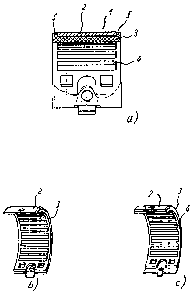
Figures la-e show various views of a needle bearing
according to the invention; and
Figures 2a-b show one perspective view and one
partially sectioned view of an inner
ring of the needle bearing from figure 1
Figure 3 shows a perspective view of the outer
ring of the needle bearing from figure
1.

CA 02572372 2006-12-28
- 3 -
Figure 1 shows a needle bearing 1 for a disk brake (not
otherwise illustrated here), which needle bearing 1 can
be used in particular for mounting the rotary lever for
example on the brake caliper of a disk brake as is
known for example under the product designations SN6 or
SN 7 or else as is known in a similar design for
example from DE 4204307 A (see the rolling bearing 3 in
said document) or DE 197 31 696 A. With regard to the
design of disk brakes of said type, which is not
discussed in any more detail here, reference is made to
the entire contents of said documents.
The needle bearing or rolling bearing 1 illustrated in
figure 1 has a circular-arc-shaped outer ring 2 and an
associated inner ring 3, between which a set of bearing
needles 4 is arranged in such a way that the outer ring
2 is mounted so as to be rotationally moveable relative
to the inner ring 3.
The inner ring 3 is composed of plastic and is provided
with two lateral cage walls 5 - see also figure 2 -
which are aligned outward perpendicular to the inner
ring and extend in the direction of the outer ring 2
and laterally border the latter in a u-shaped fashion.
The outer ring 2 - see also figure 3 - is produced from
a planar metal sheet which has been bent to form a
cylindrical section or into the shape of a circular
arc. Said outer ring 2 has, at its sides, two lateral
cut-outs 6, 7 into which the cage walls 5 of the inner
ring engage, with the cut-outs 6, 7 extending in such a
manner that the inner ring is guided in the cut-outs of
the outer ring 2 so as to be moveable to a limited
extent, so that the cut-outs 6, 7 firstly assume the
function of movement-limiting stops in a simple manner
and secondly serve to correctly guide the outer ring 2
on the inner ring 3 and retain the outer ring 2 in the

CA 02572372 2006-12-28
- 4 -
installed position.
Fastening devices such as lugs 8 and/or bores 9 fix the
inner ring 3 and/or the outer ring 2 to the
respectively associated components which are to be
mounted so as to be moveable relative to one another,
such as the brake caliper and the rotary lever of the
disk brake (not illustrated here).
The plastic inner ring 3 has a plurality of cut-out-
like chambers 10 for accommodating in each case two of
the bearing needles 4. The sheet metal outer ring 2 is,
in contrast, composed of a metal sheet which with the
exception of the lugs 9 can be produced in a simple
manner in only one single bending process, so that the
needle bearing according to the invention can be
produced considerably more cost-effectively than the
known needle bearing without any impairment in
functionality.

CA 02572372 2006-12-28
- 5 -
Reference symbols
Needle bearing 1
Outer ring 2
Inner ring 3
Bearing needles 4
Cage walls 5
Cut-outs 6, 7
Lugs 8
Bores 9
Chambers 10

Representative Drawing
A single figure which represents the drawing illustrating the invention.
Administrative Status

2024-08-01:As part of the Next Generation Patents (NGP) transition, the Canadian Patents Database (CPD) now contains a more detailed Event History, which replicates the Event Log of our new back-office solution.

Please note that "Inactive:" events refers to events no longer in use in our new back-office solution.

For a clearer understanding of the status of the application/patent presented on this page, the site Disclaimer , as well as the definitions for Patent , Event History , Maintenance Fee  and Payment History  should be consulted.

Event History

Description Date
Time Limit for Reversal Expired 2011-06-30
Application Not Reinstated by Deadline 2011-06-30
Inactive: Abandon-RFE+Late fee unpaid-Correspondence sent 2010-06-30
Deemed Abandoned - Failure to Respond to Maintenance Fee Notice 2010-06-30
Inactive: IPRP received 2008-02-15
Inactive: Correspondence - Transfer 2007-06-05
Letter Sent 2007-04-19
Inactive: Courtesy letter - Evidence 2007-03-06
Inactive: Cover page published 2007-03-05
Inactive: Notice - National entry - No RFE 2007-02-28
Inactive: Applicant deleted 2007-02-28
Inactive: Single transfer 2007-02-27
Application Received - PCT 2007-01-30
National Entry Requirements Determined Compliant 2006-12-28
Application Published (Open to Public Inspection) 2006-01-12

Abandonment History

Abandonment Date Reason Reinstatement Date
2010-06-30

Maintenance Fee

The last payment was received on 2009-06-22

Note : If the full payment has not been received on or before the date indicated, a further fee may be required which may be one of the following

  • the reinstatement fee;
  • the late payment fee; or
  • additional fee to reverse deemed expiry.

Please refer to the CIPO Patent Fees web page to see all current fee amounts.

Fee History

Fee Type Anniversary Year Due Date Paid Date
Basic national fee - standard 2006-12-28
Registration of a document 2007-02-27
MF (application, 2nd anniv.) - standard 02 2007-07-03 2007-05-07
MF (application, 3rd anniv.) - standard 03 2008-06-30 2008-05-08
MF (application, 4th anniv.) - standard 04 2009-06-30 2009-06-22
Owners on Record

Note: Records showing the ownership history in alphabetical order.

Current Owners on Record
KNORR-BREMSE SYSTEME FUER NUTZFAHRZEUGE GMBH
Past Owners on Record
FRANZ-JOSEF BIRKENEDER
Past Owners that do not appear in the "Owners on Record" listing will appear in other documentation within the application.
Documents

To view selected files, please enter reCAPTCHA code :


To view images, click a link in the Document Description column. To download the documents, select one or more checkboxes in the first column and then click the "Download Selected in PDF format (Zip Archive)" or the "Download Selected as Single PDF" button.

List of published and non-published patent-specific documents on the CPD .

If you have any difficulty accessing content, you can call the Client Service Centre at 1-866-997-1936 or send them an e-mail at CIPO Client Service Centre.


Document
Description 
Date
(yyyy-mm-dd) 
Number of pages   Size of Image (KB) 
Drawings 2006-12-28 4 59
Description 2006-12-28 5 143
Claims 2006-12-28 2 45
Abstract 2006-12-28 1 16
Representative drawing 2007-03-02 1 8
Cover Page 2007-03-05 2 44
Reminder of maintenance fee due 2007-03-01 1 110
Notice of National Entry 2007-02-28 1 192
Courtesy - Certificate of registration (related document(s)) 2007-04-19 1 105
Reminder - Request for Examination 2010-03-02 1 119
Courtesy - Abandonment Letter (Maintenance Fee) 2010-08-25 1 174
Courtesy - Abandonment Letter (Request for Examination) 2010-10-06 1 164
PCT 2006-12-29 4 220
PCT 2006-12-28 6 192
Correspondence 2007-02-28 1 28
Fees 2007-05-07 1 35
Fees 2009-06-22 1 35