Language selection

Search

Patent 2572683 Summary

Third-party information liability

Some of the information on this Web page has been provided by external sources. The Government of Canada is not responsible for the accuracy, reliability or currency of the information supplied by external sources. Users wishing to rely upon this information should consult directly with the source of the information. Content provided by external sources is not subject to official languages, privacy and accessibility requirements.

Claims and Abstract availability

Any discrepancies in the text and image of the Claims and Abstract are due to differing posting times. Text of the Claims and Abstract are posted:

  • At the time the application is open to public inspection;
  • At the time of issue of the patent (grant).
(12) Patent: (11) CA 2572683
(54) English Title: JOINT STRUCTURE FOR A BRACKET AND A COMPONENT BODY
(54) French Title: PIECES EQUIPEES D'UNE PATTE DE FIXATION
Status: Granted and Issued
Bibliographic Data
(51) International Patent Classification (IPC):
  • B23K 1/00 (2006.01)
(72) Inventors :
  • MATSUNAGA, HIDEAKI (Japan)
(73) Owners :
  • SANOH INDUSTRIAL CO., LTD.
(71) Applicants :
  • SANOH INDUSTRIAL CO., LTD. (Japan)
(74) Agent: MOFFAT & CO.
(74) Associate agent:
(45) Issued: 2012-03-13
(86) PCT Filing Date: 2005-06-03
(87) Open to Public Inspection: 2006-01-19
Examination requested: 2007-01-03
Availability of licence: N/A
Dedicated to the Public: N/A
(25) Language of filing: English

Patent Cooperation Treaty (PCT): Yes
(86) PCT Filing Number: PCT/JP2005/010638
(87) International Publication Number: WO 2006006329
(85) National Entry: 2007-01-03

(30) Application Priority Data:
Application No. Country/Territory Date
2004-201346 (Japan) 2004-07-08

Abstracts

English Abstract


It is an object to provide a component provided with a
bracket, in which soldering deficiencies seldom occur when
soldering a bracket that has a bead to the component body, and
moreover, in which plating liquid does not remain when plating
is carried out. And in order to achieve this object, in a
component provided with a bracket in which a bracket 2 having a
bead 3 formed thereon is joined to the component body 1 such that
an end portion 3a of the bead 3 faces the component body 1, a
hole 6 is provided penetrating the end portion 3a of the bead 3,
and a cavity portion 7 defined by the bracket 2 and the component
body 1 is made open to outside through the hole 6.


French Abstract

Fournir des pièces équipées d'une patte de fixation qui peuvent être difficiles à casser par brasage lorsque la patte de fixation est brasée sur le corps de la pièce et qui peuvent aussi être exemptes de captage d'une solution de placage en cas de placage métallique de celles-ci. Les pièces comprenant une patte de fixation (2) ayant une nervure (3) formée dessus et la patte de fixation étant jointe à la pièce de sorte que l'extrémité (3a) de la nervure (3) soit face au corps (1) de la pièce, caractérisées par le fait qu'un orifice (6) est fourni sur l'extrémité (3a) de la nervure (3) et qu'une partie creuse (7) formée par la couverture (2) et le corps (1) de la pièce est ouverte sur son extérieur par ledit orifice (6).

Claims

Note: Claims are shown in the official language in which they were submitted.

CLAIMS
1. A structure of a joint portion of a component body and
a bracket, the bracket formed in a substantial crank-shape in a
longitudinal direction, the bracket having a bead formed thereon
so as to reinforce the bracket, the bracket being joined to the
component body by soldering such that an underside of an end
portion of the bead touches the component body and a cavity is
formed at a juncture between the component body and the underside
of the end portion of the bead, the joined component body and the
bracket are plated, said structure of the joint portion of the
component body and the bracket comprising:
a hole penetrating through the end portion of the bead into
the cavity so as to open the cavity to the outside through the
hole so that soldering material may enter the juncture between
the component body and the bracket through the hole when
soldering is performed and so that plating liquid may flow in and
out of the cavity through the hole when plating is performed,
wherein the bead is an embossed line spanning from near an end
portion of the bracket to an intermediate portion of the bracket.
2. The structure of the joint portion of the component
body and the bracket of claim 1, wherein a width of said hole is
not less than an inner width of said bead.
8

3. The structure of the joint portion of the component
body and the bracket of claim 1 or 2, wherein said bracket is
joined to said component body by furnace soldering.
9

Description

Note: Descriptions are shown in the official language in which they were submitted.


CA 02572683 2009-11-16
JOINT STRUCTURE FOR A BRACKET AND A COMPONENT BODY
TECHNICAL FIELD
The present invention relates to a component provided with
a bracket, and more particularly to a component provided with a
bracket suitable for joining the bracket and the component body
by furnace soldering or carrying out plating on the bracket and
the component body.
BACKGROUND ART
In components such as the inflators employed in side air
bags for example, the inflator housing is attached to the
attachment target portion, such as a car body or a seat back, by
way of a bracket.
In such cases, the end portion of the bracket is welded to
the inflator housing as described in Japanese Patent Application
Laid-open No. 2001-63511 for example. Moreover, beads are
generally formed on such brackets for the purpose of reinforcing
the brackets.
In this regard, as shown in FIG. 4, when a bracket 12 is
joined to an inflator housing 11 by furnace soldering, due to air
resistance or the like, the solder material sometimes does not
flow into a cavity portion 14 that is formed by a peripheral
surface of the inflator housing 11 and a concave portion of a
bead 13 on the bracket 12, such that there is a risk of deficient
soldering. Furthermore, in the case of carrying out plating, a
1

CA 02572683 2011-06-20
plating liquid that enters the cavity portion 14 in a plating
tank may remain inside the cavity portion 14 due to surface
tension or the like even after the work is raised out of the
plating tank, which poses a risk of corrosion if left as it is.
Accordingly, with the foregoing in view, it is an object of
the present invention to provide a component provided with a
bracket, in which soldering deficiencies seldom occur when
soldering a bracket that has a bead to the component body, and
moreover, in which plating liquid does not remain when plating
1o is carried out.
DISCLOSURE OF THE INVENTION
In order to solve the above-described problems, in the
present invention, there is provide a structure of a joint
portion of a component body and a bracket, the bracket formed in
a substantial crank-shape in a longitudinal direction, the
bracket having a bead formed thereon so as to reinforce the
bracket, the bracket being joined to the component body by
soldering such that an underside of an end portion of the bead
touches the component body and a cavity is formed at a juncture
between the component body and the underside of the end portion
of the bead, the joined component body and the bracket are
plated, the structure of the joint: portion of the component body
and the bracket comprising: a hole penetrating through the end
portion of the bead into the cavity so as to open the cavity to
the outside through the hole so that soldering material may enter
2

CA 02572683 2011-06-20
the juncture between the component body and the bracket through
the hole when soldering is performed and so that plating liquid
may flow in and out of the cavity through the hole when plating
is performed, wherein the bead is an embossed line spanning from
near an end portion of the bracket to an intermediate portion of
the bracket.
Here, the shape of the component may be any shape.
With a component provided with a bracket according to the
present invention, when the bracket is joined to the component
body by soldering and when the soldering material enters a cavity
portion formed by the component body and the bracket, the cavity
portion is made open to the outside through the hole, and
therefore the soldering material is not easily affected by
resistance due to air and can easily enter the juncture portion
between the component body and the bracket, thereby soldering can
be performed stably. Furthermore, when a component, in which a
bracket has been joined to the component body, undergoes plating,
even if the plating liquid or the like enters the cavity portion,
there is no risk that the plating liquid remains in the cavity
portion since it is released outside from the hole formed at the
end portion of the bead.
Consequently, it is possible to achieve a component provided
with a bracket having good quality.
Furthermore, in the present invention, a width of the hole
is formed not less than the inner width of the bead.
3

CA 02572683 2011-06-20
Here, the shape of the hole is not limited to a round shape
and may be a shape that allows withdrawal of the curved portion
of the end portion of the bead.
With a component provided with a bracket according to the
present invention, the end portion of the cavity portion formed
by the component body and the bead of the bracket is made
completely open to the outside, and therefore the soldering
material very reliably enters the juncture portion between the
component body and the bracket when soldering is performed.
Furthermore, when plating is performed, plating liquid that has
entered the cavity portion does not remain there and is
completely released to the outside.
Consequently, it is possible to achieve a component provided
with a bracket having good quality.
According to the present invention, said hole is so formed
that the plating liquid can be easily released to the outside.
The hole in a component comprising a bracket, according to the
present invention, functions well not only for releasing gas at
soldering, but also for releasing plating liquid from the inner
cavity portion to the outside, in spite of a high viscosity and
high surface tension of plating liquid. The plating liquid,
thus, can be perfectly removed from the inner cavity. As a
result, it is possible to achieve a component provided with a
bracket well plated with no risk of corrosion and having high
durability.
4

CA 02572683 2011-06-20
BRIEF DESCRIPTION OF THE DRAWINGS
FIG. 1 is a perspective view schematically showing a portion
of an inflator of a side air bag as a component provided with a
bracket according to the present invention;
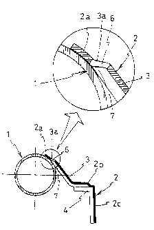
FIG. 2 is a cross-sectional view along a line A-A in FIG. 1;
FIGS. 3(a) and 3(b) show brackets as viewed from the rear,
with FIG. 3(a) being a bracket on. which two thin beads are formed
and FIG. 3(b) being a bracket on which two thick beads are
formed; and
FIG. 4 is a cross-sectional view of a component provided
with a bracket of a conventional structure in which the bracket
is joined to the inflator housing.
BEST MODE FOR CARRYING OUT THE INVENTION
The following is a detailed description of the present
invention using an inflator of a side air bag as an example of
a component provided with a bracket, with reference to the
accompanying drawings.
The inflator shown in FIGS. 1 and 2 is structured such that
a bracket 2 is joined to a cylindrical inflator housing 1.
The bracket 2 is formed in a substantial crank-shape in a
longitudinal direction and two beads 3 are formed spanning from
an end portion 2a to an intermediate portion 2b. Furthermore, at
the intermediate portion 2b and a base portion 2c of the
bracket 2, flanges 4, 4 are formed facing inward from side
5

CA 02572683 2011-06-20
portions thereof, and a hole 5 is formed at a central portion in
the width direction of the base portion 2c, for attaching the
bracket 2 to a car body or seat (not shown) or the like.
Furthermore, in the bracket 2, holes 6 are provided
penetrating through end portions 3a of the beads 3. It is
preferable that the holes 6 are formed so as to have a width not
less than the inner width of the beads 3 as shown in FIGS. 3(a)
and 3(b), but the shape thereof is not limited to a round shape,
and may be a shape that allows withdrawal of the curved portion
of the end portions 3a of the beads 3.
As shown in FIG. 2, the end portion 2a of the bracket 2 is
brought into contact with the peripheral surface of the inflator
housing 1 such that the end portions 3a of the beads 3 touch the
peripheral surface thereof. In this state, the bracket is
provisionally attached to the inflator housing 1 using resistance
welding or TIG welding or the like, and then furnace soldering
is carried out.
At this time, a soldering material enters a cavity portion 7
formed by the peripheral surface of the inflator housing 1 and
an inner surface of the end portion 3a of the bead 3 of the
bracket 2, and the soldering material flows into the entire
juncture portion between the inflator housing 1 and the bracket 2
of the cavity portion 7, such that the juncture portion is
uniformly joined.
6

CA 02572683 2011-06-20
Following this, the inflator housing 1 to which the
bracket 2 is joined undergoes plating.
At this time, the plating liquid enters the cavity
portion 7, but the plating liquid does not remain in the cavity
portion 7 since it escapes outward from the holes 6.
In this way, the inflator housing 1, to which the bracket 2
is soldered and which undergoes plating, is fastened to a car
body or a seat (not shown) or the like using a bolt (not shown)
that inserts through the hole 5.
It should be noted that a component provided with a bracket,
in which the bracket 2 was joined to the inflator housing 1, was
shown in the abovementioned embodiment, but of course the
structure of the present invention can be applied to components
provided with other brackets.
INDUSTRIAL APPLICABILITY
With a component provided with a bracket according to the
present invention described above, soldering can be performed
stably when the bracket is joined to the component body by
soldering and, moreover, it is possible to achieve uniform
plating without plating liquid remaining in the cavity portions
of the beads when the component, to which the bracket has been
joined, undergoes plating. For this reason, the present invention
can be used for all components provided with a bracket, on which
a bead is formed and which is joined to the component body such
that an end portion of the bead faces the component.
7

Representative Drawing
A single figure which represents the drawing illustrating the invention.
Administrative Status

2024-08-01:As part of the Next Generation Patents (NGP) transition, the Canadian Patents Database (CPD) now contains a more detailed Event History, which replicates the Event Log of our new back-office solution.

Please note that "Inactive:" events refers to events no longer in use in our new back-office solution.

For a clearer understanding of the status of the application/patent presented on this page, the site Disclaimer , as well as the definitions for Patent , Event History , Maintenance Fee  and Payment History  should be consulted.

Event History

Description Date
Common Representative Appointed 2019-10-30
Grant by Issuance 2012-03-13
Inactive: Cover page published 2012-03-12
Inactive: Final fee received 2012-01-03
Pre-grant 2012-01-03
Notice of Allowance is Issued 2011-10-04
Inactive: Office letter 2011-10-04
Letter Sent 2011-10-04
Notice of Allowance is Issued 2011-10-04
Inactive: Approved for allowance (AFA) 2011-09-23
Amendment Received - Voluntary Amendment 2011-06-20
Inactive: S.30(2) Rules - Examiner requisition 2011-01-26
Amendment Received - Voluntary Amendment 2010-09-07
Inactive: S.30(2) Rules - Examiner requisition 2010-03-17
Amendment Received - Voluntary Amendment 2009-11-16
Inactive: S.30(2) Rules - Examiner requisition 2009-05-28
Inactive: IPRP received 2008-02-18
Letter Sent 2007-08-02
Inactive: Single transfer 2007-06-11
Inactive: Cover page published 2007-03-07
Inactive: Courtesy letter - Evidence 2007-03-06
Inactive: Acknowledgment of national entry - RFE 2007-02-28
Letter Sent 2007-02-28
Application Received - PCT 2007-02-01
National Entry Requirements Determined Compliant 2007-01-03
Request for Examination Requirements Determined Compliant 2007-01-03
All Requirements for Examination Determined Compliant 2007-01-03
Application Published (Open to Public Inspection) 2006-01-19

Abandonment History

There is no abandonment history.

Maintenance Fee

The last payment was received on 2011-05-04

Note : If the full payment has not been received on or before the date indicated, a further fee may be required which may be one of the following

  • the reinstatement fee;
  • the late payment fee; or
  • additional fee to reverse deemed expiry.

Please refer to the CIPO Patent Fees web page to see all current fee amounts.

Owners on Record

Note: Records showing the ownership history in alphabetical order.

Current Owners on Record
SANOH INDUSTRIAL CO., LTD.
Past Owners on Record
HIDEAKI MATSUNAGA
Past Owners that do not appear in the "Owners on Record" listing will appear in other documentation within the application.
Documents

To view selected files, please enter reCAPTCHA code :


To view images, click a link in the Document Description column. To download the documents, select one or more checkboxes in the first column and then click the "Download Selected in PDF format (Zip Archive)" or the "Download Selected as Single PDF" button.

List of published and non-published patent-specific documents on the CPD .

If you have any difficulty accessing content, you can call the Client Service Centre at 1-866-997-1936 or send them an e-mail at CIPO Client Service Centre.


Document
Description 
Date
(yyyy-mm-dd) 
Number of pages   Size of Image (KB) 
Description 2007-01-03 8 219
Drawings 2007-01-03 4 43
Abstract 2007-01-03 1 18
Claims 2007-01-03 1 21
Representative drawing 2007-03-06 1 6
Cover Page 2007-03-07 1 37
Abstract 2009-11-16 1 17
Claims 2009-11-16 1 25
Description 2009-11-16 7 227
Drawings 2009-11-16 4 43
Description 2010-09-07 7 233
Claims 2010-09-07 2 44
Description 2011-06-20 7 247
Claims 2011-06-20 2 39
Representative drawing 2012-02-15 1 7
Cover Page 2012-02-15 1 38
Acknowledgement of Request for Examination 2007-02-28 1 176
Reminder of maintenance fee due 2007-02-28 1 110
Notice of National Entry 2007-02-28 1 201
Courtesy - Certificate of registration (related document(s)) 2007-08-02 1 104
Commissioner's Notice - Application Found Allowable 2011-10-04 1 163
PCT 2007-01-03 5 163
Correspondence 2007-02-28 1 26
Fees 2007-05-09 1 58
PCT 2007-01-04 3 90
Fees 2008-05-07 1 64
Fees 2009-05-04 1 56
Fees 2010-05-31 1 56
Fees 2011-05-04 1 45
Correspondence 2011-10-04 1 30
Correspondence 2012-01-03 1 44
Fees 2012-04-13 1 46