Note: Descriptions are shown in the official language in which they were submitted.
CA 02572704 2007-01-02
WO 2006/003438 PCT/GB2005/002627
1
83884/03
Crush Modelling
Field of the Invention
This invention relates to methods, apparatus and software for modelling the
behaviour of materials which are crushed particularly, but not exclusively, in
the
context of composite vehicle body parts under impact.
Background
It has been recognised for a long time that fiber-reinforced composite
materials, particularly carbon fiber composites have great potential for
revolutionising the auto industry. It is well known that composites are very
light
compared to their metal equivalents, even aluminium, and can be formed into
complex shapes that can do the same job as many welded metal stampings.
Composites also have the ability to absorb high amounts of energy during
impacts which make them ideal for automotive, rail or civil applications. For
example, whereas steel can only absorb up to 20 kilojoules per kilogramme and
aluminium approximately 30 kilojoules per kilogramme, carbon composites can
absorb up to 80 kilojoules per kilogramme.
In addition, unlike metallic structures, the crushed material has very little
residual strength after it has absorbed the energy. Instead, the composite
material is
essentially transformed into small pieces of debris and loosely connected
fibres after
it has been crushed which means that less space is required than in an
equivalent
metal structure. This is because in a metal structure space must be provided
in
designated crumple zones to accommodate the buckled metal.
There is, therefore, a significant incentive to using composite materials such
as carbon fiber composites in mass production vehicles. However, to date they
have
only been used in very limited applications such as top-end sports cars, motor
sport
and small, non-critical parts of mass produced cars.
Two significant current disadvantages of composites is that they are
relatively costly and have long manufacturing cycle times. However, a
significant
CA 02572704 2007-01-02
WO 2006/003438 PCT/GB2005/002627
2
barrier which still remains to their widespread use in the automotive industry
is the
ability to be able to model their performance in an impact. This is of course
essential to be able to do in order to design vehicles which are as safe as
possible
and which will behave in a predictable way in the event of a crash. Although
crash
performance testing can be carried out by building prototypes, this is
extremely
expensive and is only practically feasible in the latter stages of design to
prove the
basic design and calibrate restraint systems. During the earlier stages of
design of
vehicles made from metal, fmite element analysis is used to model the
behaviour
and interaction of the various metal parts and to predict their performance in
the
event of an impact. This means that designs can be proposed, tested and
modified
using computer modelling with much less reliance on producing and testing
expensive prototypes.
However, this approach does not currently work for crushable materials such
as composites. The reason for this is that composites absorb energy by a very
different mechanism to metallic structures. Metallic structures absorb energy
by
plastic folding of the metal, initiated by local buckling of the material,
wlii.ch can be
characterised by a stress vs strain curve to good effect. At limit, final
failure, which
may be tearing or brittle fracture, results in the element being unable to
transfer load,
although its initial volume is essential unchanged.
On the microscopic scale however some materials such as composites absorb
energy by local crushing of the material, by matrix cracking, fiber buckling
and
fracture, frictional heating etc. Viewed on a macro scale, the material is
essentially
crushed or consumed by the impact on a continuous basis, and the volume of the
material is reduced as the structural material is tumed to debris.
It is widely recognised in the art that no satisfactory way of modelling the
crush performance of composite materials exists. Existing fmite element
analysis
techniques tend to treat elements of composite by treating the whole element
or
separate layers thereof as maintaining their integrity until the appropriate
failure
stress value is reached, whereafter the element or layer is simply deleted
from the
analysis or the element or layer is deleted from the analysis in a predefmed
period.
In a typical example, this might result in the element being deleted with only
5% of
its original edge length compressed. The conventional finite element
calculations
CA 02572704 2007-01-02
WO 2006/003438 PCT/GB2005/002627
3
essentially cannot deal with very large changes in volume and therefore
catastrophically fail the element where in reality the unimpinged volume of
material
still had a significant capacity to absorb energy. This has the effect that
the results
of analysis based on such techniques do not correlate satisfactorily with
actual
experimental results such that they cannot be relied upon to predict the
performance
of structures e.g. automotives in the event of an impact.
This is clearly a serious drawback of conventional techniques and in practice
means that composite materials are not used or in the few cases where they are
used,
either the structure must be sufficiently over-engineered to ensure the
required
minimum level of performance, or extensive prototyping and testing is needed
in
order to assess performance, which is of course unduly time consuming and
expensive.
There exists a need, therefore, to be able to predict reliably the performance
of composite materials during an impact.
Summary of the Invention
When viewed from a first aspect the present invention provides a method of
determining the impact resistance of a structure including a crushable
material
comprising the steps of determining for one or more layers of a finite element
of
said material during an impact whether said element or layer thereof is to be
treated
as failing by crushing; and if said element or layer is determined so to fail,
defining
a load-bearing portion of the structure and treating said load-bearing portion
for the
purpose of subsequent calculations as exhibiting an ongoing resistance.
When viewed from a second aspect the invention provides computer
software which, when executed on suitable data processing means, determines
the
impact resistance of a structure including a crushable material by determining
for
one or more layers of a fmite element of said material during an impact
whether said
element or layer thereof is to be treated as failing by crushing and if said
element or
layer is determined so to fail, defining a load-bearing portion of the
structure and
treating said load-bearing portion for the purpose of subsequent calculations
as
exhibiting a ongoing resistance.
CA 02572704 2007-01-02
WO 2006/003438 PCT/GB2005/002627
4
When viewed from a further aspect the invention provides a data processing
apparatus programmed to determine the impact resistance of a structure
including a
crushable material, by determining for one or more layers of a finite element
of said
material during an impact whether said element or layer thereof is to be
treated as
failing by crushing and if said element or layer is determined so to fail,
defining a
load-bearing portion of the structure and treating said load-bearing portion
for the
purpose of subsequent calculations as exhibiting an ongoing resistance.
The inventors have recognised that the actual failure mode of crushable
materials during crush can be approximated as giving an ongoing resistance
throughout the continuous consumption of the element or layer at the crush
front
rather than letting the element or layer as a whole suffer a single rapid
failure.
The inventors have realised that the approach in accordance with the
invention gives much more reliable and accurate results in circumstances where
a
material undergoes crush.
It should be appreciated that in general the resistive force returned for the
element or layer is not the peak failure stress but is a somewhat lower value
which
may be calculated from materials theory or determined empirically. To give one
specific example, for a typical high strength carbon composite such as T300 in
a
toughened resin system the compressive failure stress is of the order of 600
Newtons
per square millimeter (N/mm). However, if the material is crushed continually,
the
resistance to the impactor is of the order of 100 N/mm2 i.e. approximately 1/6
of the
peak compression strength value.
The invention therefore effectively adds a new failure mode for elements
which are determined to be those which in reality will undergo crush - i.e.
return a
resistance force throughout the consumed length of the element. The crush
front may
simply be the forward face of the barrier impacting the structure although
this is not
essential and the crush front could instead be defmed elsewhere - e.g. in a
fixed
relationship relative to the barrier.
The element or layer which is determined to be failing by crushing could be
deleted, the ongoing resistance being applied to one or more elements or
layers
adjacent the deleted element or layer, and/or another load bearing portion of
the
structure. Preferably the load bearing portion is a portion of the element or
layer
CA 02572704 2007-01-02
WO 2006/003438 PCT/GB2005/002627
being crushed itself. For example the element or layer could be resized or
redefined
(e.g. by splitting), the ongoing resistance being distributed across the or
each new
element or layer. In both of the foregoing alternatives the barrier is
effectively
treated as being impenetratable (save possibly for an allowance for minimal
5 penetration to avoid computation difficulties at the boundary). The nodes of
the
element or layer adjacent to the barrier are therefore prevented from passing
through. However both possibilities are to be contrasted with conventional
finite
element in which analysis rigid barriers are effectively treated as
impenetratable and
analysis elements or layers are simply compressed against the barrier until
the
failure stress is reached and the element or layer is deleted with no residual
effect.
In presently preferred embodiments of the invention the crush front is
allowed to progress across the element or layer so that the space occupied by
the
element or layer "passes through" the crush front.
The resistance will not in general be a fixed value but rather may be a
function of one or more parameters relating to the element or layer. In a
preferred
example the resistance is a function of the thickness of the element or layer
being
crushed along the crush front. Additionally or alternatively the resistance is
preferably dependent upon the contact area at the crush front. Preferably for
a given
element the actual value of the resistance force is a constant function of the
contact
area. In the simplest case the resistance force could be directly proportional
to the
contact area although this is not essential. Additionally or alternatively
where the
crushable material is a composite material, the resistance may be determined
as a
function of the lay-up of the layers of the composite, e.g. the order of the
layers.
Furthermore in presently preferred embodiments of the invention the crush
resistance is also a function of one or more dynamic parameters relating to
the
impact such as the velocity and/or angle with which the impactor strikes the
element
or layer in question or the amount of rotation imparted to it.
The variations with element/layer and/or dynamic parameters may be
determined by theory, empirically or both. Even if these variations are
determined
theoretically, this does not imply that the corresponding base value is so
determined
and vice versa. In practice it is expected that at least the variation of
crush
CA 02572704 2007-01-02
WO 2006/003438 PCT/GB2005/002627
6
resistance with angle will be empirically determined since this is very
dependent
upon the weave of a layer or on each of the layers of a composite material.
Preferably a set of fmite elements of the structure is designated as being
susceptible to crush. The set could comprise all of the elements in the
structure.
However the Applicant has realised from empirical experience that only a
relatively
small zone of a composites structure in the immediate vicinity of an impactor
will
undergo crush. In preferred embodiments therefore only a subset of elements is
designated as being susceptible to crush, thereby defming a crush zone. These
elements are thus allowed to fail through the novel crushing mode of the
present
invention and will therefore require data allowing their resistance in this
failure
mode to be calculated. Elements outside the crush zone will not have the
option of
failing by crush. However this means that it is not necessary to establish
data
allowing their failure resistance to be determined. Clearly this is beneficial
where
empirical data is used to measure the resistance exhibited during crush since
it
obviates the need to establish data for areas outside the crush zone.
When it is determined in accordance with the invention that a particular
fmite element is in the crush regime, the conventional finite element analysis
could
simply be suspended in favour of the novel crush failure mode set out herein -
in
other words the conventional finite element analysis calculations would simply
not
be carried out for the particular element or layer. In at least some preferred
embodiments however the conventional finite element calculations are also
carried
out in parallel so that analysis reverts to these in the event that at any the
element is
calculated to have failed due to another, conventional failure mode such as
shear,
tensile or inter-laminar failure at any point whilst the element is being
crushed. To
give one example if the crush resistance force gives rise to very large
bending forces
an element might then fail as a result of tensile stress rather than being
crushed.
If the force pushing an element through the crush front is not sufficient to
overcome the resistive force calculated in accordance with this invention the
element
can effectively can move back into conventional finite element analysis. It
should
be appreciated however that the element could again pass through the crush
front at
a later stage as dictated by the fmite element analysis calculations.
CA 02572704 2007-01-02
WO 2006/003438 PCT/GB2005/002627
7
Where analysis reverts to the conventional finite element calculations the
element or layer in question may be deemed thereafter not to be capable of
being
crushed or to have a degraded crush capability. For example the resistance
force of
the element or layer in question might be reduced, for the purposes of any
future
crush, in proportion to the amount of it which had previously been'consumed'
during the previous crush phase.
Where, as is preferred, the load bearing portion is a portion of the element
or
layer being crushed itself, the load bearing portion could be the whole
element or
layer, i.e. the resistance force could conceivably be applied as a distributed
force
across the element or layer. However for consistency with normal finite
element
analysis it is preferred to apply the force to the individual nodes of the
element so
that the nodes comprise the load bearing portion. In some embodiments the
force is
divided equally between the nodes. In other embodiments the force may be
biased
towards one or more of the nodes. The force is preferably divided between
nodes
that have passed through the crush front and nodes that have not in
proportions
according to the amount of the element by area or penetration distance that
has
passed through the crush front. To give an example, if 70% of the element had
passed through the crush front, 70% of the calculated force would be applied
to the
nodes that had not yet passed through.
The crush resistance which the element or layer will be treated as offering
may, as mentioned above, be determined using materials theory. However, the
internal mechanisms at work during crush are often highly complex. For example
in
fiber composite materials they depend on inter alia fiber type and sizing, the
resin
properties, the cure cycle and the weave style. This complexity is one reason
why
attempts to model crush in the past have failed. However, one of the strengths
of the
present invention is that it is not necessary to calculate or even understand
the
internal mechanisms responsible since it has been appreciated that for a given
set of
macroscopic conditions (area of contact with impactor, velocity, angle of
impact
etc.) the crush resistance may be approximated to a single macroscopic value.
This
value may therefore be obtained empirically by performing tests on small
samples
(known in the art as "coupons") of the material in question which thereafter
allows it
to be modelled in large, complex structures.
CA 02572704 2007-01-02
WO 2006/003438 PCT/GB2005/002627
8
In accordance with the invention an element comprising the entire material
thickness could be modelled together or, where the material comprises layers
each
layer or sub-group of layers could be modelled separately.
In accordance with the invention, a determination is made for analysis
elements or layers as to whether or not they are to be treated as undergoing
crush.
In embodiments preferred for simplicity the determination is made by deciding
whether the impactor barrier has physically encroached into the space
allocated to a
given element or vice versa. In terms of the model this amounts to deciding
whether
any of the element's nodes have "passed through" the barrier or in other
embodiments a crush front defined in another region of the model space. If
failure
of the element through a conventional failure mode has not already taken
place, and
the supporting structure has not collapsed, it may then be deduced that the
element
will undergo crush. In alternative embodiments an explicit calculation is made
of
the stress or strain on the element which is compared with a threshold failure
value.
The element is therefore denoted as being crushed if this threshold value is
exceeded. However the determination is made if an element is determined to be
undergoing crush, the treatment in accordance with the invention is applied.
It will be appreciated that the ability in accordance with the invention to
model the behaviour of materials being crushed does not, as has been
previously
attempted, require drastically reducing the size of the fmite elements used in
the
model which would in any event lead to an inordinately large time or computing
power requirement. Rather a practical advantage of using an essentially
continuous
model of the crush force, as the methods of the present invention may be seen,
is to
allow element sizes which are the same order of size as would be employed for
an
equivalent analysis of a metal structure. This is because when an element has
been
forced into the crush regime, as determined in accordance with the invention,
and
providing the structure supporting the element in question is capable of
withstanding
the forces involved, its edge length is no longer compressed against the wall
of the
impactor or other crush front but is effectively permitted to pass through,
subject, of
course, to the resistive force on the wall that the projected edge length,
thickness and
crush resistance stress etc. dictate.
CA 02572704 2007-01-02
WO 2006/003438 PCT/GB2005/002627
9
Although in many cases where the principles of the invention are applied the
impactor will be a rigid solid object striking the structure, this is not
essential and
the impactor could comprise another part or body of the structure with
sufficient
strength and rigidity.
In presently preferred embodiments shell elements are employed although
alternatively solid or beam or other elements could be used.
In some embodiments it may be preferred, e.g. for reasons of computational
efficiency, that the relative velocity of the impactor wall or crush front and
the
element in question is taken to be constant during consumption of the element.
However, this is not essential and preferably the relative velocity is
adjusted during
the passage of the crush front through the element. Preferably the resistive
force is
modified along the length of the element in accordance with a predetermined
function of the relative velocity.
The same considerations apply to angle dependence to allow for rotation
during consumption of the element. Indeed in general any parameter on which
the
crush resistance depends may be updated during consumption of the element,
another example being the thickness, vibration, temperature etc.
In some preferred embodiments the friction of the crush interface with the
barrier or other crush front may be specified. This is advantageous as it can
influence whether a given element is stable enough to undergo crush or whether
it
fails by another mechanism.
Modelling of the effect of an impact of a structure including a crushable
materials in accordance with the invention may be carried out without taking
damping into account. In some preferred embodiments however damping
coefficients are specified which could be internal, external or specified
globally by
the overall fmite element analysis model.
The invention may be applied to any material which can be crushed, i.e. one
which disintegrates with little or no residual strength under certain
conditions.
Some possible and non-limiting examples include concrete, wood, glasses,
ceramics,
honeycombs and foams. In preferred embodiments of the invention the crushable
material comprises a composite material, more preferably a reinforced-
reinforced
composite material and most preferably a carbon-fiber reinforced resin.
CA 02572704 2007-01-02
WO 2006/003438 PCT/GB2005/002627
Although the principles of the invention may be widely applied, e.g. as part
of an original analysis model, preferably software implementing the invention
is
incorporated into an existing finite element modelling package. The type of
finite
element modelling is preferably non-linear and could be implicit, explicit or
another
5 type of analysis mathematics, although explicit non-linear analysis is
preferred. In
the currently preferred embodiment for example, the software is incorporated
into
MSC.Dytran (trade mark) explicit non-linear fmite element analysis software.
Brief Description of the Drawings
10 A preferred embodiment of the present invention will now be described, by
way of example only, with reference to the accompanying drawings in which:
Fig. 1 is a schematic flowchart showing the operation of software embodying
the present invention;
Fig. 2 is a graph showing resistive force against deflection for a test coupon
of a composite material;
Fig. 3 is a graph of deceleration against time for a test cone which underwent
an impact under controlled conditions;
Fig.4 shows the sled velocity versus displacement for the experiment of
Fig.3;
Fig. 5 shows the predicted deceleration profile is shown in Fig.5; and
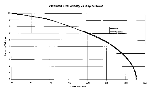
Fig.6 shows the predicted sled velocity.
Detailed Description of Preferred Embodiments
In a preferred embodiment of the invention, software operating in accordance
with the principles of the invention is incorporated into MSC.Dytran (trade
mark)
2004 fmite element analysis package which is available from MSC.Software Inc.
This known software can be programmed with failure stress values for composite
materials and thus for a given finite element of the material can attempt to
model the
forces on that element until the stress it experiences exceeds the failure
stress
whereupon the element is deleted. However, in the embodiment of the invention
now being described, this part of the functionality of the software is
supplemented.
Instead, the process shown in Fig. 1 is followed.
CA 02572704 2007-01-02
WO 2006/003438 PCT/GB2005/002627
11
In this process, it is first determined, at 2, when there is impact between
the
defined impactor and an element selected as being capable of crush of the
structure.
If there is contact, it is determined, at 4, whether any of the nodes of the
element
have penetrated the impactor. If none of the nodes has penetrated the
impactor, the
software moves to the next main step at 6 in which the element stress is
updated.
However, if penetration is detected, the software moves, at 7, to assess
whether the
element connected to the node is already tagged as undergoing crush. If it is
not, the
software adds this tag to the node at 8 and then moves on to update the
element
stress at 6. If the element connected to the node had already been tagged as
undergoing crush though, a further series of sub-routines is carried out first
at 9.
Firstly the contact force is set to zero. Secondly the direction of crush is
stored and
lastly the relative velocity is stored.
The next main step at 6 is to update the stress on the element. To do this it
is
determined, at 10, how many of the nodes of the element have been tagged as
undergoing crush. If all of the nodes of the element have been tagged, the
element is
taken to have failed and is therefore removed from further calculations at 12.
If one
or more, but not all of the nodes is tagged, the software, at 14, projects the
crushing
direction in the element co-ordinate system to allow determination of the
correct
direction for material properties to be calculated. It then determines the
resistance
stress of the element from input data (explained in greater detail below with
reference to Fig. 2) and the whole element is tagged as undergoing crush.
Alternatively, if at the assessment step 10 none of the nodes is tagged as
undergoing crush, the system simply does nothing, at 16. Whichever of the
possibilities 12,14,16 is encountered, the software then moves to 23 where the
conventional finite element stress update is undertaken prior to moving on to
the
third main step of the process in which crushing contact is calculated, at 18.
In this stage, a determination is made, at 20, as to whether the element has
been tagged as undergoing crush. If the element has not been tagged,
processing
continues within the previous conventional analysis mode before returning to
the
beginning of the process shown in Fig. 1.
However, if the element has been tagged, four actions are taken. Firstly, the
intersection between the element and the impactor is calculated. The
intersection is
CA 02572704 2007-01-02
WO 2006/003438 PCT/GB2005/002627
12
calculated to determine the amount of material being crushed. If a triangle is
crushed from a vertex, the material being crushed will increase and, as a
result, the
resistive force will increase as the element is consumed through the barrier.
Secondly, the crush direction is obtained, thirdly the crush stress is
obtained and
fmally the crush forces are calculated. Thereafter, processing continues
within the
previous conventional analysis mode before returning to the beginning of the
process shown in Fig. 1.
In order to calculate the predetermined resistance to be fed into the model
described above, a small coupon of the relevant composite material is
subjected to a
crush test. In one example, material sections of 60 x 30 mm are cut from flat
plates
and bonded to a 50 mm thick honeycomb sandwich in order to promote stabilized
crush. The outer edges of each skin presented to the impactor are chamfered at
approximately 60 to present a sharp edge to minimize the spike in crush
resistance
exhibited at the start of crushing and thereby minimize the risk of
delamination from
the honeycomb at the start of crushing where the initial failure corresponds
to the
compressive failure performance of the element. The honeycomb cells are
oriented
perpendicular to the direction of coupon crush and therefore do not absorb
significant energy but ensure that the skins do not buckle. A typical plot of
resistance force exhibited by a coupon versus deflection (i.e. the amount of
the
coupon which has been crushed) is shown in Fig. 2. From this it will be seen
that
throughout most of the range of deflection the force is relatively constant.
By taking
a suitable average value for this, the resista.n.ce force to be used in the
analysis model
for a particular material may be determined. Since the coupon has a constant
cross-
sectional area, there is no variation of the resistance force with contact
area.
However in the model the actual value of the resistance force is calculated as
directly proportional to the contact length.
It will be appreciated that this method of coupon testing provides a low cost
way of determining the stabilized crush properties for a wide variety of lay-
ups
configurations and angles. Thus typically such tests would be conducted for
each of
the material constructions used in the structure to be modelled as crush
capable, and
optionally each at a range of angles.
In an exemplary application of the embodiment described, a
CA 02572704 2007-01-02
WO 2006/003438 PCT/GB2005/002627
13
rectangular-section cone structure of a T300 carbon fibre composite material
approximately 85 x 115 mm in section and approximately 455 mm long was
mounted on a rigid barrier and a rigid sled is propelled at a controlled
velocity into the cone. Fig. 3 shows the measured deceleration of the
trolley versus displacement filtered using a Butterworth Order4 low pass
filter with upper cut-off frequency of 300Hz in this experiment (impact
occurring at Displacement=0). From this the actual resistance force
encountered may be calculated simply from the deceleration of the trolley
and its mass. Fig.4 shows the sled velocity versus displacement for the same
experiment.
The cone was modelled using Dytran 2004 software modified as described
above with reference to Fig. 1. The predicted deceleration profile is shown in
Fig.5. filtered in the same manner as the test results, using a Butterworth
Order4 low pass filter with upper cut-off frequency of 300Hz. From this it
will be seen that the profiles and absolute values of the deceleration are
similar. Fig.6 shows the predicted sled velocity and here a remarkable
similarity exists between the tested and predicted results. For example,
the prediction of the distance taken to bring the trolley to a rest was
predicted at 327mm and was measured at 328mm meaning that the prediction was
accurate to within 1% percent. This is much more accurate than could be
achieved with the prior art methods.