Note: Descriptions are shown in the official language in which they were submitted.
CA 02572711 2009-06-26
COMPOSITE SIDING USING A SHAPE
MOLDED FOAM BACKING MEMBER
BACKGROUND
[0002] The present invention pertains to sidewall foam backer panels to be
used as siding
elements attached to elongated siding panels having a vinyl or other polymeric
veneer profile for an
exterior wall of a building.
[0003] The construction industry, both new construction and remodeling
presents
opportunities for the use of composite siding panels having a veneer of a
vinyl or other suitable
decorative polymeric material connected to foam insulating backers. Such
materials can be
generally referred to as insulated siding.
[0004] Typically, the insulated foam backer is prepared by the initial
formation of the
polymeric foam by placing suitable polymeric material in a suitable expander
machine where
precursor resin is transformed from its granular state to pellets in an
expanded state. The expanded
pellets are conveyed to a suitable molding machine where they are subjected to
heat and steam
pressure to create a block, typically 50 x 50 x 216 inches. The block is cut
to a desired profile using
a computer-controlled hot wire cutting machine. A suitable number of
beadsllines of permanently
flexible adhesive are applied to the prepared insulated foam backer and a
vinyl siding product
having a matching profile is adhered to the prepared foam insulation backer.
To date, the most
efficacious adhesive materials are hot-melt type adhesives.
[0005] The overall "block molding" method and resulting product are not
without problems.
It has been found that hot-wire cutting operations performed on the foam block
in order to provide
the desired insulated foam backer profile also relieve stresses and introduce
camber into the
material cut from the sides of the foam block. As used herein, the term
"camber" de cribes the
problem of the insulated foam backer material exhibiting lateral bow. This
problem can arise
because the block of expanded foam polymeric material has various densities
and moisture
gradients throughout its profile. Cutting the foam block material can release
stresses resulting in the
CA 02572711 2007-01-02
outside panels being cambered. The significance and intensity of the problem
can increase
depending upon the length and/or width of the foam block and the resulting
composite siding
product. It can be appreciated that siding products of greater length and
width are desirable for ease
and efficiency in installation in various construction projects. It should be
noted that backers
exhibiting camber frequently jam in the factory lamination equipment making it
difficult to align
and bond the respective materials. Backers having camber measured from side
edge to side edge of
more than 1/2 inch per piece over the length of a piece are typically
scrapped.
[0006] Additionally, the surface profiling operation presents its own problems
and
drawbacks. The hot wire cutting equipment is limited to two (2) dimensional
cutting. Heretofore,
the blocks of expanded foam were formed and hot wire cut to provide the
desired shape or contour.
Additionally, any side or interior surface contour must be imparted by
suitable processes that, many
times, are implemented separate from the initial foam formation and foam
backer formation
process.
[0007] It can be appreciated that additional handling necessary for the
formation of
geometric regions and features can increase the complexity of the
manufacturing process and can
increase the opportunity for damage and the like. The cutting processes
previously necessary to
produce the contoured insulated foam backer panel can result in a backer panel
having undesirable
wire marks and roughed surfaces. Such rough surfaces can contribute to
unsightly, irregular siding
appearance, increased handling and processing, less breakage. Additionally,
the roughened surface
can have adverse effects on the effectiveness of adhesives and the appearance
of any materials
overlying the surface.
[0008] Thus, it would be desirable to provide an insulated siding construction
suitable for
use in outdoor applications such as homes and the like that utilizes a three
(3) dimensional shape
molded insulated foam backer. The EPS foam backer material is the most likely
material for this
use. However, other materials may not be suitable to shape molding.
SUMMARY
[0009] Disclosed herein is a unique shape molded foam backer panel designed
and molded
to provide a superior foam backer that will support and insulate a 12 %2 feet
siding panel. The
backing member also includes a rear face and an opposed front face and is
composed of closed cell
expanded polymeric shape-molded foam. The front and rear faces are composed of
closed
2
CA 02572711 2009-06-26
polymeric cells. The backing member is configured with at least one three
dimensional
feature such as front face geometric features, rear face geometric features
and vertically
oriented side features.
[009a] Accordingly, in one aspect there is provided a panel for mounting on a
wall
comprising:
a shape-molded backing member; and
a siding member attached to the backing member;
wherein the shape-molded backing member includes a rear face and an
opposed front face and is composed of closed cell expanded polystyrene foam,
the front and
rear faces of the shape-molded backing member having an outer surface composed
of a tough
smooth skin and the shape-molded backing member is camber free and the
dimensions of the
shape-molded backing member are stable and predictable.
3
CA 02572711 2009-06-26
DESCRIPTION OF THE DRAWINGS
[0010] The description makes reference to the accompanying drawings wherein
like
reference numerals refer to like reference characters throughout the several
views and in
which:
[0011] Fig. 1 is an exploded view of an insulated siding unit having a shape
molded
insulated foam backing member as disclosed herein;
[0012] Fig. 2 is a cross-sectional detail of abutting insulated siding panels
of Fig. 1;
[0013] Fig. 3 is a cross-section of two interlocking composite backers
positioned in
top to bottom abutting relationship;
[0014] Fig. 4A is a detail cross-sectional view of two abutting side edges of
insulated
foam backer units. The vinyl panels show the unique new siding panel overlap
and
indentation feature of Fig. 1;
[0015] Fig. 4B is an alternate version of Fig. 4A;
[0016] Fig. 5 is a cross-sectional view of a portion of the insulated siding
panel
element of FIG. 1 shown in place on a wall;
[0017] Fig. 6 is a detail cross sectional view of the insulated foam backer
and the
composite insulated siding panel;
[0018] Fig. 7 is a cross-sectional of top-to-bottom abutting insulated foam
backer
panels with the corresponding siding panels assembled and shown mounted on a
wall;
[0019] Fig. 8 is a front elevational view of a portion of a shape molded foam
insulated
siding backer panel;
[0020] Fig. 9 is a detail front elevational view of a portion of the panel of
Fig. 8;
[0021] Fig. 10 is a front elevational view of the backer member of the
composite
insulated siding panel of Fig. 8 with the siding layer removed;
[0022] Fig. 11 is a detail front elevational of the upper portion of the
backer member
of Fig. 10;
[0023] Fig. 12 is a detail elevational view of the side portion of the backer
member of
Fig. 10;
[0024] Fig. 13 is an elevational view of a back portion of the backer member
of Fig.
10;
3a
CA 02572711 2007-01-02
,. .
[0025] Fig. 14 is a detail elevational view of the bottom portion of the
insulated siding panel
of Fig. 13;
[0026] Fig. 15 is a view of a cross-sectional cut through the backer panel
portion of Fig. 8;
[0027] Fig. 16 is a side view of the insulated siding panel of Fig. 8;
[0028] Fig. 17 is a front elevational view of portions of two abutting
insulated siding
panels;
[0029] Fig. 18 is a side view of the abutting side panels in Fig. 17;
[0030] Fig. 19 is an elevational view of the abutting panels of Fig. 17 with
one siding layer
removed;
[0031] Fig. 20 is a detail elevational view of Fig. 19 taken at the central
portion;
[0032] Fig. 21 is a detail elevational view of Fig. 19 taken at the top
central portion;
[0033] Fig. 22 is an elevational view of the back portion of the abutting
panels of Fig. 19;
[0034] Fig. 23 is an end view of the abutting panels of Fig. 19 showing the
bottom rear
portion thereof;
[0035] Fig. 24 is an elevational view showing a bottom detail of the two
abutting insulated
siding panels of Fig. 17; and
[0036] Fig. 25A and 25B are side detail views of two panels abutting top to
bottom with one
another.
DESCRIPTION
[0037] Referring to Figs. 1-7, disclosed herein is an insulated foam backer
panel 10 having
shape molded foam backing member 14 and a siding layer 12. The shape molded
foam backer
member 14 has a front face 16 and a rear face 18 opposed thereto. At least a
portion of the front
face 16 of the backer member 14 is covered by the siding layer 12. The shape
molded backer
member 14 will also have an opposed side face, such as side face 20 as well as
top face 22 and
bottom face 24. Embodiments of the insulated siding panel 10 as disclosed
herein are depicted in
Fig. 1.
[0038] The backer member 14 is composed of expanded polymeric foam with the
front and
rear faces 16, 18 composed of a substantial portion of closed polymeric cells.
As used herein the
term "substantial portion of closed polymeric cells" is taken to mean that a
portion of polymeric
cells that will provide a smooth surface such as that illustrated in Fig. 5.
The cells proximate to the
4
CA 02572711 2007-01-02
surface may be compressed or elongated as compared to cells located in the
central region of the
backer member 14. In contrast, other backer members typically have at least
one face 16, 18 that is
characterized by ruptured cells or cell structure as illustrated in Fig. 6.
The typical surface of other
wire cut backer members will have multiple regions of concavity imparted
during the cutting
process contributing to the overall roughness of the respective face. Where
desired or required, at
least one of the top face 22, bottom face 24 and the side face(s) 20 can
possess the smooth surface
characteristics present in the front and rear faces 16, 18.
[0039] It is contemplated that various cellular plastics can be employed as
the material for
the shape molded backing member or foam insulated backer disclosed herein. As
used herein, the
term(s) "cellular foam" or "cellular foam plastic" are taken to mean a plastic
or polymeric material
with numerous cells of trapped air distributed throughout its mass. Suitable
examples of such
materials can also be referred to as expanded plastics or foamed plastics with
expanded polystyrene
foam being but one non-limiting example.
[0040] "Expanded polystyrene foam" as used herein refers to cellular foam
plastic made
from polystyrene typically by incorporation of a volatile blowing agent into
polystyrene beads as
they are polymerized or afterward. In expanded polystyrene, beads of
polystyrene are first pre-
expanded and allowed to rest for a suitable interval, then molded in closed
steam-heated shaped
molds to produce closed-cell molded foams. The size and density of the closed
cells can vary from
application to application.
[0041] As used herein, the term "shape molded backer member" is taken to mean
a member
formed of front and rear faces 16, 18 with surfaces characterized by a
substantial portion of closed
polymeric cells. The term "closed polymeric cells" as used herein is taken to
mean intact units
resulting from the expansion and foaming process. It is contemplated that
these materials may be
spheroid nodules having a polymeric shell with a relatively hollow central
cavity. The front and
rear faces 16, 18 are composed of a substantial portion of intact cells, i.e.,
cells that do not have
their inner cavities exposed. Where desired or required, the shape molded
backer member may
have additional edges 20, top and/or bottom ends 22, 24. It is also
contemplated that various
contours, grooves and details can be defined in the one or more of the faces,
edges or ends. These
can be characterized in whole or in part by the smooth, tough surface of the
front and rear faces.
[0042] The shape molded backer member 14 has a tough, durable, smooth skin on
the outer
surface of the front and rear faces 16, 18, as well as any ends, edges, and
additional surfaces. The
CA 02572711 2007-01-02
PATENT
unique surface characteristics of the shape molded product can permit and
facilitate use with siding
layers having reduced veneer thickness. Without being bound to any theory, it
is believed that the
outer skin of the shape molded backer member underlies the thin siding layer
and acts in concert
with the structure of the backer member to support and conform the veneer in a
smooth,
aesthetically pleasing configuration. It is contemplated that the siding layer
may be traditional vinyl
veneer material at thickness measuring from .020 to .036". The current
standard vinyl siding
veneers are made to bottom/low thickness at .040". Various other polymeric or
coating materials as
would be cost effective can be used.
[0043] Thus, the term "shape molded" pertains to closed cell foam panels
formed by the
reaction of materials such as expanded polystyrene in a suitably configured
die mold. Typically the
precursor material is reacted in the presence of water and heat to expand
pellets of the polymeric
precursor material during the reaction process. During the process that forms
the panel, the closed-
cell material expands and presses against the die surface to form compressed
elongated closed cells
that form a characteristic tough smooth skin. The shape molded process
produces a panel that is
essentially straight and free of camber. It is contemplated that the shape
molded panel member will
be self-supporting. Without being bound to any theory, it is believed that the
shape molding
process can position expanded foam of varying density at specific locations
throughout the shape
molded panel. The variations in density can provide a tough, durable,
reinforced insulated foam
panel member that resists warping, bowing and handling damage. It is
contemplated that the
backing member 14 can be configured to provide structural integrity and
support to the resulting
insulated siding panel 10, through "dual" densities; and the dimensions of the
backing member 14
are stable and predictable providing a superior quality.
[0044] The backing member 14 can have various three-dimensional features
located on one
or more of the front face 16, rear face 18, top end 22 or bottom end 24 as
would be suitable for the
associated insulated siding panel 10. The three-dimensional features can
include but are not limited
to ridges, grooves, indents, detents and the like. Such geometric features can
be imparted in a single
operation by the shape molding process. The backing member 14 is pigmented as
desired or
required. In situations where the siding layer 12 is extremely thin, it is
contemplated that the
insulated foam backing layer can be pigmented to complement the color of
extremely thin siding
layers.
6
CA 02572711 2007-01-02
[0045] The siding layer 12 as disclosed herein can be a siding product adapted
to overlie at
least a portion of the front face 16 of the shape molded backing member 14.
The siding layer can
have any suitable configuration or contour suitable for the given panel
application. It is also
contemplated that the siding layer 12 may have any suitable configuration
desired or required to
impart the aesthetic look desired. One non-limiting example of aesthetic
configuration would be
contours configured to mimic traditional flat faced wooden clapboard.
[0046] It is contemplated that the shape molded backing member 14 can have a
suitable
configuration complementary to the configuration of the siding layer 12.
Suitable configurations
are depicted in the various drawing figures. The degree of correspondence
between the contours in
the siding layer 12 and shape molded backing layer 14 can be at any degree
from approximate to
exact depending on various factors including but not limited to the material
type and/or thickness of
the siding layer 12. The shape molding process provides dimensional accuracy
and consistency that
is far greater than that achieved through the wire cutting process.
[0047] In the insulated siding panel 10 disclosed herein, it is contemplated
that the siding
layer 12 will be composed of a suitable polymeric material with vinyl
materials being particularly
suitable. The siding layer 12 can have any suitable thickness. While it is
contemplated that siding
thicknesses above 0.037 to 0.039 inches may be employed as desired or
required, the shape molded
backing member 14 as disclosed herein is particularly suited for use in an
insulated siding panel 10
having a polymeric siding layer of a thickness below that heretofore necessary
for providing
structural support for the insulated siding panel 10. Polymeric materials,
particularly vinyl
materials are contemplated for use in the insulated siding panel 10 disclosed
herein. In various
embodiments, it is contemplated that the thickness of the siding layer cari be
below 0.040 inches. It
is contemplated that, in such situations, the structural strength of the
insulated foam backing layer
14 is such that the need for structural strength and integrity of the siding
layer 12 is minimized.
[0048) Is contemplated the insulated siding panel 10 will have at least one
ridge 26 defined
in the front face of the pane and extending form one side to another. The
panel 10 may also include
suitable lateral indentations and planar regions can also be included in the
outer face of the panel.
[0049] The siding layer 12 can be connected to the backing member 14 in a wide
variety of
fashions. It is contemplated that connection can occur at any time between
manufacture and
installation such that the siding layer 12 and backing member 14 are joined to
one another in the
installed or "in use" configuration. Nonlimiting examples of "connection"
include insertion or
7
CA 02572711 2007-01-02
"dropping in" the backing member 14 between the siding layer 12 and the wall
as well as
procedures such as the use of mechanical fasteners, adhesive bonding, and/or
chemical bonding at
any location either prior to or during installation. The methods can be mixed
as desired or required.
[0050] Where adhesive materials are to be employed, the adhesive can be
applied by any
suitable method. The adhesive material can be applied as a bead, thin layer or
the like. In certain
applications, it is contemplated that the adhesive can be applied by a
suitable spray applicator to
provide a thin uniform adhesive coating over the tough durable skin of the
backing member. The
shape molded backer has a smooth surface finish that fits snuggly with the
siding panel, therefore
adhesive mileage is greater and adhesive quantities can be reduced while the
resulting bond is
stronger. Suitable materials will be continuously flexible non-latex adhesives
such as thermoplastic
PSAs. Non-limiting examples of suitable spray thermoplastic adhesive coating
materials include
DUROTAK.
[0051] As depicted in Fig. 1, the shape molded backing member 14 has a front
face 16 that
includes centrally positioned lateral ridge 26. The upper face can include
other contours and
regions as desired or required to conform to the general surface contours
required in the insulated
siding panel 10. The shape molded backing member 14 has a central depressed
region 28 extending
downward from the centrally positioned ridge 26. The depressed region is
contiguously connected
to an outwardly extending region 30. The outwardly extending region 30 is
contiguously joined to a
planar region 32. Together the centrally positioned ridge 26, the central
depressed region 28,
angled region 30 and the planar region 32 form a contour that mimics the
contours found in a single
conventional siding panel.
[0052] It is contemplated that the shape molded backing member can be
configured with
multiple contours to mimic multiple conventional siding panels as desired or
required. In the
embodiment as depicted in Fig. 1, the shape molded backing member 14 is
configured to mimic two
conventional siding panels. The various regions can each be characterized by
the closed cell
polymeric surface and by the tough smooth skin described previously. The
smooth surface typically
extends through each of the various planar regions, however, where desired or
required, it is
contemplated that one or more regions can have differing surface
characteristics provided that the
overall performance of the backing member is not compromised.
[0053] The shape molded backing member 14 can also have side regions 20 and/or
top and
bottom regions 22, 24 that include surfaces formed of expanded foam material.
As depicted in
8
CA 02572711 2007-01-02
Fig. 1, the shape molded backing member 14 is formed with a detent or pocket
extending vertically
along one side of the shape molded backing member 14. As depicted, the detent
34 extends
vertically inward from one of the side faces 20. The detent 34 is contiguous
with the outer face 16
of the shape molded backing member 14. The detent 34 has outwardly positioned
surfaces that are
composed substantially of closed cell polymeric foam. The surface includes the
tough smooth skin
found in the outer face 16. As depicted, the siding layer 12 of insulated
panel 10 overlays the outer
surface 16 of shape molded backing member 14. The siding layer 14 overlies the
detent 34 to form
a continuous pocket as depicted in Fig. 1 and 2. As depicted, the detent 34
has an offset outwardly
oriented face 36 and a side wall 38 that is contiguously connected to the
outer face 16 at an outer
edge. The shape molded backing member 14 will have a first average thickness
T1 in the central
region of the backing member that is sufficient to provide suitable insulation
and support qualities
to the finished insulated panel 10. The shape molded backing member 14 can
have a second lesser
thickness T2 such that the detent 34 is configured to accommodate a projection
or projections
extending from an abutting insulated panel. The detent 34 provides a pocket
for receiving
protruding siding layer for an abutting insulated siding panel. In this
manner, It is contemplated
that the detent 34 will be toleranced to securely receive the abutting
insulated side panel. Suitable
detents can be configured in the shape molding process to impart the desired
detent configuration.
100541 The opposed side region 20a can be configured without the detent 34
such that the
outer face 16 uniformly terminates at the side edge 20a. Where desired or
required, the portion of
the siding layer 12 proximate to the opposed side region 20a can project
outward beyond the
opposed side region 20 and be received in the channel defined by a detent 34
and overlying siding
layer 12 of an adjacent insulated siding panel 10.
[0055] The side edges 20, 20a may have a surface characterized by closed
polymeric cells.
It is contemplated that the surface of edge(s) 20, 20a will exhibit a tough,
durable, smooth skin,
consistent with the surfaces of the front and rear faces. The detents can have
various attributes and
configurations imparted by the shape-molding process. As depicted in Fig. 2,
edges 20, 20a can be
placed in abutting or adjacent position as desired or required. The placement
of and space between
edge 20 relative to mating edge 20a will be that appropriate to prevent or
minimize air infiltration.
The mating configuration also serves to lessen the effect of peel away of
installed insulated siding
during wind and weather and provides greater continuity - both visual and
structural -- of the siding
9
CA 02572711 2007-01-02
product in the installed configuration. The height of the detent 34 will
typically be sufficient to
receive the protruding portion the siding layer of the abutting or mating
insulated siding panel.
[0056] It is contemplated that the surface of detent 34 will have a tough,
durable, smooth
skin on its outer surface essentially contiguous with that of the side face
20. The detent 34 can be
configured as desired or required. Non-limiting examples of such additional
geometric constructs
include various tongue and groove elements to interconnect two abutting
insulated siding panels as
depicted in Fig. 1, it is contemplated that the detent 34 extends from the top
of the shape molded
backing member or from a region proximate thereto to the bottom of shape
molded member or to a
region proximate thereto. Thus between panel-to-panel interconnection
utilizing panels with mating
side configurations as depicted herein provides an extended siding
construction that minimizes air
infiltration and can present a visually continuous surface with minimal
perceptible vertical ridges,
lines and contours. This is a very desirable installation and marketing
feature.
[0057] It is also contemplated that the regions proximate to side faces 20,
20a of shape
molded backing member 12 of insulated siding panel 10 can have additional
geometric
configurations as desired or required. Non-limiting examples of such
additional geometric
constructs include various tongue and groove elements to interconnect two
abutting insulated siding
panels. The region proximate to the side edges 20, 20a can be configured with
various suitable
geometric features to facilitate installation, position of the insulated
siding panel 10 relative to other
siding panels and/or other architectural features or elements as desired or
required. Non-limiting
examples of such enhancements can include various mating protrusions,
indentations, and the like,
as desired or required. It is contemplated that such geometric enhancements
may be ones that
facilitate positioning of one panel relative to another during or after
installation. It is also
contemplated that such geometric enhancements may be ones that provide
attributes such as
identification, instruction, or the like, as desired or required.
[0058] It is also contemplated that the shape molded backing member 14 can
have upper
and lower edges 22, 24 having suitable configurations as desired or required.
As depicted in Fig. 1,
the upper edge 22 of shape molded backing member 14 is located proximate to
upper region 36. As
depicted, upper region 36 has a lip 38 that extends outward from the shape
molded member 14
defining edge 40. In the insulated siding panel 10 as disclosed herein, the
upper edge 40 of siding
layer 12 is in abutting relationship to edge 42. The edge 40 may have any
suitable depth. As
CA 02572711 2007-01-02
depicted, it is contemplated that the depth of edge 40 will be one sufficient
to permit the upper
edge 42 of siding layer 12 to be seated flush with face 38 of upper region 36.
[0059] As depicted, the siding layer 12 projects beyond the front face 16 of
the insulated
siding panel 10 to define an opening into which a siding layer 12 of a mating
insulated siding panel
element can project. When installed, the respective panels are interlocked in
a shiplap fashion.
[0060] Side face 38 and/or edge 40 can have surfaces composed of closed cell
polymeric
material. Thus side face 38 and/or edge 40 can have the tough smooth surface
discussed previously.
[0061] If desired or required, the lower edge 24 can have a region proximate
thereto that
includes the lower portion of flat region 32 as depicted in Fig. 3. The lower
region can include a
lateral relief 44 defined on the inner face 18 of the shape-molded backing
member 14. The lateral
relief 44 is configured to overlay the region proximate to the upper edge 22
of a mating shape-
molded backing member 14. It is contemplated that the surfaces defining the
detent 44 can be
composed of closed cell polymeric foam and may have the tough smooth skin
discussed previously.
[0062] Where an elongated channel is provided as lateral relief 44, it is
contemplated that
the lateral relief 44 will have dimensions sufficient to accommodate expansion
and minimal
movement of the insulated siding panels relative to one another while
maintaining imperviousness
to wind penetration. The panel-over-panel configurations utilizing panels with
mating top and
bottom configurations as depicted herein provides siding construction that
minimizes air infiltration
while providing an aesthetically pleasing visually continuous surface.
[0063] It is contemplated that an end fonn can include other shapes and
configurations as
desired or required. At least a portion of the contours and configurations
will be characterized by
closed cell polymeric material. The contours and configurations will have a
tough smooth skin
surface similar to that found on the inner and outer faces of the shape molded
backing member 14.
While it is contemplated that at least a portion of the contours and
configurations will be
characterized by closed cell polymeric surfaces, it is within the purview of
the present disclosure
that all contours and configurations are characterized by closed cell
polymeric foam surfaces.
[0064] The shape molded backing member 14 as disclosed herein is straight and
free of
camber. As used herein, the term "camber free" is defined as a shape-molded
backing member
having a camber of less than 1/2 inch.
[0065] Without being bound to any theory it is believed that the shape molding
process
provides a self-contained structure that balances internal stresses produced
during the foam
11
CA 02572711 2007-01-02
formation process. It can be appreciated that the shape-molded panel produced
by producing
expanded foam in a suitably configured die, produces a thin panel having the
geometric
configurations integrally included in the molded panel. The self-supporting
nature of the shape
molded backing member provides an insulated siding panel that is straight and
free of camber. The
backing member and the insulted siding panel can have lengths greater than 16
feet and thicknesses
between'/4 and 12 inches. Without being bound to any theory, it is believed
that the shape molded
backing member resulting from the production of expanded foam material in the
associated die that
is durable, and can be more readily and easily aligned in the manufacturing
and assembly processes
of the insulated siding panel. One benefit of this is less scrap and increased
production rates.
Another benefit is that the backing member is capable of taking more of the
structural support load
of the resulting insulated siding panel.
[0066] The shape molded backing member 14 disclosed herein exhibits greater
flexural
strength than backer members produced by the wire cut methods. It is believed
that the smooth
tough polymeric skin formed during the shape molding process works in concert
with the superior
fusion strength derived from the molding process to provide significantly
greater flexural strength.
It is believed that the flexural strength of shape molded backing members as
disclosed herein can be
increased by as much as 20 percent over similarly configured parts prepared by
wire cut methods.
[0067] To this end, flex tests are conducted on two similarly dimensioned
backing members
formed by either the wire cut method or by shape molding. Flex tests conducted
in accordance with
ASTM C203 confirms that the shape-molded backing members possess greater
flexural strength in
excess of 20 percent over wire cut counterparts with flexural strengths
greater than 24 percent being
achievable.
[0068] Shape-molded backing members such as those disclosed herein exhibit
less
brittleness than wire cut backer members. Shape molded backing members as
disclosed herein can
advantageously exhibit more resistance to many of the cracking and breakage
events typically
encountered during storage, handling and installation.
[0069] Shape molded backer members as disclosed herein can also exhibit
greater bridging
strength over wire-cut backing members. Insulated siding panels 10 utilizing
shape-molded backing
members 14 will typically exhibit greater capability of spanning larger gaps
in the wall surface
thereby leveling the exterior wall. It is also contemplated that shape molded
backer members can
12
CA 02572711 2007-01-02
be used in insulated siding panels utilizing reduced thickness siding elements
such as those below
0.040 inches.
[0070] Surfaces of shape molded backing members typically will be free of
cellular craters
and linear depressions, marks, and artifacts such as those created by wire
cuts. The shape molding
process produces a finished part with excellent dimensional stability. Shape
molded backing
members will exhibit a tough smooth surface having compressed closed polymeric
cells.
[00711 Thus as broadly construed, the shape molded backing member 14 has front
and rear
faces characterized by a substantial portion of closed polymeric cells. It is
contemplated that the
portion of closed polymeric cells present in the front face and the rear face
will be that capable of
providing a suitably continuous smooth surface. The degree of smoothness can
be measured by a
profilometer or any suitable measuring means that will facilitate stronger
bonding with an
associated siding layer.
[0072] Backing member 14 has a rear face 18 and an opposed front face 16. The
rear face
of the backing member 14 defines a planar surface adapted to overly a wall or
suitable surface on
which the insulated siding panel 10 is to be positioned.
[0073] The insulated siding element 10 also includes siding layer 12 adapted
to overlay and
be connected to the backing member 14. As depicted, the siding layer 12 is
connected to the
backing member 14 such that at least a portion of the front face 16 of the
backing member 14 is
covered by the siding layer.
[0074] The siding layer 12 can be connected to the backing member 14 to any
suitable
means. As depicted, the backing member 14 can be connected to the siding
member 12 to a suitable
bonding or adhesive layer 48 interposed between the two respective layers. It
is contemplated that
the adhesive layer is composed of a suitable material such as a polymeric
adhesive compound or
formula. The adhesive material is applied at a sufficient thickness to
facilitate adhesion between the
respective backing member 14 and siding layer 12 at predetermined or
prescribed bond strength.
[0075] The adhesive layer 48 will have an outer surface opposed to the backing
member 14.
The inner surface of the adhesive layer contacts and conforms to the surface
of the outer face 16 of
the backing member 14. The adhesive or bonding layer 48 overlies and conforms
to the smooth
surface defined by the closed cells of the polymeric material.
[00761 The adhesive material can be any suitable composition compatible with
the material
employed in the backing member 14 and that employed in the siding layer 12.
The material of
13
CA 02572711 2007-01-02
choice will be one that maintains flexibility and strength in concert with the
siding layer and
backing member 14 over a wide variety of temperatures. One non-limiting
example of a suitable
temperature range is -20 F. to 220 F.
[0077] It is contemplated that the adhesive layer can be produced by any
suitable manner or
process. A non-limiting example of an adhesive layer producing process is by
extrusion or spray
processes. When these adhesives are employed, it is contemplated the materials
will be a suitable
continuously flexible adhesive. Suitable materials include thermoplastic
polymeric pressure
sensitive adhesive. Non-limiting examples of such materials include water
based or solvent based
PSAs containing acrylic, vinyl acrylic, styrene acrylic, and urethane acrylic
and butyl acrylate. Peel
adhesion, tack level, creep and shear resistance, viscosity, age resistance,
crosslinking, hardness,
and softness can be adjusted to a desired end point by selecting the
appropriate additives. Suitable
materials include those commercially available from National Starch under the
trade name
DUROTAK.
[0078] Deposition of the adhesive material can be by any suitable method with
methods that
reduce or eliminate telegraphing through the overlying siding layer being
preferred. Thus spray
deposition can be utilized as well as methods such as extrusion, roller
coating, curtain coating and
the like.
100791 It has been found quite unexpectedly that the adhesive qualities of the
bonding
material are enhanced when a shape molded backing member 14 having the
aforementioned smooth
surface structure is employed. Without being bound to any theory, it is
believed that the smooth
surface structure of the backing member disclosed herein provides a suitably
uniform bonding
surface that permits a continuous cross-sectional bond throughout the surface
region of the backing
member 14 and the interior surface of the siding layer 12 with minimized
quantities of adhesive,
thereby achieving greater bonding area with superior bond strength while
potentially reducing
adhesive quantities employed. In contrast, backing members formed by wire
cutting methods
exhibit surfaces with large numbers of open cells. The uneven surface
topography presents
challenges in achieving uniform adhesive deposition. Generally thicker and
possibly localized
adhesive coatings are necessary to achieve a suitable bonding layer between
the siding layer and the
backing member. Without being bound to any theory, it is believed that shape
molding process in
which the polymeric material is expanded in a die mold produces a surface
particularly suited to the
application of adhesive material. The surface of the shape molded backing
member is characterized
14
CA 02572711 2007-01-02
by compressed closed cell polymeric material that provides a tough smooth
surface to which the
adhesive can be applied and adhered.
[0080] It is contemplated that the siding layer 12 can be composed of any
suitable sheet or
film stock material. Materials of choice typically will be materials resistant
to extremes in the
external environment over the life of the insulating siding panel 10. Non-
limiting examples of
environmental challenges include extremes in temperature, prolonged exposure
to ultraviolet light
and/or certain levels of impact and vibrational challenges due to wind and the
like.
[0081] The siding layer 12 may be composed of any suitable polymeric, or
cementious
material. It is contemplated that the siding material will be one capable of
providing suitable
environmental resistance and durability. The material of choice may be
suitable vinyl materials as
well as materials such as fiber cement.
[0082] The material employed in the siding layer 14 may have sufficient
thickness to
maintain its shape and contour throughout the useful life of the insulated
siding element 10 when
the siding layer 12 is integrated with a suitable backing member 14. It is
contemplated that the
siding layer 12 can be suitably contoured to conform to the contours of the
shape-molded backing
member 14. While the correspondence between the respective contours can be
exact, if desired or
required, it is contemplated that the contours in the respective elements can
vary depending upon
the nature of the end product.
[0083] Suitable polymeric materials for use in the siding layer 12 can
include, but are not
limited to, thermoplastic and/or thermosetting materials of which various
grades of vinyl are an
example of but one suitable class. Other examples of suitable film or sheet
stock material include
various extruded ionmeric films, polyethylene based films and the like. It is
contemplated that the
siding layer can be formed of geometrically self-supporting materials.
Alternately, it is
contemplated that the siding layer 12 can be formed of materials that derive
their support, at least in
part, from the underlying shape-molded backing member 14.
[0084] While it is contemplated that the siding layer 12 can be self
supporting, it is believed
that the shape molded backing member 14 having the tough, smooth outer surface
can provide
sufficient support for the siding layer 12. Thus it is contemplated that the
siding layer 12 can be
prepared from a reduced thickness vinyl material such as materials below 0.04
inches. Alternately,
the material may be a flexible polymeric film material that derives its shape
and contour from the
underlying shape molded backing member 14.
CA 02572711 2007-01-02
[0085] The degree to which a polymeric film or layer material is flexible and
derives its
support from the shape molded backing member 14 is determined, at least in
part by the impact
resistance requirements of the finished insulated siding elements 10. As used
herein, the term
"impact resistance" is taken to mean the ability of the siding layer to resist
or withstand tearing or
breakage due to impact of an object with the siding element. The shape molded
backing member
disclosed herein has been found, unexpectedly, to increase impact resistance
of resulting siding
layer by 3 times or greater. Thus the backing member configuration disclosed
herein can permit
reduction in the gauge of the siding layer to reduce costs without
compromising performance and
durability of the finished product.
[0086] One non-limiting example of suitable characteristics for domestic homes
is that the
insulated siding element 10 will have an impact resistance of at least 160
inch/pounds as measured
by industry standard ASTM D4426.
[0087] The shape molded backing member 12 of insulated siding panel 10 also
has a rear
face having a smooth, tough surface. The rear face can be flat or have any
contours desired or
required to enhance performance of the insulated siding unit 10 during
installation or in the field as
installed. These include, but are not limited to, water management or drainage
channels, offsets,
customer identification or brand indicia, and the like. Water problems
associated with poor water
diffusion have been solved by new water management systems that can direct
water down and out
of the exterior wall.
[0088] The shape molded backing member 12 disclosed herein may have an aspect
ratio of
height to length of three or greater. Additionally it is contemplated that the
ratio backing member
length to thickness greater than 100 to 1.
100891 It is contemplated that the shape molded backing member can have a
length of
between 36 inches and 240 inches and will typically have lengths of 144 to 240
inches, as desired or
required. The resulting element and/or associated insulated siding panel 10
will be essentially
straight and free from camber and bowing.
[00901 The backing member 14 can have a suitable width. Non-limiting examples
of
suitable widths would be between 7 and 48 inches, with typical widths between
8 and 36 inches in
various applications.
[0091] The shape molded backing member 14 can have a suitable thickness such
that the
resulting unit 10 has a thickness between 250 thousandths of an inch and 4
inches.
16
CA 02572711 2007-01-02
[0092] Referring now to Figs. 8-25b, the siding layer 114 overlies a suitable
backing
member 112, illustrated in the cutaway portion in Fig. 8. It is contemplated
that the backing
member can be joined to the siding layer 114 in any suitable manner such as by
interposition of a
suitable adhesive at any time prior to installation on a suitable wall.
[0093] A portion of the shape molded backing member is depicted in Fig. 10. As
depicted,
the shape molded backing member 112 has a front face 130 that is composed of
an outer surface
having a tough smooth skin containing closed cell cellular polymeric material.
The front face 130
can also include various geometric configurations as desired or required. In
the backing member
112 as illustrated, the upper face includes a plurality of parallel grooves
132 as well as a transverse
band 134 at the upper edge immediately below an outwardly projecting edge136.
[0094] The shape molded backing member 112 as depicted in Fig. 10 also
includes a
suitable shape molded detent 140 extending along one side edge of the backing
member 112. The
detent 140 is configured to follow general surface and geometric contours of
the member 112.
[0095] The rear side of the insulated siding panel 110 is depicted in Figs. 13
and 14. The
rear face 142 can have any suitable geometric configuration. As depicted in
Figs. 13 and 14, the
backing member 112 includes a plurality of diagonal channels extending along
the face of the
backing member 112. It is contemplated that the rear face will have an outer
face having a tough
smooth skin formed from closed cell polymeric material. As depicted, the
diagonal grooves
alternate between a wider channel 144 and a narrower channel 146. It is also
contemplated that the
depth of the channels and/or elevation of planar regions positioned between
the grooves can vary
from groove to groove as desired or required to achieve necessary standoff
between the insulated
siding panel and the associated wall.
[0096] The rear face 142 can also include a suitable indent 150 located at the
lower edge of
the shape molded backing member, The indent 150 will typically be shape-molded
and will have a
thickness suitable to position and receive a mating insulated siding panel in
abutting relationship
therewith.
[0097] In the insulated siding panel 110 as depicted in the drawing figures,
it is
contemplated that the siding layer projects downward beyond the lower edge of
the shape molded
backing member 112. The downwardly projecting siding layer can have an
inwardly curves edge
113. The curved ridge can extend the length of the insulated siding panel or
can include a suitable
cutaway at one edge to facilitate assembly and/or installation. It is also
contemplated that the
17
CA 02572711 2007-01-02
shape-molded backing member projects outward beyond one side edge of the shape
molded backing
member 112. It is contemplated that the sideward projection will be between 1
half inch and 3
inches.
[0098] Figs. 15 and 16 are side views taken from various sides of the
insulated siding
member 110. The view in Fig. 15 is a cross sectional cut through a central
portion of the insulated
siding member 110. As can be seen in that figure, the indent 150 will have a
thickness that
approximated the thickness of the inward curve, with the thickness of the
backing member varying
to accommodate and approximate the contour of the various slats in the
insulated siding member.
[0099] The insulated siding panels 110 are configured to mate in side-to-side
abutting
relationship as depicted in the Figs. 17 through 21. An insulated siding panel
is configures so that
the projection portion of one insulated siding panel 110 is received into that
detent 128 formed in a
mating insulated siding panel to form a continuous siding surface as depicted
in Fig. 17. It can be
appreciated that the seam 154 can be one that is snugly positioned relative to
one another so that the
resulting siding assembly is resistant to cupping, separation and wind
permeation.
[00100] Fig. 19 is presented with the siding layer of one insulated siding
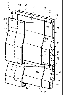
panel removed to
demonstrate how the projecting edge of the abutting insulated siding member is
received in the
mating detent. As depicted in Fig. 20, the projecting siding edge 126 is
received and positioned
neatly relative to the associated detent 128. The upper edge configuration 129
is depicted in
Fig. 21.
[00101] Rear panel configurations of abutting insulated siding panel members
are depicted in
Figs. 22 and 23. Where desired or required, the rear panel configurations and
be positioned such
that the rear configurations correspond or cooperate as desired or required.
It is contemplated that
the lower edge of the respective siding layers can be configured to receive
one another in
overlapping relationship as depicted in Fig. 23.
[00102] Insulated siding panels can be installed in abutting top-to bottom
relationship as
depicted in Figs. 24 and 25A, B where the lip formed proximate to the top of
one siding layer
engages the lip configured in the lower edge of an associated siding panel.
The upper most edge of
one insulated siding panel projects upward into the detent 150 formed in the
abutting insulated
siding panel member.
[00103] In various alternate embodiments it is contemplated that the shape
molded backing
member may be prepared in lengths greater than four feet, with lengths as
great as 20 feet being
18
CA 02572711 2007-01-02
contemplated. The shape molded backing member 112 can be attached to the
siding layer 114 at
any time prior to installation on the wall. It is contemplated that, where
desired or required, the
siding layer can be attached to the backing member at the factory or in the
field.
(00104] While the invention has been described in connection with what is
presently
considered to be the most practical and preferred embodiments, it is
understood that the invention is
not limited to the disclosed embodiments, but is intended to cover various
modifications and
equivalent arrangements included within the spirit and scope of the claims.
The claims are to be
accorded the broadest possible interpretation so as to encompass all such
modifications and
equivalent structures and instructions as permitted under the law.
19