Note: Descriptions are shown in the official language in which they were submitted.
CA 02573414 2007-01-10
Data Carrier Having a Security Element and Method for Manufacturing the
Same
The present invention relates to a data carrier, especially a value document,
such as a banknote, an identification card or the like, having a security
element that exhibits a print image and a laser marking at least partially
overlapping the print image. The present invention further relates to a
method for manufacturing such a data carrier, a method for manufacturing a
data carrier having a security element having two imprinted print images,
and a method for manufacturing a plurality of individual ups of data carriers
on a sheet or a roll.
Data carriers within the meaning of the present invention especially include
security or value documents, such as banknotes, passports, identification
documents, check forms, stocks, certificates, stamps, vouchers, plane tickets
and the like, as well as labels, seals, packaging and other elements for
product protection. In the following, the term "data carrier" encompasses all
such documents and product protection means.
Identification cards, such as credit cards or personal identity cards, have
long
been personalized by means of laser engraving. In personalization by laser
engraving, the optical properties of the substrate material are irreversibly
changed through suitable guidance of a laser beam in the form of a desired
marking. Such a laser marking makes it possible to combine the
individualization of the data carriers with security elements and to integrate
them into the print image more freely than with conventional
individualizations, for example with known numbering methods.
CA 02573414 2007-01-10
-2-
From publication US-A-4 234 214 is known a banknote having a readable
code composed of letters and numbers that comprises a sequential serial
number for uniquely marking the banknote. The readable code is applied
with a polychromatic background at a first position on the banknote in
positive form and at a second position in negative form. Here, the negative
form of the code can be produced by ablating a previously applied ink layer
with a suitably controlled laser beam.
Since, when laser marking previously applied printing layers, the same
paper path is used as with a printing machine, register variations of the same
magnitude occur here as between standard printing methods. The register
variations occur, for example, due to production tolerances in manufacturing
printing materials, printing plates and printing screens, due to spacing
variations of the printing area from the edges of the preprinted substrate
when machines are changed between different printing methods, such as
screen printing, simultaneous printing, intaglio printing and numbering, or
because the dimensions of the substrate and the plates change in the printing
process, for example in a rolling step, or the associated job steps, such as a
drying step. In unfavorable cases, the register variations can be up to +/-
3.5
mm. In general, in security printing, variations of +/-1.5 mm between
background and intaglio printing can be expected, and of + / - 2 mm between
background and screen printing. Foil elements can be applied with variations
of +/-1.5 mm with respect to a background printing.
Such register variations stand out clearly primarily in round or curved
printing elements that are marked along a concentric path or a path running
along the curve.
CA 02573414 2007-01-10
-3-
Based on that, the object of the present invention is to specify a data
carrier of
the kind cited above, and a manufacturing method, with which the
disadvantages of the background art are overcome. In particular, it is
intended to avoid register variations between two print images or between a
print image and a laser marking, or to make them largely invisible when
viewed visually.
This object is solved by the data carrier having the features of the main
claim.
A method for its manufacture, a method for manufacturing a data carrier
having a security element having two imprinted print images, and a method
for manufacturing a plurality of individual ups of data carriers on a sheet or
a roll are specified in the coordinated claims. Developments of the present
invention are the subject of the dependent claims.
According to a first aspect of the present invention, the security element of
a
generic data carrier exhibits, at least partially overlapping the print image,
a
laser modification area that is in register with the laser marking and in
whose
overlap area with the print image the visual appearance of the print image is
modified by the action of a laser beam.
In this aspect, the present invention is based on the idea of permitting
register variations between the print image and the laser marking and, in a
sub-area that is in register with the laser marking, modifying the visual
appearance of the print image such that register variations between the print
image and the laser marking recede into the background for the viewer and
instead, the (perfect) register between the laser marking and the modification
area dominate the optical appearance of the security element.
CA 02573414 2007-01-10
-4-
Here, in a preferred embodiment, it is provided that the laser modification
area forms a contour of predefined width surrounding the edge of the print
image. The characteristic dimension of the laser modification area, especially
the predefined width of the surrounding contour, is expediently matched to
the size of the register variations between the print image and the laser
marking such that all typically occurring register variations can be
compensated for.
The print image of the security element can be executed, for example, in
screen printing, offset printing, indirect relief printing, relief printing,
digital
printing, or ink-receptive or relief-embossing intaglio printing. Combinations
of printing methods can, of course, also be used.
Any printing inks can be used as printing inks, but preferably effect inks are
used, which, due to their physical properties, lend the print image additional
counterfeit protection and are difficult to imitate. The imprinted effect
layer
can especially consist of metal, a metallic ink or an ink containing
interference layer pigments and be bronze, copper, silver or gold colored.
An ink mixture that exhibits a laser-radiation-absorbing mixture component
and a laser-radiation-transparent mixture component can also be used as the
printing ink. The laser marking of the print image then becomes visually
perceptible due to a laser-induced irreversible change in the optical
properties of the ink mixture. In particular, under the action of the laser
radiation, the absorbing mixture component can be bleached, vaporized,
changed in its reflection properties or transformed by a chemical reaction
into a material having other optical properties.
CA 02573414 2007-01-10
-5-
Especially optically variable liquid crystal pigments are appropriate as the
laser-radiation-transparent mixture component, and for the absorbing
mixture component, optically variable interference layer pigments, for
example. Other ink components that are irreversibly changeable in their
optical properties, such as an intaglio ink, a metallic effect ink or metallic
pigments, a luminescent ink or luminescent pigments, glossy pigments or a
thermochromic ink, may also be used as the absorbing mixture component.
The print image can also consist of multiple stacked ink layers, at least one
of
the ink layers being laser-radiation-absorbing or including absorbing
components. In this way, the visual design of the print image can be
separated from the requirements for laser beam absorption.
Upon laser inscription, the layers disposed above an absorbing ink layer can
be ablated together with said layer. In the print image, a liquid crystal
layer
can be provided above an infrared-absorbing printing layer, for example. The
IR-transparent liquid crystal layer is then ablated together with the IR-
absorbing background layer at the laser-exposed locations.
The print image can also include a liquid crystal layer above a
thermochromic ink layer, the thermochromic ink layer being irreversibly
blackened at the laser-exposed locations such that a clearly visible dark
marking is created within the optically variable print image.
In a particular embodiment, the print image is designed as an oval or circle,
and especially in the form of a coin likeness. This print image design is
preferably combined with metallic-appearing printing inks, a foil patch
element or a relief embossing. It is appropriate for the laser marking,
through
typical elements such as a centered portrait likeness or patterns or writing
or
CA 02573414 2007-01-10
-6-
number depictions around the edge, to take on and amplify the coin
character.
In other, likewise advantageous embodiments, the print image forms a
pattern, especially a line pattern, such as a Guilloche pattern composed of
regularly interlaced lines. Other finely structured patterns such as are often
used especially in security printing may also be used.
The laser marking of the security element can be designed in the form of
patterns, characters or codes. In particular, the marking can consist of
alphanumeric characters, such as are commonly used for serial numbers of
value documents, or form a bar code, that is, a pattern sequence composed of
bars and spaces that normally represent a binary numeric string. Two-
dimensional codes, which offer particularly highly condensed recording, can
also be used. Furthermore, the laser marking can include any symbols or
graphic depictions that can be distributed practically without limits on the
surface of the data carrier.
Within the laser marking or the laser modification area, different laser
parameters can be used to achieve different effects or different effect
intensities. For example, the line width of a line marking or the point size
of a
grid marking can be changed by focusing the laser beam. The focus can be
changed with the requisite high speed via a motorized beam expansion in
front of the scan head, or through so-called liquid lenses. Through different
laser output, semitransparent areas can be produced next to areas having
completely ablated printing ink. With the appropriate laser output, it is also
possible to foam the substrate, which can lead to an easily perceptible
tactility. The modulation frequency of the laser or the pulse sequence in
pulse mode can be varied.
CA 02573414 2007-01-10
-7-
As already explained, the visual appearance of the print image is
advantageously modified by the action of the laser beam also in the overlap
area between it and the laser marking. In at least one of the overlap areas of
the laser marking and the laser modification area with the print image, the
printing ink of the print image can be partially or completely ablated by the
action of the laser beam. A partial ablation can lead, for example, to
lightened, bleached or semitransparent areas within the print image, with
reduced thickness of the ink layer. The partial ablation can also consist in
the
introduction of a finely engraved pattern that forms, for example, a
decorative edge around the print image. Likewise, the optical properties of
the print image can be irreversibly changed in at least one of the overlap
areas.
In an advantageous embodiment of the security element, the data carrier is
not visually changed outside of the overlap area of the laser modification
area and the print image. The effect of the laser modification is then limited
to the area of the print image. Alternatively, the laser parameters for
modification can be set such that, outside the overlap area of the laser
modification area and the print image, a tangible marking having a relief
structure is produced in the data carrier.
In a development of the present invention, below the print image is provided
an ink layer, especially a security ink layer, that is exposed, activated or
deactivated in at least one of the overlap areas by the action of the laser
beam. For the security ink layer, for example, up-conversion materials,
phosphorescent, fluorescent or other luminescent substances, magnetic inks,
thermoluminescent or electroluminescent inks, as well as inks that absorb
outside the visible spectral range may be used. In this way, machine-readable
CA 02573414 2007-01-10
-8-
features can be introduced individually together with the laser marking or
the laser modification. Further, with the aid of the security inks, it can be
checked whether the security element is laser-marked.
The invention further includes a method for manufacturing a data carrier
having a security element, in which
a) a print image is imprinted on a data carrier substrate,
b) a laser marking at least partially overlapping the print image is
produced by the action of a laser beam, and
c) by the action of a laser beam is produced, in register with the laser
marking, a laser modification area at least partially overlapping the
print image and in whose overlap area with the print image the visual
appearance of the print image is modified.
The laser modification area is preferably produced in the form of a
surrounding contour of predefined width around the edge of the print
image. According to an advantageous embodiment of the method, the laser
marking is produced in step b) having certain register variations between the
print image and the laser marking, and the laser modification area is
produced in step c) having a characteristic dimension that is matched to the
size of the register variations, especially a predefined width of the
surrounding contour that is matched to the size of the register variations.
The laser marking and the laser modification area are advantageously
produced in the same operation with the same laser marker such that they
are in perfect register with one another.
CA 02573414 2007-01-10
-9-
The laser marking and the laser modification area can be produced in any
sequence. In some embodiments, however, it is advantageous for the laser
modification area to be produced first, and the laser marking then formed at
least partially within the laser modification area.
The laser marking and the laser modification area are preferably produced
for a plurality of individual ups of data carriers on a sheet or a roll.
The invention further includes a method for manufacturing a data carrier
having a security element, in which
a) a first print image is imprinted on a data carrier substrate,
b) a second print image is imprinted on the data carrier substrate, the
two print images exhibiting certain register variations, and
c) by the action of a laser beam, a laser modification area at least partially
overlapping the two print images is produced in whose overlap area
with the print images the visual appearance of each print image is
modified.
Here, the laser modification area in step c) is advantageously produced
having a shape and size that is matched to the size of the register
variations.
Within the meaning of the present invention, the first or the second print
image can be produced with any suitable printing methods, especially with
those mentioned above, "print image" being intended to also mean a relief
embossing, preferably produced in non-ink-receptive intaglio printing.
CA 02573414 2007-01-10
-10-
In a further aspect, the present invention includes a method for
manufacturing a plurality of individual ups of data carriers on a sheet or a
roll, in which
a) on the sheet or the roll is imprinted an overall print image that
comprises the print images of multiple individual ups,
b) the position of the print images on the sheet or the roll is detected, and
c) based on the detected position of the print images, laser markings are
produced in the individual ups by the action of a laser beam.
In a preferred embodiment of the method, in step a), on the sheet or the roll
are printed, together with the print images, register marks, especially
register
lines or register crosses, whose positions are detected in step b) as a gauge
for
the position of the print images.
Here, in a variation of the present invention, with every print image is
printed an associated register mark whose position is detected in step b) as a
gauge for the position of the associated print image. Here, the detection can
occur in only one direction in space, such as the direction of movement of the
sheet or the roll, or in two directions in space. In the last case,
advantageously, register crosses are used as register marks, and in the first
case, register lines suffice.
According to another variation, for each of a group of print images, for
example for a row of ups, an associated register mark is printed whose
position is detected in step b) as a gauge for the position of the print
images
CA 02573414 2007-01-10
-11-
of the associated group. Here, however, the lower outlay is met with lower
detection precision.
The position of the register marks in step b) can advantageously also be
detected by imaging sensors, especially by line scan cameras or area scan
cameras.
Alternatively, in step b), the imaging sensors can also detect the positions
of
the print images from characteristic features of the print images, so without
using register marks. In this case, additionally, data in the print images can
be read by the imaging sensors in step b) and, based on this data, the
information content of the laser marking defined. In step c), laser markings
having information content defined in this way are then produced in the
individual ups.
As the laser source for the marking or modification of the print image,
advantageously, an infrared laser in the wavelength range from 0.8 m to
3 m, especially a Nd:YAG laser is used. To accommodate the high
processing speeds in security printing, when marking, the laser beam is
expediently guided across the security substrate at a speed of more than 1000
mm/ s, preferably of more than 2000 mm/ s, particularly preferably of about
4000 mm/s or more.
Further exemplary embodiments and advantages of the present invention are
explained below by reference to the drawings, in which a depiction to scale
and proportion was omitted in order to improve their clarity.
Shown are:
CA 02573414 2007-01-10
-12-
Fig. 1 a schematic diagram of a banknote, according to an exemplary
embodiment of the present invention, that is provided with a
security element in the shape of a coin
Fig. 2 in (b), a schematic diagram of a security element according to
the present invention, and in (a), an intermediate step in its
manufacture,
Fig. 3 to 5 further exemplary embodiments of security elements
according to the present invention having perfect register
between the print image and the laser marking,
Fig. 6 a sheet having a plurality of individual ups and plotted
spacings of the planned laser markings, to explain a method
according to the present invention,
Fig. 7 in (a) to (c), three steps in compensating the register variations
of two print images of a security element with the aid of a
laser modification area,
Fig. 8 a block diagram to explain a method according to the present
invention in which the positions of the print images are
detected by sensors,
Fig. 9 a schematic diagram of a vector laser coder to explain its
operating principle
Fig. 10 a schematic diagram of a vector laser coder for inscribing a
security sheet,
CA 02573414 2007-01-10
-13-
Fig.11 a section of a security sheet having a plurality of individual
ups and having register lines at each row of ups, and
Fig. 12 a section of a security sheet as in fig. 11, having register
crosses at each individual up.
The invention will now be explained using a banknote as an example. Fig. 1
shows a schematic diagram of a banknote 10 that is provided with a security
element 12 in the form of a coin. The security element 12 exhibits a circular
print image 14 that is imprinted by means of screen printing technology with
a metallic ink, for example a silver ink, on the banknote substrate.
Further, the security element 12 is provided with a laser marking 16, for
example a serial number, that runs along the curve of the print image 14. To
increase the coin character of the security element 12, it is typically
provided
with further graphic motifs or alphanumeric elements, which are not
depicted in fig. 1. To increase counterfeit security, the laser-produced
motifs
of the coin 12 can be applied repeatedly to the banknote with other
techniques, for example as a die-stamped motif or as a watermark.
In their visual appearance, the print image 14 and the laser marking 16 are in
perfect register with one another. The present invention provides two ways
to achieve this registration.
First, the procedure according to the first aspect of the present invention is
explained with reference to figures 2 to 6. For this, fig. 2 shows, in (a), a
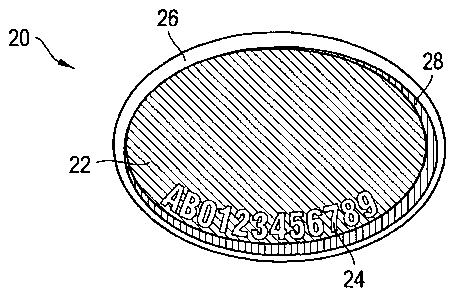
security element 20 having an oval print image 22 that is provided with a
laser marking 24. Due to the above-described register variations between the
CA 02573414 2007-01-10
-14-
print image and the laser marking, the alphanumeric marking 24 does not
precisely follow the curve of the print image 22. Although the size of the
deviation is depicted exaggeratedly in fig. 2(a) for illustration, the human
eye
is very sensitive to such deviations, particularly in round or curved
elements,
such that even relatively small deviations can stand out intrusively.
According to the present invention, the security element is thus, as shown in
fig. 2(b), additionally provided with, partially overlapping the print image,
a
laser modification area 26 that forms a contour surrounding the edge of the
print image 22. In the overlap area 28 of the laser modification area 26 with
the print image 22, the printing ink of the print image is ablated or
transformed into a transparent modification. Here, the laser modification
area 26 is in perfect register with the laser marking 24, since it is produced
together with same in the same operation by the same laser marker and
controlled by the same computer. Here, the ablation of the printing ink can
occur in that the laser beam is directed directly at the printing ink and acts
from the side on which the printing ink is located. Alternatively, the laser
beam can also act on the reverse, i.e. on the surface of the substrate facing
away from the printing ink, and achieve the desired effects on the side of the
substrate on which the printing ink is located.
When the finished security element 20 in fig. 2(b) is viewed, the visual
impression of perfect register of the laser marking 24 and the still visible
portion of the print image 22 results. Such perfect register in curved
elements
constitutes an obstacle that is very difficult for counterfeiters to overcome
and, particularly due to the aforementioned sensitivity of the human eye to
small register variations, forms a security element with high counterfeit
security.
CA 02573414 2007-01-10
-15-
The sequence in which the laser marking 24 and the laser modification area
26 are produced is, in principle, arbitrary. As explained below, depending on
the desired effect, it can be advantageous to produce first the laser marking
24 or first the laser modification area 26.
The print image 22 to be provided with the laser marking can be exposed or
surrounded by adjacent print images. In the latter case, it is advantageous
for
the printing inks of the adjacent print images to be laser-radiation
transparent such that, depending on the laser parameters used in producing
the laser modification area 26, no marking or a tangible marking is created
there.
Figures 3 to 5 show further exemplary embodiments of security elements
according to the present invention having perfect register between the print
image and the laser marking. As the exemplary embodiment in fig. 3 shows,
in which the same reference numbers as in fig. 2 indicate identical elements,
the principle described can also be applied to security elements 20 having
complex shapes. Instead of ablating the printing ink contiguously in the
overlap area 28, a decorative edge 28 can also be produced around the print
image 22 through suitable control of the laser writer. Optically, the
contiguous inside of the print image dominates such that here, too, the
impression 22 of perfect register between the print image and the laser
marking is created.
As shown in the exemplary embodiment in fig. 4, the laser marking 24 can
also be guided beyond the edge of the print image 22, where it effects a
marking effect in the data carrier substrate, for example a blackening 30. In
this way, special contrast effects can be produced. For example, the marking
portion 32 that overlaps with the print image 22 and in which only the
CA 02573414 2007-01-10
-16-
printing ink is removed and the remaining laser energy is not sufficient to
blacken the substrate appears white against the silver- or gold-colored
background of the print image 22, while the laser effect outside the print
image 22 causes a blackening 30 of the otherwise light substrate material.
In designs having laser markings protruding beyond the edge of the print
image, the laser modification area is advantageously produced first to ensure
that the location of the shift in contrast or color coincides with the edge of
the
remaining print image.
In the further variation of the present invention depicted in fig. 5, the
impression of registration of print image and laser marking is created in
that,
in the print image or in the substrate of the data carrier, an areal change is
created with a first set of laser writer parameters and then, in the laser
modification area produced in this way, with a second set of parameters, a
laser marking having an effect that differs from the areal change is produced
in register. The areal change can consist, for example, in a removal of ink or
ink components, or a lightening or bleaching.
In the exemplary embodiment shown in fig. 5(a), the line print pattern 40 is
lightened in the laser modification area 42 and a tangible marking 44 is
produced in register therewith at significantly higher laser intensity. As the
exemplary embodiment in fig. 5(b) shows, the areal change 42 can also leave
in the print pattern 40 a print image area 46 in which the laser marking 44 is
then produced.
As already explained under fig. 2, the laser beam can be guided on the front
or on the reverse of the substrate.
CA 02573414 2007-01-10
-17-
With reference to fig. 6, when manufacturing a plurality of individual ups of
banknotes 10 on a sheet 50 or a roll, the laser process is initiated once per
sheet or roll. If the start signal is given at the upper left corner of the
sheet,
the spacings 52 (in the x-direction) and 56 (in the y-direction) lead to the
security element to be marked in the first banknote.
In a dummy sheet, the spacings 54-i, i=1 ... 3 (in the x-direction) and 58-j,
j=1
... 6 (in the y-direction) between the security elements to be marked are
constant, and the production of the laser markings and the laser modification
areas then occurs with predefined fixed spacings 54 and 58. Here, the
precision of the lasering in relation to the print image is on the same order
as
for a conventional numbering. However, since, for the viewer, the laser
marking is put into visual relationship with the laser modification area
produced in the same job step, practically no register variations are
perceptible for the viewer.
However, for the trained eye or with the aid of optical devices, it can be
proven beyond doubt, for example on the basis of adhesive residues, that the
security element was provided with a laser-produced register. Also,
substances that are invisible to the human eye can be systematically
introduced into the printing layer or a layer lying thereunder. In this way,
the presence or absence of a laser modification can serve as an additional
security feature.
If necessary, the coordinates of the elements to be marked can also be
detected more precisely. For example, the spacings 54-1, 54-2, 54-3 ... (in
the
x-direction) and 58-1, 58-2, 58-3 ... (in the y-direction) between the sheet
elements to be marked can be determined individually on the resting sheet
and entered into the control unit of the laser marker to compensate for
changes in the length and/or width of the sheet 50. Here, the position
CA 02573414 2007-01-10
-18-
measurement can be done individually for columns and rows or even
individually for each up, resulting in spacings 52-i, 54-il, 54-i2, 54-i3,
..., for
the i-th up row being obtained in the x-direction, and spacings 56-j, 58 j1,
58-
j2, 58-j3, ..., for the j-th up column in the y-direction.
The above-described approach can also be used to manufacture a data carrier
having a security element having two print images, in which the two print
images initially exhibit certain register variations.
For this, fig. 7 shows, in (a), two print images 60 and 62 having register
variations 64 and imprinted in succession on a data carrier substrate. By the
action of a laser beam, a laser modification area 66 overlapping the two print
images 60, 62 is produced in whose overlap area 68 with the print images the
printing ink of the appropriate print image 60 or 62 is ablated, as shown in
fig. 7(b). The laser parameters are selected such that the data carrier
substrate
is not changed outside of the overlap area 68. Thus, the registered transition
70 depicted in fig. 7(c) remains. It is understood that this method can also
be
applied to more than two print images. Here, the print images can be applied
on the front and/or reverse.
According to the further aspect of the present invention, register variations
between the print images of a sheet or a roll and the appropriate laser
markings are avoided in that the positions of the print images or certain
elements of the print images are detected by sensors, and the laser markings
are produced based on the detected positions.
The basic procedure is illustrated in the block diagram in fig. 8. The method
begins at reference number 80, where the sheet feed into the machine takes
place. The sheets 82, each of which includes a plurality of individual ups of
CA 02573414 2007-01-10
-19-
data carriers, are processed with a certain web or sheet speed 84. The speed
is, for example, about 10,000 sheets/hour, which, depending on the design,
corresponds to web speeds of 2 m/ s to about 3.5 rn/s. Such web speeds are
also achieved when processing web-shaped materials. The coordinates of
pre-printed register marks or certain points in the print image of the
individual ups are detected (reference number 86) and transmitted to a
computing unit 88 to determine the marking positions. The computing unit
88 controls a laser marker 90, described in greater detail below, to apply the
laser markings in the correct positions within the print image of each
individual up. Lastly, the marked sheets are output at reference number 92.
Fig. 9 shows schematically the scan head 100 of a vector laser coder with
which the security element 102 of an individual up is provided with a laser
marking 104. An infrared laser beam 106 is deflected via two movable
mirrors 108, one of the mirrors producing the deflection in the x-direction
and the other mirror the deflection in the y-direction. A plane-field lens 110
focuses the laser beam 106 on the security element 102, where it produces, in
the manner described above, the laser marking 104 and possibly also a laser
modification area.
The security element 102 and the data carrier substrate move during the
marking operation at a certain speed v. This speed is detected by sensors
(reference number 84 in fig. 8) and transmitted to the computer 88 (fig. 8) to
control the movement of the mirrors 108 such that the substrate speed v is
compensated for when inscribing. The marking method can thus be
employed particularly advantageously for the non-contact marking of value
documents that are processed at high speeds, as is common in printing
shops.
CA 02573414 2007-01-10
-20-
The security elements 102 of a sheet can also be marked, for example, by
means of a matrix of punctiformly emerging laser beams or by means of
large-cross-section beams that are partially covered by a stencil. Such
stencils
can be implemented to be automatically variable. If it is not possible or not
desired to guide the radiation in line with the substrate speed, it is also
possible to mark moving substrates by choosing a short exposure time. Beam
control through polygon mirrors is also possible.
Depending on the substrate used, CO2 lasers, Nd:YAG lasers or other laser
types in the wavelength range from UV to far infrared may be used as the
radiation sources, the lasers also often working advantageously with
frequency doubling or tripling. Preferably, however, laser sources in the near
infrared are employed, since this wavelength range is well suited to the
absorption properties of the data carrier substrates and printing inks used.
Depending on the application, the spot size of the laser radiation can be
varied from a few micrometers to a few millimeters, for example by changing
the distance between the plane-field lens 110 and the security element 102.
Preferably, spot sizes of around 100 m are used.
The continuous output of the laser marker used typically lies between a few
watts and a few hundred watts. Nd:YAG lasers can be operated with laser
diodes for lower total output with smaller construction dimensions and high
beam quality, or with pump lamps for high outputs. In order to not reduce
the speeds of an industrial value document production line, the laser
markings or laser modifications are advantageously executed with very fast-
moving galvanometers that can guide the beam across the substrate at more
than 1000 mm/ s, preferably at up to 4000 mm/ s or more. At these marking
speeds, only a small proportion of energy is deposited in the substrate or the
CA 02573414 2007-01-10
-21-
security element 102 for each section, so that, advantageously, lamp-pumped
Nd:YAG lasers with an output of about 100 watts are used.
By varying the inscription parameters, such as the laser output, exposure
time, spot size, inscription speed, operating mode of the laser, etc., the
marking results can be varied within a broad scope. In this way, in addition
to the partial or complete ablation or the partial or complete modification of
ink or effect layers, other markings, such as blackenings in the data carrier
substrate or tangible markings having a relief structure, can also be produced
by the laser. Such tangible markings preferably have a height of 30 to 100 m.
The markings are undertaken for example with a Nd:YAG laser having a
fundamental wavelength of 1064 nm and exhibiting an average output of
26 W and a modulation frequency of 8 kHz. The diameter of the laser beam
on the substrate (spot size) is about 100 m and the traverse speeds of the
laser beam across the substrate 250 to 4000 mm/s.
Fig. 10 shows a laser marker 120 in which, with a plurality of lasers, a sheet
122 is simultaneously provided with a laser marking and a laser modification
area. In the example shown, the sheet 122 exhibits six columns and six rows
such that 36 individual ups 124 of bank notes or other data carriers are
disposed on this sheet. For each column, disposed above the printing sheet
122 is a laser tube 126 that, together with the associated scan head 128,
produces the laser markings or modifications in each of the individual ups
124 disposed in that column. The throughput can be greatly increased
through this configuration since a single laser beam does not have to be
moved across the entire printing sheet, but rather merely one scanning field
is impinged on between the columns of the printing sheet. The impingement
CA 02573414 2007-01-10
-22-
on the individual ups occurs, as described for fig. 9, through the deflection
of
the laser radiation by means of the mirrors contained in the scan heads 128.
An exemplary embodiment for the detection of the position of the print
images of the individual ups will now be explained with reference to fig. 11.
For the following description, the y-coordinate is selected to be along the
column direction of the individual ups, and the x-coordinate along the row
direction.
As shown in fig. 11, for each column of individual ups 132 having print
images 134 to be marked, an associated register line 136 is printed on the
sheet 130. A printing mark or contrast mark sensor detects the register line
136 prior to the laser inscription and controls the y-coordinate of the
marking
accordingly. The register line 136 is printed in the printing process to which
the laser is to be matched, so that it is subject to the same register
variations
as the print images 134 of the row of ups. If the length of the printing sheet
is
changed in the colunm direction, for example by drying or rolling out, this
can be accounted and compensated for by detecting the position of the
register lines 136 for the associated print images 134.
Here, an associated register line can also be printed for each individual up.
The register lines can then be detected and analyzed individually for each
column of ups, thus achieving greater precision for a non-uniform change in
the y-coordinate across the row direction x, for example due to non-uniform
drying or trapezoidal rolling.
Instead of the register lines, distinctive points in the print image of the
data
carrier can often also be used for detection. The individual ups can then be
arranged to save space on the sheet.
CA 02573414 2007-01-10
-23-
Fig.12 shows a sheet 140 in which, for each individual up 142, an associated
register cross 146 is printed. This permits, in addition to the y-coordinate,
the
position of the print images 144 to be determined in the row direction x. To
be able to use a contrast mark sensor here, too, the scanning light beam can
be guided, for example with the aid of a polygon wheel, perpendicular to the
direction of movement of the sheet, the shortest traverse paths possible being
selected to avoid imprecisions.
The scanning in the x-direction, as well as in the y-direction, can also occur
with the aid of imaging sensors, for example with a CCD or CMOS line scan
camera. The scanning frequency of such sensors is high enough to be able to
detect each individual up despite the high web speeds. To detect register
marks 146 or distinctive points in the print image 144, advantageously, one
row is used per column of ups, as denoted by the line scan cameras 150
plotted in dotted lines in fig. 12.
The individual rows read out can either be processed directly or, with the aid
of a meter defined by the speed measurement of the sheets, assembled into
images and then analyzed. The analysis is done with special hardware
and/ or software, particularly digital signal processors and PGA
(programmable gate array) components being suitable. Due to the requisite
short exposure times, very bright and well-adjusted lighting is
recommended, such as flash bulbs that are switched synchronously with the
image feed.
Instead of line scan cameras 150, area scan cameras that record two-
dimensional information can also be used. In this way, the print image of the
overall appearance can be detected. To achieve high resolution and thus
CA 02573414 2007-01-10
-24-
good register precision, here, too, it is appropriate to use one area scan
camera per column of ups. In particular, CMOS cameras are appropriate
here, as these achieve high scanning frequencies with high resolution, and
support fast signal processing well. Otherwise, the above details apply with
regard to signal processing and lighting.
Since area scan cameras detect the entire print image, also less distinctive
points in the print image can be detected and used as the basis for position
determination. The subsequent data processing is then easier to realize.
Furthermore, the detected images can serve as a quality control for preceding
printing operations.
In the variations in which imaging sensors are used to determine position,
they can additionally read print image data that determine or co-determine
the information content of the laser marking.
For example, a camera can read in the print image a numeric string applied
in letterpress printing, and the read data can be used to produce an
appropriate matrix code having the same information content and introduce
it as a laser marking into the print image of this individual up. The
information content of the laser marking can also be merely derived from the
read information content and, for example, constitute a check digit for the
read numbering, or repeat a portion of the read numbering.