Language selection

Search

Patent 2574647 Summary

Third-party information liability

Some of the information on this Web page has been provided by external sources. The Government of Canada is not responsible for the accuracy, reliability or currency of the information supplied by external sources. Users wishing to rely upon this information should consult directly with the source of the information. Content provided by external sources is not subject to official languages, privacy and accessibility requirements.

Claims and Abstract availability

Any discrepancies in the text and image of the Claims and Abstract are due to differing posting times. Text of the Claims and Abstract are posted:

  • At the time the application is open to public inspection;
  • At the time of issue of the patent (grant).
(12) Patent: (11) CA 2574647
(54) English Title: CONCRETE BLOCK
(54) French Title: BLOC EN BETON
Status: Expired and beyond the Period of Reversal
Bibliographic Data
(51) International Patent Classification (IPC):
  • E04C 01/00 (2006.01)
(72) Inventors :
  • AZAR, TONY J. (Canada)
(73) Owners :
  • TONY J. AZAR
(71) Applicants :
  • TONY J. AZAR (Canada)
(74) Agent: MOFFAT & CO.
(74) Associate agent:
(45) Issued: 2010-03-30
(22) Filed Date: 2007-01-19
(41) Open to Public Inspection: 2008-03-29
Examination requested: 2007-01-19
Availability of licence: N/A
Dedicated to the Public: N/A
(25) Language of filing: English

Patent Cooperation Treaty (PCT): No

(30) Application Priority Data:
Application No. Country/Territory Date
2,560,676 (Canada) 2006-09-29

Abstracts

English Abstract

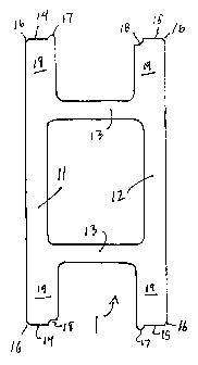
A concrete block for construction, the block having a front wall and a rear wall. The front and rear walls are spaced apart by a pair of transverse webs. Each of the front and rear walls comprises a middle portion and a pair of end portions, wherein the end portions have a uniform thickness that is greater than the thickness of the middle portion.


French Abstract

L'invention concerne un bloc en béton pour la construction, le bloc ayant un mur avant et un mur arrière. Les murs avant et arrière sont espacés entre eux par une paire de toiles transversales. Chacun des murs avant et arrière comprend une partie intermédiaire et une paire d'extrémités, lesquelles ont une épaisseur uniforme supérieure à celle de la partie intermédiaire.

Claims

Note: Claims are shown in the official language in which they were submitted.


WE CLAIM:
1. A concrete block for construction, said block having a front wall and a
rear wall, said
front and rear walls being spaced apart by a pair of transverse webs, each of
said front
and rear walls comprising a middle portion and a pair of end portions, each
said end
portions having a uniform thickness that is greater than the thickness of said
middle
portion, wherein each said end terminates in a flat surface perpendicular to
said front and
rear walls said flat surfaces on each respective end of said front and rear
walls being
coplanar and wherein each said flat surface on each end of a said front and
rear wall is
provided with a vertically extending, integrally formed bead or groove, each
said groove
being dimensioned to fit with a said bead.
2. The concrete block as claimed in claim 1, wherein said middle portions have
a thickness
about the same as said webs, thereby defining, with said webs, a vertically
extending box
channel.
3. The concrete block as claimed in claim 1 or claim 2, wherein there is a
bead and a groove
at each end of a said block, and a bead and a groove at each end of a said
wall.
4. The concrete block as claimed in claim 1 or claim 2, wherein said block is
provided with
an end wall at one end thereof.
5. The concrete block as claimed in claim 4, wherein said front and rear walls
are provided
on their outer facing surfaces, with grooves alignable with said beads.
6. The concrete block as claimed in claim 5, wherein said end wall is provided
on its outer
surface with grooves alignable with said beads.
6

Description

Note: Descriptions are shown in the official language in which they were submitted.


CA 02574647 2009-03-02
CONCRETE BLOCK
FIELD OF THE INVENTION
The present invention relates to the field of concrete building products, and
in particular,
provides an improved concrete building block that can be used in dry stack,
i.e., mortarless
building environments.
DISCLOSURE OF PRIOR ART
There are numerous building blocks available on the market, and one of
particular relevance to
the present invention is known to be of a rectangular design, with
substantially parallel front and
rear walls that are provided with deep grooves or projecting tongues at their
ends, so as to permit
consecutive blocks in a course of blocks be interlocked, to form a straight
and level course of
blocks. The front and rear walls are spaced apart by transversely extending
webs. The walls
increase gradually in thickness from the web to the ends thereof.
SUMMARY OF THE INVENTION
The block of the present invention is, essentially, a modified and improved
version of the
aforesaid block. The specific improvements made in the design of the block of
the present
invention include thickening the front and rear walls of the block, from the
transverse web, and
utilizing vertical beads that project outwardly from the ends of the wall
panels for block to block
alignment, instead of tongue and groove, or overlapping joints for end to end
connection. A
further significant improvement of the present invention is that the corner
block may, if desired,
be used as a stretcher, or can be used to create T-walls or four-way corners.
The upper and lower surfaces of the block of the present invention may be
substantially flat or
may be profiled.
In a broad aspect, then, the present invention relates to A concrete block for
construction, said
block having a front wall and a rear wall, said front and rear walls being
spaced apart by a pair
of transverse webs, each of said front and rear walls comprising a middle
portion and a pair of
1

CA 02574647 2009-03-02
end portions, each said end portions having a uniform thickness that is
greater than the thickness
of said middle portion, wherein each said end terminates in a flat surface
perpendicular to said
front and rear walls said flat surfaces on each respective end of said front
and rear walls being
coplanar and wherein each said flat surface on each end of a said front and
rear wall is provided
with a vertically extending, integrally formed bead or groove, each said
groove being
dimensioned to fit with a said bead.
BRIEF DESCRIPTION OF THE DRAWINGS
In drawings that illustrate the present invention by way of example:
Figure 1 is a top view of a stretcher block embodying the present invention;
Figure 2 is a top view of a corner block embodying the present invention;
Figure 3 is a top view of a corner connection using a stretcher and a corner
block
according to the present invention;
Figure 4 is a top view of a half length block, according to the present
invention;
Figure 5 is a top view of a preferred embodiment of a stretcher block
according to the
present invention;
Figure 6 is a cross section through line A-A in Figure 5;
Figure 7 is a cross section through line B-B in Figure 5;
Figure 8 is a cross section through line C-C in Figure 5;
Figure 9 is a perspective view of the block of Figure 5;
Figure 10 is an end view of detail D from Figure 8;
Figure 11 is a top view of a preferred embodiment of a corner block according
to the
present invention;
Figure 12 is a side view of the block of Figure 11;
Figure 13 is a cross section through line A-A in Figure 11;
Figure 14 is an end view of the open end of the block of Figure 11;
Figure 15 is a cross section through line B-B in Figure 11;
Figure 16 is a perspective view of the block of Figure 11;
Figure 17 is an end view of detail C in Figure 15;
2

CA 02574647 2009-03-02
Figure 18 is a top view of a half size block according to the present
invention;
Figure 19 is an end view of the closed end of the block of Figure 18;
Figure 20 is a cross section through line A-A in Figure 18;
Figure 21 is a cross section through line B-B in Figure 18;
Figure 22 is an end view of the open end of the block of Figure 18;
Figure 23 is a perspective view of the b lock of Figure 18;
Figure 24 is an end view of detail C in Figure 21;
Figure 25 is a top view of a plurality of blocks of the present invention,
assembled in a
course;
Figure 26 is a perspective view of the course of blocks shown in Figure 25.
DETAILED DESCRIPTION
Referring now to the drawings, the present invention provides a building
system that uses three
specially designed blocks:
1. a stretcher block 1
2. a corner block 2
3. a half length block 3.
Each stretcher block 1 and corner block 2 is twice as long from end to end as
it is wide, from
front surface to rear surface. This permits blocks to be placed in staggered
courses and to form
corners. Detailed dimensional views of a preferred embodiment of a stretcher
block according
to the present invention are shown in Figures 5-9.
Each stretcher block 1 has a front wall 11, a rear wall 12 parallel thereto,
and webs 13
transversely extending between the front and rear walls 11, 12. The front and
rear walls 11, 12
end in vertically extending front and rear end wall surfaces 14, 15. At each
end of the block, end
wall surfaces 14, 15 are coplanar with each other.
Each corner of the block, where a front 11 or rear 12 wall ends is beveled
with a small angled
3

CA 02574647 2009-03-02
surface 16, which may be convex, concave or planar. At the inside edge of end
wall surfaces, a
vertical bead 17 or groove 18 is formed. One bead 17 and one groove 18 is
formed at each end
of the block, so that each end is provided with a groove 18 and a bead 17. The
front 11 and rear
12 walls each have one groove and one bead formed therein (at opposite ends)
whereby blocks
laid end to end in a course will have the bead of one wall fitting into the
groove of the next, with
the end walls 14, 15 on adjacent blocks firmly abutting each other.
The ends 19 of the front and rear walls are considerably thicker than the
portions of the walls
between the webs 13, which adds needed strength to the ends to protect them
against cracking
during transport. The middle portions of the walls 11, 12 are not as
susceptible to breakage, since
they form a rigid box channel with the transverse webs 13.
Referring now to Figure 2 and in detail with dimensions, to a preferred
embodiment shown in
Figures 11-17, the present invention provides a corner block 2 that is
provided with front 21, rear
22 walls connected together by first and second transverse webs 231, 232.
Inner transverse web
231 may be eliminated entirely, if desired, to improve the water resistance of
walls constructed
with the blocks of the present invention. That is, eliminating web 231 will
permit concrete or
grout poured into a wall constructed with the blocks of the present invention
more freely, so that
a continuous concrete core is formed around the corners of such a wall.
The front and rear walls 21, 22 are also connected together, at one end, by a
planar end wa1124.
The other ends 29 of the front and rear walls 21, 22 of corner block 2 are
thickened similar to
the ends of front and rear walls 11, 12 of the stretcher block, and also have
coplanar end surfaces
25, 26. The corners 16 of the corner block are beveled in a manner similar to
the stretcher block
1. Accordingly, corner 2 and stretcher 1 blocks can be aligned end to end in a
straight line.
Moreover, the end surfaces 25, 26 of walls 21, 22 of the corner blocks 2 are
provided with beads
17 and grooves 18 in a manner similar to stretcher block 1.
The front and rear walls 21, 22 are provided with grooves 28 on their surfaces
alignable with
4

CA 02574647 2009-03-02
beads 17 of a stretcher or corner block. The grooves 28 are also provided on
the outer surface
of end wall 24. Grooves 28 are positioned on the walls 21, 22 such that a
stretcher 1 can be
butted against a corner block 2 firmly and snugly, to construct a right angle
corner. Grooves 28
are provided on each wall 21, 22 to permit right or left corners being made
without special right
and left corner blocks. Grooves 28 are provided on end wall to permit
stretcher blocks to be
aligned with the closed end wall 24 of a corner block 2. This novel feature
permits the easy
construction of four way corner, or cross-shaped wall structures using the
present invention.
This feature also permits the corner block to be used, if desired, as a
stretcher block.
The present invention also provides a half-width block 3, as shown in Figure 4
and in
dimensional detail in a preferred embodiment in Figures 18-23. Use of this
block permits walls
to be constructed with vertical non-corner edges, such as in connection with
doors and windows.
Half-width blocks may also be used in the construction of four-way corners.
Half-width blocks are provided with four equal length walls 31, each of which
is provided with
vertical grooves 32 spaced from the beveled corners 33. Grooves 32 are
alignable with the beads
17 on the ends of the stretcher 1 or corner blocks.
It will be observed that because the ends 14, 15 of the front and rear walls
of the stretcher 1 are
coplanar (as are the ends 25, 26 of the front and rear panels of a corner
block 2), then aligning
a course of stretchers is simplified, as is making a corner square.
It will also be understood that after a wall or other structure is built using
the blocks of the
present invention, the wall should the be filled with concrete or grout, so as
to create a
continuous concrete wall, with no cracks or seams extending therethrough. It
if becomes
necessary to lay the blocks in such a way that a seam extending through a wall
is created, then
durable caulk, or mortar should be applied to the entire inner surface of such
a crack or seam,
to ensure the wall is water resistant to the maximum extent.
5

Representative Drawing
A single figure which represents the drawing illustrating the invention.
Administrative Status

2024-08-01:As part of the Next Generation Patents (NGP) transition, the Canadian Patents Database (CPD) now contains a more detailed Event History, which replicates the Event Log of our new back-office solution.

Please note that "Inactive:" events refers to events no longer in use in our new back-office solution.

For a clearer understanding of the status of the application/patent presented on this page, the site Disclaimer , as well as the definitions for Patent , Event History , Maintenance Fee  and Payment History  should be consulted.

Event History

Description Date
Time Limit for Reversal Expired 2018-01-19
Letter Sent 2017-01-19
Maintenance Request Received 2015-12-21
Maintenance Request Received 2015-01-07
Maintenance Request Received 2013-12-19
Maintenance Request Received 2012-12-19
Grant by Issuance 2010-03-30
Inactive: Cover page published 2010-03-29
Pre-grant 2010-01-08
Inactive: Final fee received 2010-01-08
Notice of Allowance is Issued 2009-07-24
Letter Sent 2009-07-24
Inactive: Approved for allowance (AFA) 2009-06-30
Amendment Received - Voluntary Amendment 2009-03-02
Inactive: S.30(2) Rules - Examiner requisition 2008-09-04
Application Published (Open to Public Inspection) 2008-03-29
Inactive: Cover page published 2008-03-28
Inactive: IPC assigned 2007-05-01
Inactive: First IPC assigned 2007-05-01
Application Received - Regular National 2007-02-16
Letter Sent 2007-02-16
Inactive: Filing certificate - RFE (English) 2007-02-16
Request for Examination Requirements Determined Compliant 2007-01-19
All Requirements for Examination Determined Compliant 2007-01-19

Abandonment History

There is no abandonment history.

Maintenance Fee

The last payment was received on 2009-12-29

Note : If the full payment has not been received on or before the date indicated, a further fee may be required which may be one of the following

  • the reinstatement fee;
  • the late payment fee; or
  • additional fee to reverse deemed expiry.

Patent fees are adjusted on the 1st of January every year. The amounts above are the current amounts if received by December 31 of the current year.
Please refer to the CIPO Patent Fees web page to see all current fee amounts.

Fee History

Fee Type Anniversary Year Due Date Paid Date
Application fee - standard 2007-01-19
Request for examination - standard 2007-01-19
MF (application, 2nd anniv.) - standard 02 2009-01-19 2008-12-19
MF (application, 3rd anniv.) - standard 03 2010-01-19 2009-12-29
Final fee - standard 2010-01-08
MF (patent, 4th anniv.) - standard 2011-01-19 2011-01-12
MF (patent, 5th anniv.) - standard 2012-01-19 2012-01-18
MF (patent, 6th anniv.) - standard 2013-01-21 2012-12-19
MF (patent, 7th anniv.) - standard 2014-01-20 2013-12-19
MF (patent, 8th anniv.) - standard 2015-01-19 2015-01-07
MF (patent, 9th anniv.) - standard 2016-01-19 2015-12-21
Owners on Record

Note: Records showing the ownership history in alphabetical order.

Current Owners on Record
TONY J. AZAR
Past Owners on Record
None
Past Owners that do not appear in the "Owners on Record" listing will appear in other documentation within the application.
Documents

To view selected files, please enter reCAPTCHA code :


To view images, click a link in the Document Description column (Temporarily unavailable). To download the documents, select one or more checkboxes in the first column and then click the "Download Selected in PDF format (Zip Archive)" or the "Download Selected as Single PDF" button.

List of published and non-published patent-specific documents on the CPD .

If you have any difficulty accessing content, you can call the Client Service Centre at 1-866-997-1936 or send them an e-mail at CIPO Client Service Centre.

({010=All Documents, 020=As Filed, 030=As Open to Public Inspection, 040=At Issuance, 050=Examination, 060=Incoming Correspondence, 070=Miscellaneous, 080=Outgoing Correspondence, 090=Payment})


Document
Description 
Date
(yyyy-mm-dd) 
Number of pages   Size of Image (KB) 
Abstract 2007-01-18 1 9
Description 2007-01-18 5 216
Claims 2007-01-18 2 40
Representative drawing 2008-03-06 1 4
Description 2009-03-01 5 239
Abstract 2009-03-01 1 13
Claims 2009-03-01 1 41
Representative drawing 2010-03-08 1 4
Drawings 2009-03-01 11 432
Acknowledgement of Request for Examination 2007-02-15 1 176
Filing Certificate (English) 2007-02-15 1 158
Reminder of maintenance fee due 2008-09-21 1 112
Commissioner's Notice - Application Found Allowable 2009-07-23 1 161
Maintenance Fee Notice 2017-03-01 1 182
Maintenance Fee Notice 2017-03-01 1 183
Fees 2008-12-18 1 25
Correspondence 2010-01-07 1 41
Fees 2009-12-28 1 50
Fees 2011-01-11 1 55
Fees 2012-01-17 1 43
Fees 2012-12-18 1 43
Fees 2013-12-18 1 47
Fees 2015-01-06 1 55
Maintenance fee payment 2015-12-20 1 59
Returned mail 2017-04-10 2 163
Prosecution correspondence 2009-03-01 18 540