Note: Descriptions are shown in the official language in which they were submitted.
CA 02574702 2007-01-22
ADJUSTABLE FOCUS CONNECTOR WITH SPRING ACTION
Field of the Invention
The present invention relates to connectors for connecting optical fibers to
receptacles therefor
and other related equipment.
Background of the Invention
Existing connectors for optical fibers suffer from several limitations that
reduce their
effectiveness for precision capture and transfer of light in optical delivery
systems, particularly high power
laser systems. Fundamental to any such system is the ability to precisely
position the fiber at the focus of
a laser beam in free space (X, Y and Z planes.).
Prior Art Figure 1 defines the initial application of focusing light into a
fiber. A focusing objective
lens 100 focuses the light from a laser to a spot 102 closely matching the
diameter of the core 104 of
fiber 106. This can be as small as 2 to 3 microns in diameter. The fiber then
has to be positioned so the
end face of the core is at the precise location of the focused spot.
Conventional methods use bulky XYZ translation stages to position the fiber
and/or the lens in
free space to align the fiber core with respect to the focused spot. Such
stages are expensive, and are
not applicable to systems where the fiber must be aligned, and semi-
permanently attached.
Other methods have been employed where either the fiber is permanently
attached to a lens or
it is positioned at a fixed distance Z relative to the lens. The fiber/lens
assembly is then manipulated and
fixed relative to the laser beam in the remaining 5 planes (X, Y, pitch, yaw
and roll). U.S. Patents Nos.
4,753,510 and 4,889,406 of Omur M. Sezerman disclose a tilt-adjustable
connector that can be used for
such manipulation. The positioning of the fiber in the Z-plane is normally
done by terminating the fiber in
a conventional fiber connector (see Prior Art Figure 2). The connector 108 is
plugged into a receptacle
110 where it makes contact with a stop 112. The connector ferrule 114 and
sleeve 116 are manufactured
to a high degree of precision, restricting the fiber in the X-Y plane. The
lens 118 is precisely positioned
with respect to the receptacle 110 so that the tip of the fiber is positioned
at the focal plane of the lens.
Assuming that the laser beam entering the lens is perfectly collimated (ie:
the laser beam waist location is
well within the Rayleigh distance ZR from the focusing lens), then the focused
spot will be at the same
distance Z from the lens as the fiber, and only adjustments in the remaining 5
planes are necessary.
Note the existence of a key 120 on the connector 108 and keyway 122 on the
receptacle 110.
This feature allows one to maintain the angular orientation of the fiber (i.e:
to control roll). This is
necessary for certain applications, such as working with polarization
maintaining fibers or with fibers with
angled end faces.
1
CA 02574702 2007-01-22
The limitation of this technique is that if the laser beam is not well
collimated the focused spot
will not lie at the focal plane of the lens, and thus it will not lie at the
tip of the fiber. Therefore for
improved alignment, one needs a way to precisely adjust the distance between
the fiber and lens during
alignment, preferably without affecting the location of the fiber in the other
five axes (X, Y, pitch, yaw, and
roll).
One approach to adjust the distance is to move the lens. This suffers from two
drawbacks.
First the lens is between the fiber and the laser, and is often thus
inaccessible. The other is that moving
the lens along the Z axis usually causes unwanted motion (play) in the other
planes, particularly X and Y.
Another idea is to simply mount the fiber in a threaded tube, and screw the
fiber into a mating
threaded receptacle. This has the drawback of being unable to control the roll
of the fiber, making it
unusable for polarization maintaining fiber applications.
Another issue that one wants to avoid is accidentally extending a fiber too
close to a lens or
other surface, possibly jamming and damaging the tip of the fiber.
An alternative to the previously described connecting systems involves the use
of a
compression spring within the connection device mounting the optical fiber. US
Patents RE38,205E
(being a reissue of US Patent No. 5,734,778) and 6,250,818 teach connectors
that incorporate at least
one compression spring that aids in achieving a degree of adjustment of the
fiber relative to the
receptacle in which it is to be received. However, in these patents the spring
action is not such as to
permit any compressive movement after the connector Z-position is located.
This leaves open the
possibility of jamming and damage to the ferrule tip should it be mated to
conventional connectors or
receptacles, which rely on some compressive spring action being present when
mating.
Summary of the Invention
The present invention provides an alternative means for adjusting the position
of the fiber along
the Z-axis, while enjoying the following features:
1) The X-Y precision achieved in conventional connector methods;
2) An optional keyway to control roll;
3) A spring-loaded mechanism to prevent accidental jamming of the fiber;
4) Additional features to allow access to the fiber for surface finishing;
5) Compatibility with existing connector designs.
The present invention is available in two possible configurations: one that is
compatible with an
existing FC connector body standard, and another that is compatible with an
existing SMA 905 connector
body standard. Other designs can be constructed on similar principles.
The connector of the present invention is very useful in achieving efficient
coupling with a laser
to fiber coupling system such as that discussed above with reference to US
Patents 4,753,510 and
2
CA 02574702 2007-01-22
4,889,406, permitting for precise adjustment of the focus. It is also very
useful in fiber-to-fiber coupling
systems using two collimators facing each other. As long as at least one side
utilizes the connector of
the present invention it is possible to achieve precise positioning in X, Y
and Z planes as well as with
respect to pitch and yaw, optimizing coupling and minimizing losses. The
possibility of avoiding contact
between fiber ends also permits the coupler to be used in high power
situations where contact between
fiber ends can lead to damage of the fibers. In straight fiber-to-fiber
coupling systems the spring loading
achievable with the invention allows the ferrule ends to mate without damage,
while the adjustment
feature of the invention allows for the deliberate introduction of a gap
between the fiber ends, such that
the coupler can function as an attenuator.
Generally speaking, the present invention may be considered as providing in
one embodiment
an adjustable focus connector which comprises: a ferrule holder for retaining
at a distal end thereof a
ferrule mounting an optical fiber therein; a lead screw member threadedly
connected to the ferrule holder
at a proximal end of the ferrule holder; a thrust collar surrounding the
ferrule holder, the thrust collar and
the ferrule holder defining a generally annular cavity therebetween; a
traveler member theadedly
receiving therein the lead screw member and abutting an adjacent end face of a
proximal end wall of the
thrust collar; a key frame secured to the thrust collar and extending away
therefrom to surround the distal
end of the ferrule holder; a compression spring retained within the cavity;
and a coupling nut surrounding
the key frame and retained thereon for connecting said connector to an FC
receptacle devoid of any stop
member therein.
The present invention provides in another embodiment an adjustable focus
connector which
comprises: a ferrule holder for retaining at a distal end thereof a ferrule
mounting an optical fiber therein;
a lead screw member threadedly connected to the ferrule holder at a proximal
end of the ferrule holder; a
thrust collar surrounding the ferrule holder, the thrust collar and the
ferrule holder defining a generally
annular cavity therebetween; a traveler member theadedly receiving therein the
lead screw member and
abutting an adjacent end face of a proximal end wall of the thrust collar; a
compression spring retained
within the cavity; and a coupling nut surrounding the ferrule holder for
connecting the connector to an
SMA receptacle devoid of any stop member therein.
Brief Description of the Drawings
Figure 1 illustrates a prior art arrangement for focusing light into an
optical fiber.
Figure 2 illustrates another prior art arrangement for connecting an optical
fiber to a receptacle.
Figure 3 illustrates a connector according to the present invention for use
with an FC type of
fiber optic connector.
Figure 4 is a cross-sectional view taken on the line 4-4 of Figure 3.
Figure 5 is an enlarged view of the distal end of the ferrule used in the
embodiment of Figure 3.
3
CA 02574702 2007-01-22
Figure 6 is a perspective view showing the components of the connector of
Figure 3.
Figure 7 illustrates a connector according to the present invention for use
with an SMA type of
fiber optic connector.
Figure 8 is a cross-sectional view taken on the line 8-8 of Figure 7.
Figure 9 is a perspective view showing the components of the connector of
Figure 7.
Figure 10 illustrates a laser-to-fiber coupler system designed for use with an
adjustable focus
connector of the present invention.
Figure 11 illustrates a fiber-to-fiber coupler system designed for use with an
adjustable focus
connector of the present invention.
Figure 12 illustrates a fiber having an end cap thereon with which an
adjustable focus connector
of the present invention is particularly useful.
Description of the Preferred Embodiments
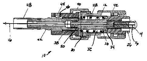
FC type fiber optic connector
Figures 3 to 6 illustrate an adjustable fiber optic connector 10 according to
the present invention
especially adapted for use with an FC type of connector or receptacle.
A ferrule holder 12 presents a counterbore in a distal end section thereof
(right hand side in
Figure 4) for the mounting of any type of FC ferrule 14. The ferrule (high
power version shown) may be
of any type suitable to the end user's purpose.
The high power ferrule concept is presented here as it is often seen in use
with adjustable focus
connector. Note that the fiber 16 is suspended in free space with a protective
ring around it to prevent
accidental damage to the exposed fiber. This design has two features that are
advantageous. With
reference to Figure 5 it is first of all seen that the fiber tip is recessed
by a distance x, only a few microns,
preventing any damage to the fiber should the tip come in contact with a flat
surface. The second is the
presence of a notch 18 in the ring. This notch permits side inspection of the
fiber, and possible access to
the fiber for processes like cleaning, or surface treatment of the fiber.
The proximal end of the ferrule holder 12 (left hand side in Figure 4)
presents a threaded section
20 so it may be threaded into and glued permanently to the lead screw 22.
The outside surfaces of the distal section of ferrule holder 12 define a
polygonal cross-section,
preferably a square section 24 (Figure 6), which passes through a mating hole
in the key frame 26.
A thrust collar 28 surrounds the ferrule holder 12, the thrust collar having a
bottom end wall 30
and, with the outer surface of the ferrule holder 12, defining a generally
annular cavity 32. A radially
outwardly directed flange 34 intermediate the length of the ferrule holder 12
is located adjacent the distal
end of the cavity 32.
4
CA 02574702 2007-01-22
A compression spring 36 is trapped in the generally annular cavity 32 defined
between the
bottom end wall 30 of the thrust collar 28. This spring serves to continuously
provide force on the ferrule
holder/lead screw combination, acting toward the right in Figure 4.
A traveler member 38, which is basically a nut with an internal thread of fine
pitch (80 t.p.i.), is
engaged with an external thread on the lead screw 22. It makes contact with
the external (left hand side)
surface of the thrust collar bottom end wall 30.
A spring guard 40 fits over the traveler 38 and is threaded and permanently
affixed onto the
thrust collar 28.
The key frame 26 and the thrust collar 28 are glued together, confining the
compression spring
34 and ferrule holder 12 inside, and confining an installation or coupling
nut42 outside.
A setscrew 44 is provided for threaded engagement with a threaded bore 46 in
the traveler 38 to
lock the traveler 38 and lead screw 22 together when required.
A crimp sleeve 48 is for cable jacket attachment, and is not considered part
of this device.
Operation:
This male FC connector 10 is installed in the matching female receptacle by
inserting the ferrule
14 into the receptacle "hole", and engaging and tightening the installation
nut 42 onto the external thread
present on the receptacle. The "hole" in the receptacle, manufactured to
suitable tolerances, is a close
match to the diameter of the ferrule 14, and is depended upon to prevent
lateral movement of the ferrule
14. This action is similar to all available FC connector/receptacle matchings.
A key required difference is
that there must not be any stop inside the receptacle. The existence of a stop
would prevent forward
motion of the ferrule.
With conventional fixed-length ferrule designs, no further actions to
facilitate axial (in-out)
movement of the ferrule are available to the user. Since the end plane of the
fiber is at the outside end of
the ferrule, the position of the fiber's end is fixed. The optical coupling
obtained between the fiber end
and the intended optical mate (lens, other fiber end, etc.) inside the
receptacle depends on the
manufacturing control of the ferrule length. Also, no ability to influence the
accuracy of placement of the
optical mate within the receptacle is available to the user of the connector,
and this positioning also
affects coupling efficiency.
In order to effect user control of coupling efficiency, the connector in
question is able to vary the
projection of the ferrule as follows:
Before installation of the connector into the receptacle, the user rotates the
traveler 38
clockwise, which, by virtue of it's thrust upon the thrust collar 28, will
cause the lead screw 22, ferrule
holder 12, ferrule 14, and fiber end to move as a unit to the left,
compressing the spring 36. The moving
items will not rotate, because of the action of the square section of the
ferrule holder in the square hole in
5
CA 02574702 2007-01-22
the key frame 26. The spring 36 will eventually reach the limit of it's
compression (go "solid"). This
condition represents the minimum ferrule projection (fully retracted).
The connector 10 is installed to the receptacle in the conventional manner as
described at the
beginning of this section.
The traveler 38 is then rotated counterclockwise by the user, causing the
ferrule and other
associated parts to move to the right. Thus, by turning the traveler one way
or the other, the user can
make the ferrule move in and out, i.e. change its projection. By conducting
light through the system from
receptacle to connector during the adjustment, the user can measure coupling
efficiency with an optical
power meter, and stop the adjustment when the best coupling is achieved.
Should the user cause a collision to occur between the ferrule end and the
optical mate inside
the receptacle, the force transmitted by the collision is limited by the
compressibility of the spring 36,
preventing damage. Also, in the case of a collision, the user will be notified
by an abrupt decrease in the
turning force required, since the traveler 38 will no longer be contacting the
thrust collar 28. In certain
cases, causing a collision is actually desirable, since this is the position
at which best coupling efficiency
is obtained.
The connector can be locked against further adjustment by tightening the
setscrew 44 installed
in the traveler 38, locking it against the lead screw 22.
When this adjustment procedure has been completed, further adjustment is not
possible without
loosening the setscrew. Accidental adjustment is not possible.
Although the ferrule projection has been set and locked, a further safety
factor exists in the form
of residual spring action availability. If the connector were to be carelessly
installed into any new
situation whereby the existing ferrule projection was too great, and a
collision with the optical mate was
assured, the spring 36 can still limit the collision force, because of the
ability of the traveler 38 to lift clear
of the thrust collar 28.
The subject connector thus allows for adjustable ferrule length and hence the
ability to maximize
optical coupling, and it retains the inherent safety feature of spring
"cushioning" regardless of the length
to which it has been adjusted.
SMA Style Fibre Optic Connector
Referring now to Figures 7 to 9 a connector 50 especially adapted to work with
an SMA type of
connector is illustrated
A ferrule holder 52 presents a counterbore at a distal end thereof (right hand
side in Figure 8)
for the mounting of any type of SMA ferrule 54. The ferrule (high power
version shown) may be of any
type suitable to the end user's purpose.
6
CA 02574702 2007-01-22
At the proximal end of the ferrule holder 52 there is a threaded section 56 so
that it may be
threaded into and glued permanently to a lead screw 58.
A longitudinally extending intermediate section 60 of the ferrule holder 52
presents a polygonal
cross-section, preferably a square section, which passes through a mating
polygonal hole in a proximal
end wall 62 of a thrust collar 64 that generally surrounds the ferrule holder
52. The intermediate section
60 of the ferrule holder 52 and the surrounding thrust collar 64 define
therebetween a generally annular
cavity 66.
A compression spring 68 is trapped in the cavity 66 between the inner surface
or shoulder of the
proximal end wail 62 of the thrust collar 64 and a radially outwardly directed
flange 70 intermediate the
length of the ferrule holder 52 and located generally towards the distal end
of the cavity 66. This spring
serves to continuously provide force on the ferrule holder/lead screw
combination, acting toward the right
in Figure 8.
A traveler 72, which is basically a nut with an internal thread of fine pitch
(80 t.p.i.), is engaged
with an external thread on the lead screw 58. It makes contact with the
external (left hand side) surface
proximal end wall 62 of the thrust collar 64.
A spring guard 74 fits over the traveler 70 and is threaded and permanently
affixed onto the
thrust collar 64.
A nut retainer 76 and stop frame 78 are glued together as at 86 and are glued
to the thrust
collar64, and serve to hold captive the coupling or installation nut 80.
A setscrew 82 is provided for threaded engagement with a threaded bore 84 in
the traveler 72 to
lock the traveler and lead screw together when required.
Operation:
This male SMA connector is installed in the matching female receptacle by
inserting the ferrule
54 into the receptacle "hole", and engaging and tightening the installation
nut 80 onto the external thread
present on the receptacle. The "hole" in the receptacle, machined to suitable
tolerances, is a close match
to the diameter of the ferrule, and is depended upon to prevent lateral
movement of the ferrule. This
action is similar to all available SMA connector/receptacle matchings. A key
required difference is that
there must not be any stop inside the receptacle. The existence of a stop
would prevent forward motion
of the ferrule.
With conventional fixed-length ferrule designs, no further actions to
facilitate axial (in-out)
movement of the ferrule are available to the user. Since the end plane of the
fiber 88 is at the outside
end of the ferrule, the position of the fiber's end is fixed. The optical
coupling obtained between the fiber
end and the intended optical mate (lens, other fiber end, etc.) inside the
receptacle depends on the
manufacturing control of the ferrule length. Also, no ability to influence the
accuracy of placement of the
7
CA 02574702 2007-01-22
optical mate within the receptacle is available to the user of the connector,
and this positioning also
affects coupling efficiency.
In order to effect user control of coupling efficiency, the connector in
question is able to vary the
projection of the ferrule as follows:
Before installation of the connector into the receptacle, the user rotates the
traveler72 clockwise,
which, by virtue of its thrust upon the thrust collar 64, will cause the lead
screw 58, ferrule holder 52,
ferrule 54, and fiber end to move as a unit to the left, compressing the
spring 68. The moving items will
not rotate, because of the action of the square section 60 of the ferrule
holder 52 in the square hole in the
proximal end wall 62 of the thrust collar 64. The spring 68 will eventually
reach the limit of its
compression (go "solid"). This condition represents the minimum ferrule
projection (fully retracted).
The connector is installed to the receptacle in the conventional manner as
described at the
beginning of this section.
The traveler 72 is then rotated counterclockwise by the user, causing the
ferrule and other
associated parts to move to the right. Thus, by turning the traveler 72 one
way or the other, the user can
make the ferrule 54 move in and out, i.e. change its projection. By conducting
light through the system
from receptacle to connector during the adjustment, the user can measure
coupling efficiency with an
optical power meter, and stop the adjustment when the best coupling is
achieved.
Should the user cause a collision to occur between the ferrule end and the
optical mate inside
the receptacle, the force transmitted by the collision is limited by the
compressibility of the spring 68,
preventing damage. Also, in the case of a collision, the user will be notified
by an abrupt decrease in the
turning force required, since the traveler 72 will no longer be contacting the
thrust collar 64. In certain
cases, causing a collision is actually desirable, since this is the position
at which best coupling efficiency
is obtained.
The connector can be locked against further adjustment by tightening the
setscrew 84 installed
in the traveler 72, locking it against the lead screw 58.
When this adjustment procedure has been completed, further adjustment is not
possible without
loosening the setscrew. Accidental adjustment is not possible.
Although the ferrule projection has been set and locked, a further safety
factor exists in the form
of residual spring action availability. If the connector were to be carelessly
installed into any new situation
whereby the existing ferrule projection was too great, and a collision with
the optical mate was assured,
the spring 68 can still limit the collision force, because of the ability of
the traveler 72 to lift clear of the
thrust collar 64.
The subject connector thus allows for adjustable ferrule length and hence the
ability to maximize
optical coupling, and it retains the inherent safety feature of spring
"cushioning" regardless of the length
to which it has been adjusted.
8
CA 02574702 2007-01-22
Other applications of the connector:
Another use of the adjustable connector is for launching light out of a fiber
through a lens to
focus the light. Again the position of the fiber relative to the lens needs
precise adjustment while
minimizing unwanted movement in the other planes. Conventional methods of
moving the lens to focus
the light introduce play, again mainly in the X-Y planes. By using the
adjustable focus connector, with its
precision sleeve, one is able to move the fiber along the Z-axis only, thus
allowing one to change the
position and magnification of the focused spot, while tightly constraining its
position along a single axis.
Figure 10 illustrates a coupler system for effecting laser-to-fiber coupling
utilizing an adjustable
focus connector of the present invention. The system provides a base member
100 having a central
opening or bore 102 in which a lens 104 is mounted. The base member can be
adjusted relative to the
substrate to which it is secured by way of tilt adjustment screws 106 as
described in the aforementioned
US patents of Omur M. Sezerman. A resilient sealing member 108 is positioned
between the base
member and substrate to provide resistance to the adjusting screws and to
hermetically seal the
assembly. A receptacle 110 is secured to the base member 100 and is provided
with a threaded boss
112 projecting from an outer surface thereof. A bore 114 extends through the
boss and receptacle 110
and is axially aligned with the bore 102. The receptacle 110 does not include
any stop against which the
ferrule of the present connector could abut; however, the receptacle may
include a stop face 116 against
which the end face of key frame 26 can abut to assure repeatability in the Z
direction. When the
connector of the present invention has been secured to the receptacle 110 the
adjustment operation
previously described will control the distance between the fiber end and the
lens 104 in the Z direction,
while adjustment of the tilt screw 106 will effect any desired adjustment of
the fiber in X, Y, pitch and yaw.
Figure 11 illustrates a system similar to that shown in Figure 10 for a fiber-
to-fiber coupling
system. The assemblies 120 and 122 are similar to that shown in Figure 10,
with each mounting a lens
124. The base members 126, 128 are adjustable relative to each other by
adjusting screws 130, it being
noted that there is a resilient sealing member 132 positioned between the base
members to provide
resistance to the adjusting screws and to hermetically seal the assembly. At
least one of the optical
fibers secured to the coupling system is adjustably mounted to one of the
receptacles 134 of the base
members as described above with respect to Figure 10. Light from one of the
fibers is collimated by its
lens 124 and then focused into the other fiber by the other lens 124. The
position of the focus spot is
adjusted in the XY plane by the tilt adjustment mechanism of the assembly,
using the screws 130. The
position of the focus spot in the Z direction relative to the fiber pair is
achieved through adjustment of the
adjustable connector as described hereinabove.
Figure 12 shows an optical fiber 140 having a piece of silica 142 fused to the
end thereof,
forming a window or endcap. This allows for high power handling. Light from
the fiber core 144 can then
expand so that when such light reaches the fused silica/air interface 146 the
energy density (W/m2) is
9
CA 02574702 2007-01-22
greatly reduced, minimizing the risk of damage to the fiber. However, the use
of an endcap prevents
utilization of a conventional stop in couplers such as those of the Sezerman
patents, as the location of
the minimum waist no longer coincides with the end of the device. This problem
is rectified when a fiber
with endcap is mounted in an adjustable focus connector of the present
invention since the adjustability
compensates for the different light pattern resulting from the use of an
endcap.