Note: Descriptions are shown in the official language in which they were submitted.
CA 02574936 2007-01-23
WO 2006/041638 PCT/US2005/033901
1
NON-SHORTENING HELICAL STENT
BACKGROUND OF THE INVENTION
The use of stents in bodily lumen is well known. A stent is typically
delivered in an unexpanded state to a desired location in a bodily lumen via a
medical
device such as a catheter. Once the stent is at the desired bodily location,
it is either
expanded with a balloon or other suitable device or allowed to expand by, for
example,
withdrawing a restraining sheath.
Helical or spiral wound stents are generally known, such as disclosed in
US 6042597, the entire disclosure of which is incorporated herein by
reference. Helical
stents may exhibit undesirable effects due to shape changes upon expansion.
For
example, as a helical stent unwinds during expansion, it may experience a
large amount
of foreshortening or reduction in length. Helical stents may also have
relatively large
gaps between windings in an expanded state. In some cases, large gaps may
result in
poor vessel wall support and even tissue prolapse.
There remains a need for helical or wound stents having desirable
flexibility which experience minimal foreshortening upon expansion and provide
suitable
vessel support in an expanded state.
All US patents and applications and all other published documents
mentioned anywhere in this application are incorporated herein by reference in
their
entirety.
Without limiting the scope of the invention a brief summary of some of
the claimed embodiments of the invention is set forth below. Additional
detaiis of the
summarized embodiments of the invention and/or additional embodiments of the
invention may be found in the Detailed Description of the Invention below.
A brief abstract of the technical disclosure in the specification is provided
as well only for the purposes of complying with 37 C.F.R. 1.72. The abstract
is not
intended to be used for interpreting the scope of the claims.
BRIEF SUMMARY OF THE INVENTION
In one embodiment, a helical stent may comprise a helically wound ribbon
of material. The stent may have a longitudinal axis extending therethrough.
The ribbon
CA 02574936 2007-01-23
WO 2006/041638 PCT/US2005/033901
2
may have a longitudinal width as measured in a direction parallel to the
longitudinal axis
of the stent. The longitudinal width of the ribbon in an expanded state of the
stent may
be greater than the longitudinal width of the ribbon in an unexpanded state of
the stent.
In another embodiment, a stent may comprise a helically wound ribbon.
The ribbon may comprise a plurality of turns about a central longitudinal axis
of the
stent. Each turn of the ribbon may have a width. The width of each turn may
increase
upon expansion of the stent.
In another embodiment, a stent may comprise a strip helically wound
about a longitudinal axis of the stent. The strip may have a longitudinal
width as
measured in a direction parallel to the longitudinal axis of the stent and a
predetermined
number of turns about the longitudinal axis. Upon expansion of the stent, the
number of
turns of the strip about the longitudinal axis may decrease and the
longitudinal width of
the strip may increase.
These and other embodiments which characterize the invention are
pointed out with particularity in the claims annexed hereto and forming a part
hereof.
However, for a better understanding of the invention, its advantages and
objectives
obtained by its use, reference should be made to the drawings which form a
further part
hereof and the accompanying descriptive matter, in which there are illustrated
and
described various embodiments of the invention.
BRIEF DESCRIPTION OF THE DRAWINGS
A detailed description of the invention is hereafter described with specific
reference being made to the drawings.
Figure 1 shows an embodiment of a strip or ribbon in an unexpanded
state.
Figure 2 shows an embodiment of a strip of ribbon in an expanded state.
Figure 3 shows an embodiment of a stent comprising a helically wound
ribbon in an unexpanded state.
Figure 4 shows an embodiment of a stent comprising a helically wound
ribbon in an expanded state.
Figure 5 shows another embodiment of a ribbon.
CA 02574936 2007-01-23
WO 2006/041638 PCT/US2005/033901
3
Figure 6 shows another embodiment of a stent comprising a helically
wound ribbon.
Figure 7 shows another embodiment of a strip or ribbon.
Figure 8 shows another embodiment of a strip or ribbon in an unexpanded
configuration.
Figure 9 shows the ribbon of Figure 8 in an expanded configuration.
Figure 10 shows another embodiment of a strip or ribbon.
Figure 11 shows a generic schematic of a stent formed by a helically
wound ribbon.
Figure 12 shows a sectional view of an embodiment of a first rail and a
second rail. The view may be taken along line A-A of Figure 11.
Figure 13 shows another sectional view of an embodiment of a first rail
and a second rail. The view may be taken along line A-A of Figure 11.
Figure 14 shows another sectional view of an embodiment of a first rail
and a second rail. The view may be taken along line A-A of Figure 11.
Figure 15 shows another embodiment of an inventive stent.
Figure 16 shows another embodiment of an inventive stent.
DETAILED DESCRIPTION OF THE INVENTION
While this invention may be embodied in many different forms, there are
described in detail herein specific embodiments of the invention. This
description is an
exemplification of the principles of the invention and is not intended to
limit the invention
to the particular embodiments illustrated.
For the purposes of this disclosure, like reference numerals in the figures
shall refer to like features unless otherwise indicated.
For the purposes of this disclosure, the terms "spiral" and "helical" are
intended to encompass shapes that wind about a longitudinal axis for at least
one turn,
and desirably a plurality of turns. Spiral or helical shapes may include, but
are not limited
to, pure spiral shapes, pure helical shapes, and shapes which may have a
substantially
spiral or helical shape but may also include local derivations from a purely
spiral or
helical shape. Further, in some embodiments, a spiral or helix may include a
non
constant pitch with respect to the longitudinal axis. A pure helix may be a
space curve
CA 02574936 2007-01-23
WO 2006/041638 PCT/US2005/033901
4
with parametric equations x = r sin t; y = Ct; and z= x= r/(r2 + c2); where r
is the
radius of the helix and c is a constant giving the separation of the loops of
the helix.
Figures 1 and 2 show one embodiment of an unwound strip or ribbon 12
which may be wound to form a helical stent. The ribbon 12 may comprise a
framework
having a plurality of cells 14. The ribbon 12 may include a first rail or edge
member 20
and a second rail or edge member 30. In some embodiments, the first rai120 may
be
parallel to the second rail 30. Any portion of the ribbon 12 may have a width
dimension
'w' or spacing between the first rai120 and the second rai130. When the first
rai120 and
second rai130 are parallel, the ribbon 12 may have a constant width w. At
least one and
desirably a plurality of connector struts 40 may connect the first rai120 to
the second rail
30.
It is also within the scope of the invention for the rails to be non-parallel
to one another. In such an embodiment, the width of the ribbon would not be
constant.
The rails may uniformly spiral or may have a substantialy spiral shape with
local
deviations from a pure spiral shape. As an example of the latter, one or more
rails may
have a plurality of peaks and valleys, but may have a shape which is
substantially spiral.
For example, Figure 7 shows an embodiunent of a ribbon 12 wherein the rails
20, 30 have
peaks 66 and valleys 68. The ribbon 12 may be wound helically to form a stent.
Connector struts 40 may be coupled at a first end 42 to the first rai120
and may be coupled at a second end 44 to the second rai130. Connector struts
40 may
include at least one peak 46 and/or at least one valley 48. In some
embodiments, a
connector strut 40 may include a plurality of peaks 46 and a plurality of
valleys 48. The
first end 42 or the second end 44 of a connector strut 40 may extend from a
respective
rai120, 30 in a direction perpendicular to the rai120, 30 or at any non-zero
angle to the
rail20, 30.
Each connector strut 40 may include a connector strut axis 50. A
connector strut 40 may span between the first rai120 and the second rail 30
across the
width of the ribbon 12 or in a direction such that the connector strut axis 50
is generally
perpendicular to the rails 20, 30. In some embodiments, a connector strut 40
may span
between the first rai120 and the second rai130 such that the connector strut
axis 50 is
oriented at an angle to at least one rai120 and/or rai130.
Adjacent connector struts 40 may be similar to one another or may have
CA 02574936 2007-01-23
WO 2006/041638 PCT/US2005/033901
varying geometries. In some embodiments, all of the connector strut axes 50
may be
parallel to one another. In some embodiments, various connector strut axes 50
may be
nonparallel to one another. In some embodiments, one or more connector struts
40 may
be mirror images of other connector struts or may have a reversed orientation
when
5 compared to other connector ~truts. For example, as shown in Fig. 2, a first
connector
strut 56 may be oriented in one direction and may have a peak 46 in proximity
to the first
rai120, while a second connector strut 58 may be oriented in another direction
and may
have a valley 48 in proximity to the first rail 20.
Figure 1 shows an embodiment of an unwound ribbon 12 in a first or
unexpanded state. Figure 2 shows an embodiment of an unwound ribbon 12 in a
second
or expanded state. The length of a ribbon 12 may remain substantially the same
before
and after expansion. Desirably, the width w of a ribbon 12 in an expanded
state is
greater than the width w of the ribbon 12 in an unexpanded state. Upon
expansion of a
ribbon 12, the shape of a connector strut 40 may change and the length of a
connector
strut 40 along its connector strut axis 50 may increase.
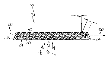
Figures 3 and 4 show embodiments of a ribbon 12 wound helically to
form a stent 10. The ribbon 12 may include any of the features disclosed
herein. The
stent 10 may have a longitudinal axis 60 and may comprise an expandable
framework.
The stent 10 may have a number of ribbon turns 16. Each ribbon turn 16 may
comprise a
portion of the ribbon 12.
The stent 10 may include a gap 18 which may spiral continuously from a
first end 62 of the stent 10 to a second end 64. A gap 18 may comprise space
between
adjacent ribbon turns 16. In some embodiinents, a gap 18 may comprise space
between a
first rail 20 and a second rail 30 that is external to the ribbon 12, wherein
no connector
struts 40 are located.
A gap 18 may spiral for any amount of rotational measurement. For
example, a gap 18 may spiral continuously for 360 , 540 , 720 , 1080 , 4320
or more.
The gap 18 may spiral over less than a complete turn, over a complete turn or
over
integral or non-integral multiples of complete turns.
A ribbon 12 or ribbon turn 16 may further have a longitudinal width 'wl',
as measured in the longitudinal direction of the stent 10. The longitudinal
width wl is the
distance between a first rai120 and a second rai130, as measured in a
direction parallel to
CA 02574936 2007-01-23
WO 2006/041638 PCT/US2005/033901
6
the stent longitudinal axis 60. Generally, the longitudinal width wl of a
ribbon 12 will be
larger than the width w of the ribbon.
Connector struts 40 may be oriented such that a connector strut axis 50 is
at a non-zero angle with respect to the longitudinal axis of the stent 10. In
some
embodiments, at least one connector strut 50 may be oriented such that the
connector
strut axis 50 is parallel to the longitudinal axis of the stent 10.
Figure 3 shows an embodiment of a ribbon 12 wound helically to form a
stent 10 in a first or unexpanded state. The stent 10 may have a predetermined
number
of turns 16, a length and a diameter.
Figure 4 shows an embodiment of a ribbon 12 wound helically to form a
stent 10 in a second or expanded state. Upon expansion, the diameter of the
stent 10
ma.y increase and the number of turns 16 along the length of the stent may
decrease. For
example, an unexpanded stent 10 may have twice as many turns as the stent 10
after
expansion.
Upon expansion of the stent 10, the ribbon 12 may also expand, wherein
the shape of a connector strut 40 may change and the length of a connector
strut 40
along its connector strut axis 50 may increase. Thus, the longitudinal width
wl of the
ribbon 12 or a ribbon turn 18 may increase upon expansion.
Desirably, the overall length of the stent 10 will be substantially similar in
an unexpanded state and in an expanded state.
A ribbon 12 may comprise a plurality of loops 24. Each loop 24 may
have a longitudinal length component, or span in a direction parallel to the
longitudinal
axis of the stent 10. Upon expansion of the stent 10, the longitudinal length
component
of a loop 24 may increase, or a loop 24 may lengthen a direction parallel to
the
longitudinal axis of the stent 10.
Figure 5 shows another embodiment of an unwound strip or ribbon 12
which may be wound to form a helical stent. The width w of the ribbon 12 may
vary
along the length of the ribbon 12. The ribbon 12 may comprise a framework
having a
plurality of cells 14. The ribbon 12 may include a first rail or edge member
20 and a
second rail or edge member 30. A portion of the first rai120 may be parallel
to a portion
of the second rail 30. Any portion of the ribbon 12 may have a width dimension
'w' or
spacing between the first irail 20 and the second rai130. The first rai120 may
include at
CA 02574936 2007-01-23
WO 2006/041638 PCT/US2005/033901
7
least one bend 22 and the second rail 30 may include at least one bend 32. The
first rail
20 may contact the second rail 30 at a first end 52 and at a second end 54 of
the ribbon
12.
Each end of the ribbon 12 may include a tapered portion 38, wherein the
first rail 20 and the second rai130 may be nonparallel. Each end of the ribbon
12 may
taper to a point. Tapered end portions 38 may allow a ribbon 12 to be
helically wound
to form a stent 10 wherein the ends of the stent may be orthogonal to the
longitudinal
axis of the stent 10.
Figure 6 shows an embodinient of a ribbon 12 having tapered end
portions 38 wound helically to form a stent 10. The stent 10 may have a
generally
cylindrical shape. A first end of the stent 62 and a second end of the stent
64 may be
orthogonal to the longitudinal axis of the stent 10.
Figure 7 shows another embodiment of an unwound strip or ribbon 12
which may be wound to form a helical stent. The width w of the ribbon 12 may
vary
along the length of the ribbon 12. The ribbon 12 may comprise a framework
having a
plurality of cells 14. The ribbon 12 may include a first rail or edge member
20 and a
second rail or edge member 30. At least a portion of the first rail 20 may be
parallel to a
portion of the second rail 30.
The ribbon 12 may include at least one end connector 36. An end
connector 36 may connect to an end of a rail 20, 30. In some embodiments, an
end
connector 36 may connect at one end to an end of the first rail 20 and at the
other end to
an end of the second rail 30.
An end connector 36 may extend at any angle with respect to a rai120,
30. In some embodiments, an end connector 36 may include peaks 76 and/or
valleys 78.
In some embodiments, a connector strut 40 may connect to an end connector 36.
A
connector strut 40 may connect to any portion of an end connector 36,
including peaks
76 and valleys 78.
Each end of the ribbon 12 may include a tapered portion 38. Each end of
the ribbon 12 may taper to a point. Tapered end portions 38 may allow a ribbon
12 to be
helically wound to form a stent 10 wherein the ends of the stent may be
orthogonal to the
longitudinal axis of the stent 10.
Figure 8 shows another embodiment of a ribbon 12 which may be wound
CA 02574936 2007-01-23
WO 2006/041638 PCT/US2005/033901
8
to form a stent 10. The ribbon 12 is shown in an unexpanded state. The ribbon
12 may
comprise a framework having a plurality of cells 14. The ribbon 12 may include
a first
rail or edge member 20 and a second rail or edge member 30. In some
embodiments, the
first rai120 may be parallel to the, second rai130. Any portion of the ribbon
12 may have
a width dimension 'w'.
At least one and desirably a plurality of connector struts 40 may connect
the first rail 20 to the second rai130. A connector strut 40 desirably extends
at a non-
zero angle with respect to a rai120, 30.
The ribbon 12 may further include end connectors 36, which may connect
at one end to an end of the first rai120 and at the other end to an end of the
second rail
30. An end connector 36 may include a bend 70, or in some embodiments may
include
curvature and/or an arcuate shape.
Figure 9 shows the ribbon of Figure 8 in an expanded configuration. The
width w in an expanded. configuration is desirably greater than the width w in
an
unexpanded configuration. The connector struts 40 desirably extend from a rail
20, 30 at
a greater angle in the expanded state than in an unexpanded state, up to a
maximum of
90 . For example, in an expanded state, connector struts 40 may extend
orthogonally
with respect to a rai120, 30, while in an unexpanded state, the connector
struts 40 may
extend at an angle of less than 90 .
In some embodiments, end connectors 36 may straighten as the ribbon 12
expands. In some embodiments, the end connectors 36 may extend from a rail 20,
30 at
an angle of less than 90 when the ribbon 12 is expanded.
Figure 10 shows another embodiment of a ribbon 12 which may be
wound helically to form a stent. The ribbon 12 may have a first rail 20 and a
second rail
30. Each rail 20, 30 may have at least one and desirably a plurality of peaks
66 and
valleys 68. Connector struts 40 may connect to any portion of a rai120, 30,
including at
either end, at a peak 66, at a valley 68, or any intermediate location between
a peaks and
a valley.
When a stent 10 includes rails 20, 30 having a plurality of peaks 66 and
valleys 68, the rails 20, 30 may maintain the peaks 66 and valleys 68 during
and after
expansion of the stent 10. However, in some embodiments, upon expansion of the
stent
10, the peaks 66 and valleys 68 may straighten, leaving rails 20, 30 which may
comprise
CA 02574936 2007-01-23
WO 2006/041638 PCT/US2005/033901
9
a pure spiral shape, for example as shown in Figure 4.
When the ribbon 12 of Figure 10 expands, both the length and the width
of the ribbon 12 may increase. Peaks 66 and valleys 68 in each rail 20, 30
allow the
ribbon 12 to lengthen during expansion. The overall length of a stent 10
formed by a
helically wound ribbon 12 may be substantially the same in the unexpanded and
expanded
configurations.
Figure 11 shows a schematic of a ribbon 12 wound to form a stent 10. In
some embodiments, a first rai120 and a second rai130 may be slidably engaged
with one
another when the ribbon 12 is wound helically. Figures 12 - 14 show various
embodiments of mechanisms for engagement between the first rai120 and the
second rail
30. The views of Figures 12 - 14 may be taken from various embodiments of a
stent 10
along line A-A as shown in Figure 11.
Figure 12 shows a sectional detail of an embodiment of a first rail 20 and
a second rai130 which may be slidably engaged. The first rail 20 may include a
first
mating portion 82 and the second rail 30 may include a second mating portion
84. The
first mating portion 82 may engage the second mating portion 84. Desirably,
when the
first mating portion 82 is engaged with the second mating portion 84, the
first rai120
may slide along its longitudinal axis with respect to the second rail 30, but
will not
translocate in directions orthogonal to its longitudinal axis with respect to
the second rail
30. Thus, the first rail 20 may move in a spiral direction with respect to the
second rail
30. In some embodiments, the second mating portion 84 may comprise a shaped
groove,
and the first mating portion 82 may comprise a flange that may be shaped
similarly to the
shaped groove.
In some embodiments, an insulating member 80 may be inserted between
adjacent turns of the stent 10, for example between the first rai120 and the
second rail
30. An insulating member 80 may be used to reduce the possibility of an MRI
artifact
being developed when viewing the stent 10 under MRI. An insulating member 80
may
be made from any suitable material, such as nonconductive material. Some
examples
include ceramics, non-conductive polymers, poor conductors, latex, rubber,
silicon
rubber, Pebax(V, urethane, pelothane, Tecothane , polyester isobutyl styrene,
epoxies
and thermoplastics. When the first rai120 is shaped to engage the second rail
30, at least
a portion of the insulating member 80 may be placed between the first mating
portion 82
CA 02574936 2007-01-23
WO 2006/041638 PCT/US2005/033901
and the second mating portion 84.
Figure 13 shows a sectional detail of another embodiment of a first rai120
and a second rai130 which may be slidably engaged. The first rail 20 may
include a first
mating portion 82, and the second rai130 may include a second mating portion
84. The
5 rails 20, 30 may further include an incremental adjustment mechanism which
may prevent
sliding of the rails with respect to one another unless a predetermined amount
of force is
applied to the rails 20, 30. In one embodiment, an incremental adjustment
mechanism
may comprise a series of grooves 86 in the second rail 30 and at least one
detent 88 in
the first rail 20. The detent 88 may incrementally move between adjacent
grooves 86 as
10 the stent 10 expands. In another embodiment, each rail 20, 30 may include a
plurality of
shaped teeth 90, which may be oriented in opposite directions, which are
arranged to
allow incremental movement of the first rail 20 with respect to the second
rai130. An
incremental adjustment inechanism may be desirable for embodiments of a stent
10 that
are balloon expandable or at least partially balloon expandable.
Figure 14 shows another embodiment of a first rai120 engaged with a
second rail 30. A gap connector 94 may connect at one portion to the first
rail 20 and at
another portion to the second rai130. A gap connector 94 may be located in a
gap 18
between the first rai120 and the second rai130. Desirably, a gap connector 94
is
arranged to lengthen as the first rail 20 translocates with respect to the
second rail 30.
Therefore, a gap connector 94 may include a plurality of peaks and valleys. A
gap
connector 94 may limit movement of the first rail 20 with respect to the
second rail 30 in
stent longitudinal and/or radial directions.
Figure 15 shows another embodiment of a stent 10, wherein a first
portion 26 of the stent 10 may coinprise a helically wound ribbon 12 as herein
described,
and a second portion 28 may comprise an alternative stent design, such as a
prior art
design. For example, the first portion 26 may comprise a first rai120, a
second rai130
and a plurality of connector struts 40. The second portion 28 may comprise a
plurality
of serpentine bands 34, wherein adjacent serpentine bands 34 may be connected
by
connectors 35. The first portion 26 and the second portion 28 may be connected
to one
another using a connector 92 or any other suitable method. A connector 92 may
connect
at one end to the first portion 26 and at another end to the second portion
28. A
connector 92 may connect to any part of the first portion 26, such as a rail
20, 30 or a
CA 02574936 2007-01-23
WO 2006/041638 PCT/US2005/033901
11
connector strut 40. In some embodiments, multiple connectors 92 may connect a
first
portion 26 to a second portion 28.
Figure 16 shows another embodiment of a stent 10, wherein a first
portion 26 and a second portion 96 may each comprise a helically wound ribbon
12 as
herein described. The ribbon 12 of the first portion 26 may wind in one
direction, and
the ribbon of the second portion 96 may wind in another direction. The first
portion 26
may connect to the second portion 96 at a joining area 98, wherein the first
rai120a of
the first portion may 26 connect to the first rai120b of the second portion
96, and the
second rai130a of the first portion 26 may connect to the second rai130b of
the second
portion 96. The joining area 98 may also include one or more common connector
struts
41, which may extend from a rail 20, 30 of the first portion 26 to a rai120,
30 of the
second portion 96.
In some embodiments, a first portion 26 and a second portion 96 may be
connected to one another via one or more connectors 92 (see Figure 15). A
connector
92 may connect at one end to any part of a first portion 26, and may connect
at the other
end to any part of a second portion 96.
In other embodiments, a stent 10 may comprise any number of individual
portions, such as described with respect to Figures 15 and 16 (i.e. portions
26, 28, 96,
etc.), connected in series. Adjacent portions may be connected by one or more
connectors 92, by a joining area 98, or by any other suitable method. A stent
10 may
comprise a long stent having a plurality of portions. The portions may be
arranged in
any desirable configuration. The portions may have any suitable shape and
orientation
with respect to one another. Various embod'unents may be self-expanding or
balloon
expandable.
In some embodiments, a helically wound ribbon 12 stent may be used as a
portion of a multilayer stent. The helically would ribbon 12 stent may be used
in parallel
with any other type of stent configuration. For example, the helically wound
ribbon stent
may comprise an inner stent, and a prior art design stent may comprise an
outer stent. In
another embodiment, a prior art design stent may comprise an inner stent, and
a helically
wound ribbon stent may comprise an outer stent. In some embodiments, a
helically
would ribbon 12 stent may comprise an inner stent and another helically would
ribbon 12
stent may comprise an outer stent. The inner ribbon 12 stent may wind in one
direction,
CA 02574936 2007-01-23
WO 2006/041638 PCT/US2005/033901
12
and the outer ribbon 12 stent may wind in another direction.
The inventive stents 10 may have a substantially uniform diameter in the
expanded and/or unexpanded states or may have a non-uniform diameter in the
expanded
and/or unexpanded state. Thus, for example, a portion of the stent 10 may have
a
continuous or a discontinuous taper in diameter. One or both of the ends of
stent may
have a wider diameter than the remainder of the stent or a narrow diameter.
The stent
may also have a generally increasing diameter from one end to the other.
In some embodiments, a stent 10 or ribbon 12 may include a closed cell
14 design. In some embodiments, a stent 10 or ribbon 12 may include at least
on open
cell or a plurality of open cells.
In some embodiments, a stent 10 may be self-expanding, formed from a
shape memory material, spring steel or other materials which are capable of
self-
expanding. Examples of shape memory materials are provided below. Desirably,
the
stent 10 may self-expand to an expanded configuration. The stent 10 may be
reduced to
an unexpanded state and covered with a sheath or other constraining device.
Desirably,
in an unexpanded state, a ribbon 12 may be constrained to have an unexpanded
width
that is less than the width of the ribbon 12 in an expanded state. Upon
removal of the
sheath or constraining device, the stent 10 may self-expand to an expanded
configuration.
In some embodiments, a stent 10 may be balloon expandable. In some
embodiments, a stent 10 may be a combination balloon expandable/self-expanding
stent,
such as a stent comprising a portion of plastically deformable material and a
portion of
shape memory material.
Suitable medical devices such as those disclosed in US 6,123,712, US
6,120,522 and US 5,957,930 may be used to deliver the inventive stents to the
desired
bodily location. The choice of delivery device will depend on whether a self-
expanding
or balloon expandable stent is used. The inventive stents may be delivered in
conjunction
with one or more stent retaining sleeves or socks. Examples of stent retaining
sleeves
are disclosed in US 20030065376A1, US 6,607,552, and US 6,432,129, the entire
disclosures of which are incorporated herein by reference.
Upon delivery to a deployment site, an inventive stent may be expanded,
wherein the diameter of the stent may increase and the width of the ribbon may
increase.
CA 02574936 2007-01-23
WO 2006/041638 PCT/US2005/033901
13
The inventive stents may be manufactured using known stent
manufacturing techniques. A stent may be formed by first forming a ribbon 12
and then
helically winding the ribbon 12 to form a stent. A stent may also be formed
directly in a
tubular shape such as by performing manufacturing operations on a tube of
material. For
example, a framework having first and second rails and connector struts may be
cut
directly from a tube.
Suitable methods for manufacturing the inventive stents include laser
cutting, laser ablating, chemical etching or stamping of a tube. The inventive
stents may
also be manufactured by laser cutting, laser ablating, chemically etching, or
stamping a
flat sheet, rolling the sheet and, optionally, welding the sheet. Other
suitable
manufacturing techniques include electrode discharge machining or molding the
stent
with the desired design. The stent may also be manufactured by welding
individual
sections together, for example by welding connector struts 40 to the first
rai120 and to
the second rail 30. Any other suitable stent manufacturing process may also be
used.
Any suitable stent material may be used in the manufacture of the
inventive stents. Examples of such materials include polymeric materials,
metals,
ceramics and composites. Suitable polymeric materials include therznotropic
liquid
crystal polymers (LCP's), shape memory polymers, bioabsorbable polymers and
the like.
Where the stent is made of metal, the metal may be stainless steel,
bioabsorbable alloys,
cobalt chrome alloys such as elgiloy, tantalum or other plastically deformable
metals.
Other suitable metals include shape-memory metals such as nickel-titanium
alloys
generically known as "nitinol", platinum/tungsten alloys and titanium alloys
and spring
steel.
The invention also contemplates the use of more than one material in the
inventive stents. For example, the connector struts 40 may be made from a
different
material than the first rai120 or second rail 30. Some connector struts 40
inay be made
from different materials than other connector struts. Further, any individual
member,
such as a rail or connector strut, may be made from more than one material,
and may
include a first portion made from a first material and a second portion made
from a
second material.
The inventive stents may be provided in mechanically expandable form, in
self-expanding form or as a hybrid of the two. Mechanically expandable stents,
in
CA 02574936 2007-01-23
WO 2006/041638 PCT/US2005/033901
14
accordance with the invention, may be expanded using any suitable mechanical
device
including a balloon and/or a catheter having one portion rotatable with
respect to another
portion. For example, a helically wound stent may be expanded using a catheter
having a
first portion connected to the first end of the stent and a second portion
connected to the
second end of the stent. The two portions may be rotated with respect to one
another to
cause an unwinding of the helical stent and a resulting increase in the stent
diameter.
The inventive stents may include suitable coatings or markers to enhance
visibility under fluoroscopy, MRI or the like. For example, the stents may be
coated with
gold or other noble metals or sputtered with tantalum or other metals. The
stents may
also be made directly from a radiopaque material to obviate the need for a
radiopaque
coating or may be made of a material having a radiopaque inner core. Other
radiopaque
metals which may be used include platinum, platinum-tungsten, palladium,
platinum-
iridium, rhodium, tantalum, or alloys or composites of these metals. In the
case of MRI
compatible stents, the stent will desirably be made of an MRI compatible
material, as
known in the art and optionally may be provided with MRI markers as known in
the art.
In some embodiments the stent 10 may comprise one or more therapeutic
agents. In some embodiments the agent is placed on the stent in the form of a
coating.
In at least one embodiment the coating includes at least one therapeuticagent
and at least
one polymer agent.
A therapeutic agent may be a drug or other pharmaceutical product such
as non-genetic agents, genetic agents, cellular material, etc. Some examples
of suitable
non-genetic therapeutic agents include but are not limited to: anti-
thrombogenic agents
such as heparin, heparin derivatives, vascular cell growth promoters, growth
factor
inhibitors, Paclitaxel, etc. Where an agent includes a genetic therapeutic
agent, such a
genetic agent may include but is not limited to: DNA, RNA and their respective
derivatives and/or components; hedgehog proteins, etc. Where a therapeutic
agent
includes cellular material, the cellular material may include but is not
Iimited to: cells of
human origin and/or non-human origin as well as their respective components
and/or
derivatives thereof. Where the therapeutic agent includes a polymer agent, the
polymer
agent may be a polystyrene-polyisobutylene-polystyrene triblock copolymer
(SIBS),
polyethylene oxide, silicone rubber and/or any other suitable substrate.
CA 02574936 2007-01-23
WO 2006/041638 PCT/US2005/033901
In some embodiments, a stent may be provided with dimpled surfaces,
holes, valleys and/or other indentations in order to hold a coating, such as a
drug coating.
The inventive stents may also be provided with a sugar or more generally
a carbohydrate and/or a gelatin to maintain the stent on a balloon during
delivery of the
5 stent to a desired bodily location. Other suitable compounds for treating
the stent
include biodegradable polymers and polymers which are dissolvable in bodily
fluids.
Portions of the interior and/or exterior of the stent may be coated or
impregnated with
the compound. Mechanical retention devices may also be used to maintain the
stent on a
balloon or catheter during delivery. To that end, the use of other coatings on
the
10 inventive stents is also within the scope of the invention.
The inventive stents may also be used as the framework for a graft.
Suitable coverings include nylon, collagen, PTFE and expanded PTFE,
polyethylene
terephthalate and KEVLAR, or any of the materials disclosed in US 5,824,046
and US
5,755,770:= More generally, any known graft material may be used including
synthetic
15 polymers such as polyethylene, polypropylene, polyurethane, polyglycolic
acid,
polyesters, polyamides, their mixtures, blends and copolymers.
The above disclosure is intended to be illustrative and not exhaustive.
This description will suggest many variations and alternatives to one of
ordinary skill in
this field of art. All these alternatives and variations are intended to be
included within
the scope of the claims where the term "comprising" means "including, but not
limited
to". Those fainiliar with the art may recognize other equivalents to the
specific
embodiinents described herein which equivalents are also intended to be
encompassed by
the claims.
Further, the particular features presented in the dependent claims can be
combined with each other in other manners within the scope of the invention
such that
the invention should be recognized as also specifically directed to other
embodiments
having any other possible combination of the features of the dependent claims.
For
instance, for purposes of claim publication, any dependent claim which follows
should be
taken as alternatively written in a multiple dependent form from all prior
claims which
possess all antecedents referenced in such dependent claim if such multiple
dependent
format is an accepted format within the jurisdiction (e.g. each claim
depending directly
from claim 1 should be alternatively taken as depending from all previous
claims). In
CA 02574936 2007-01-23
WO 2006/041638 PCT/US2005/033901
16
jurisdictions where multiple dependent claini forma.ts are restricted, the
following
dependent claims should each be also taken as alternatively written in each
singly
dependent claim format which creates a dependency from a prior antecedent-
possessing
claim other than the specific claim listed in such dependent claim below.
This completes the description of the invention. Those skilled in the art
may recognize other equivalents to the specific embodiment described herein
which
equivalents are intended to be encompassed by the claims attached hereto.