Language selection

Search

Patent 2575089 Summary

Third-party information liability

Some of the information on this Web page has been provided by external sources. The Government of Canada is not responsible for the accuracy, reliability or currency of the information supplied by external sources. Users wishing to rely upon this information should consult directly with the source of the information. Content provided by external sources is not subject to official languages, privacy and accessibility requirements.

Claims and Abstract availability

Any discrepancies in the text and image of the Claims and Abstract are due to differing posting times. Text of the Claims and Abstract are posted:

  • At the time the application is open to public inspection;
  • At the time of issue of the patent (grant).
(12) Patent Application: (11) CA 2575089
(54) English Title: SHOCK ABSORBER
(54) French Title: AMORTISSEUR
Status: Deemed Abandoned and Beyond the Period of Reinstatement - Pending Response to Notice of Disregarded Communication
Bibliographic Data
(51) International Patent Classification (IPC):
  • F16F 9/54 (2006.01)
  • B60G 15/00 (2006.01)
  • F16F 9/32 (2006.01)
(72) Inventors :
  • DAVIS, MARK (Canada)
(73) Owners :
  • MARK DAVIS
(71) Applicants :
  • MARK DAVIS (Canada)
(74) Agent: DOUGLAS B. THOMPSONTHOMPSON, DOUGLAS B.
(74) Associate agent:
(45) Issued:
(22) Filed Date: 2007-01-17
(41) Open to Public Inspection: 2008-07-17
Availability of licence: N/A
Dedicated to the Public: N/A
(25) Language of filing: English

Patent Cooperation Treaty (PCT): No

(30) Application Priority Data: None

Abstracts

English Abstract


A shock absorber includes a first body having an internal cavity. A first
mounting is
provided on the first body. An elongated second body is telescopically
received within the
internal cavity of the first body. Dampening means are positioned within the
internal cavity
of the first body and adapted to dampen telescopic movement of the second body
relative to
the first body. A second mounting is provided on the second body. The second
mounting is a
slot adapted to receive a mounting pin. The slot defines a free travel limit
for the mounting
pin. Movement of the mounting pin within the slot caused by vibrations and
oscillations does
not energize the dampening means unless such movement exceeds the free travel
limit
defined by the slot.


Claims

Note: Claims are shown in the official language in which they were submitted.

4
What is Claimed is:
1. A shock absorber, comprising:
a first body having an internal cavity;
a first mounting on the first body;
an elongated second body telescopically received within the internal cavity of
the first
body;
dampening means positioned within the internal cavity of the first body and
adapted
to dampen telescopic movement of the second body relative to the first body;
a second mounting on the second body, the second mounting being a slot adapted
to
receive a mounting pin; the slot defining a free travel limit for the mounting
pin, such that
movement of the mounting pin within the slot caused by vibrations and
oscillations does not
energize the dampening means unless such movement exceeds the free travel
limit defined by
the slot.
2. The shock absorber as defined in Claim 1, wherein the dampening means is
one of a
pneumatic dampening medium, a hydraulic dampening medium or a mechanical
dampening
medium.

Description

Note: Descriptions are shown in the official language in which they were submitted.


CA 02575089 2007-01-17
1
TITLE:
Shock absorber
FIELD
The present invention relates to a shock absorber, such as may be used with a
vehicle
wheel.
BACKGROUND
Shock absorbers are presently subject to continuous "chatter" caused by
vibrations
and oscillations. When used with a vehicle wheel, this chatter reduces the
smoothness of the
ride as experience by an occupant of a vehicle. This same chatter diminishes
the effectiveness
of the shock absorber in other applications.
SUMMARY
There is provided a shock absorber which includes a first body having an
internal
cavity. A first mounting is provided on the first body. An elongated second
body is
telescopically received within the internal cavity of the first body.
Dampening means are
positioned within the internal cavity of the first body and adapted to dampen
telescopic
movement of the second body relative to the first body. A second mounting is
provided on
the second body. The second mounting is a slot adapted to receive a mounting
pin. The slot
defines a free travel limit for the mounting pin. Movement of the mounting pin
within the slot
caused by vibrations and oscillations does not energize the dampening means
unless such
movement exceeds the free travel limit defined by the slot.
BRIEF DESCRIPTION OF THE DRAWINGS
These and other features will become more apparent from the following
description in
which reference is made to the appended drawings, the drawings are for the
purpose of
illustration only and are not intended to in any way limit the scope of the
invention to the
particular embodiment or embodiments shown, wherein:
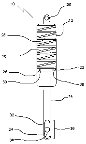
THE FIGURE is a side elevation view in section of a shock absorber.
DETAILED DESCRIPTION

CA 02575089 2007-01-17
2
A shock absorber generally identified by reference numeral 10, will now be
described
with reference to THE FIGURE.
Structure and Relationship of Parts:
A shock absorber 10 is detailed in THE FIGURE. Shock absorber 10 has a first
body
12, an elongated second body 14, and a dampening means. First body 12 has an
internal
cavity 18 and a first mounting 20. First mounting 20 may be attached to the
frame (not
shown) of a vehicle. Elongated second body 14 is telescopically received
within internal
cavity 18 of first body 12. Elongated second body 14 has a first end 22 and a
second
mounting 24. First end 22 may function like a piston 26 within internal cavity
18. The
dampening means is shown more particularly taking the form of a spring 28
which is
positioned within internal cavity 18. Spring 28 is connected to both internal
cavity 18 and
first end 22 of elongated second body 14. Spring 28 is adapted to dampen
telescopic
movement of elongated second body 14 relative to first body 12. In the
embodiment shown,
spring 28 is contained with internal cavity 18, internal cavity 18 being
filled with hydraulic
fluid. Alternatively, spring 28 could be attached to first body 12 and second
mounting, such
that spring 28 would be function outside of internal cavity 18. First end 22
contains fluid ports
30 that allow hydraulic fluid to flow through first end 22. Alternatively,
other conventional
dampening means may be used. The most common conventional dampening means
include
pneumatic dampening medium (gas shocks), hydraulic dampening medium (hydraulic
shocks) or mechanical dampening medium (metal springs, rubber springs). Second
mounting
24 is a slot 32, adapted to receive a mounting pin 34. Slot 32 defines a free
travel limit 36 for
mounting pin 34. Mounting pin 34 may be attached, directly or indirectly to
the wheels (not
shown) of a vehicle.
Operation:
When vehicle is at rest, mounting pin 34 will tend to descend to the bottom of
slot 32
by force of gravity. However, during operation of the vehicle the operation of
shock absorber
10 will result in mounting pin 34 being centrally positioned. Slot 32 allows
mounting pin 34
a certain amplitude of movement within free travel limit 36 before elongated
second body 14
is forced to move relative to first body 12. This means that movement of
second body 14
relative to first body 12 will not be required for most minor bumps,
oscillations and

CA 02575089 2007-01-17
3
vibrations. Fluid ports 30 allow hydraulic fluid to flow through first end 22
of elongated
second body 14 when elongated second body 14 is forced to move relative to
first body 12.
Although a shock absorber has been illustrated that has an internal spring, it
will be
appreciated that M shock absorber may be converted in accordance with the
teachings of the
present invention, regardless of the dampening means used. Once the vibrating
suspension
pin establishes an upper and lower travel, for example plus or minus 1 cm, the
pin will hold
its centred position within those travel limits. This reduces "road rumble"
considerably, yet
still dampen any dangerous jolt, vibration, or oscillation that exceeds the
travel limits.
In this patent document, the word "comprising" is used in its non-limiting
sense to
mean that items following the word are included, but items not specifically
mentioned are not
excluded. A reference to an element by the indefinite article "a" does not
exclude the
possibility that more than one of the element is present, unless the context
clearly requires that
there be one and only one of the elements.
It will be apparent to one skilled in the art that modifications may be made
to the
illustrated embodiments without departing from scope of the Claims.

Representative Drawing
A single figure which represents the drawing illustrating the invention.
Administrative Status

2024-08-01:As part of the Next Generation Patents (NGP) transition, the Canadian Patents Database (CPD) now contains a more detailed Event History, which replicates the Event Log of our new back-office solution.

Please note that "Inactive:" events refers to events no longer in use in our new back-office solution.

For a clearer understanding of the status of the application/patent presented on this page, the site Disclaimer , as well as the definitions for Patent , Event History , Maintenance Fee  and Payment History  should be consulted.

Event History

Description Date
Time Limit for Reversal Expired 2010-01-18
Application Not Reinstated by Deadline 2010-01-18
Deemed Abandoned - Failure to Respond to Maintenance Fee Notice 2009-01-19
Application Published (Open to Public Inspection) 2008-07-17
Inactive: Cover page published 2008-07-16
Inactive: IPC assigned 2008-07-10
Inactive: Adhoc Request Documented 2008-01-02
Revocation of Agent Request 2007-11-16
Appointment of Agent Request 2007-11-16
Inactive: First IPC assigned 2007-11-08
Inactive: IPC assigned 2007-11-08
Application Received - Regular National 2007-02-21
Filing Requirements Determined Compliant 2007-02-21
Inactive: Filing certificate - No RFE (English) 2007-02-21

Abandonment History

Abandonment Date Reason Reinstatement Date
2009-01-19

Fee History

Fee Type Anniversary Year Due Date Paid Date
Application fee - small 2007-01-17
Owners on Record

Note: Records showing the ownership history in alphabetical order.

Current Owners on Record
MARK DAVIS
Past Owners on Record
None
Past Owners that do not appear in the "Owners on Record" listing will appear in other documentation within the application.
Documents

To view selected files, please enter reCAPTCHA code :


To view images, click a link in the Document Description column. To download the documents, select one or more checkboxes in the first column and then click the "Download Selected in PDF format (Zip Archive)" or the "Download Selected as Single PDF" button.

List of published and non-published patent-specific documents on the CPD .

If you have any difficulty accessing content, you can call the Client Service Centre at 1-866-997-1936 or send them an e-mail at CIPO Client Service Centre.


Document
Description 
Date
(yyyy-mm-dd) 
Number of pages   Size of Image (KB) 
Drawings 2007-01-17 1 10
Claims 2007-01-17 1 21
Description 2007-01-17 3 114
Abstract 2007-01-17 1 17
Representative drawing 2008-06-25 1 5
Cover Page 2008-07-04 2 36
Filing Certificate (English) 2007-02-21 1 157
Reminder of maintenance fee due 2008-09-18 1 112
Courtesy - Abandonment Letter (Maintenance Fee) 2009-03-16 1 172
Correspondence 2007-02-21 1 53
Correspondence 2007-11-16 5 123
Correspondence 2008-09-18 1 38
Correspondence 2009-03-16 1 92