Note: Descriptions are shown in the official language in which they were submitted.
CA 02575448 2007-01-29
WO 2006/017502 PCT/US2005/027417
DENTAL IMPRESSION TRAYS
CROSS REFERENCE
[0001] This application claims the benefit of U.S.
provisional patent application No. 60/598,339, filed August
2, 2004, entitled "Dental Impression Trays", the content of
which is hereby expressly incorporated by reference in its
entirety.
FIELD OF THE INVENTION
[0002] The present invention relates to dental impression
trays for taking dental impressions of a subject in general.
Specifically, the present invention relates to dental
impression trays known as triple bite trays.
BACKGROUND OF THE INVENTION
[0003] Triple bite trays or triple trays are well known
in the dental art for taking impressions of patients'
dentitions. Triple trays are so coined for their ability to
simultaneously capture the upper and lower impressions and
the bite registration of a subject during a same dental
procedure.
[0004] While triple trays are popular among
practitioners, some conventional triple trays have problems
with distortion. Distortion, as can be expected, is
undesirable because it results in an incorrect mold of the
subject's dentition, which then leads to an incorrect model
of the dentition made by pouring, for example, plaster into
the incorrect mold.
[0005] Accordingly, there is a need for triple trays with
greater resistance to distortion.
SUMMARY OF THE INVENTION
1
CA 02575448 2007-01-29
WO 2006/017502 PCT/US2005/027417
[0006] The present invention may be implemented by
providing a triple tray for taking an impression of a
dentition including an inner wall, an outer wall having a
handle attached thereto, and a screen connected to both the
inner wall and the outer wall and defining at least one
channel; a plurality of ribs disposed along at least one
surface of the outer wall and at least one surface of the
inner wall; and wherein the handle includes a dimple defined
by a tapered ramp having a tapered surface having a radially
outwardly incline from a flat portion of the handle towards
a periphery of the handle.
[0007] In one aspect, the plurality of ribs are disposed
along at least one of an inner wall surface of the outer
wall and the inner wall surface of the inner wall for
facilitating gripping by an impression material.
[0008] The present invention may also be practiced by
providing a triple tray for taking an impression of a
dentition including an inner wall, an outer wall having a
handle attached thereto, and a screen connected to both the
inner wall and the outer wall; a plurality of ribs disposed
along at least one of an inner wall surface of the outer
wall and the inner wall surface of the inner wall for
facilitating gripping by an impression material; wherein a
plurality of openings separate the inner wall surface of the
inner wall from an outer wall surface of the inner wall, a
plurality of lateral walls connected to both the inner wall
surface and the outer wall surface of the inner wall,
separating one opening from another opening, and wherein the
handle includes a dimple defined by a ramp comprising an
inclined surface extending adjacent a periphery of the
handle.
[0009] The present invention further provides a triple
tray for taking an impression of a dentition including a
metal frame having a first elongated portion, a curved
2
CA 02575448 2007-01-29
WO 2006/017502 PCT/US2005/027417
portion, a second elongated portion, and a post attached to
a plastic handle having a first retaining wall, a receiving
bore, and a dimple defined by a ramp including an incline
extending along a periphery of the handle, wherein the post
is received in the receiving bore and wherein a screen is
attached to the first elongated portion, the curved portion,
and the second portion of the metal frame to define an upper
channel and a lower channel.
[0010] In one embodiment, the first retaining wall may
include a plurality of ribs disposed along an inner wall
surface of the wall for facilitating gripping by an
impression material.
[0011] In another embodiment, at least a portion of the
first elongated portion may include a polymeric sleeve.
[0012] In one aspect, at least a portion of the first
elongated portion may be over-molded with a polymeric
sleeve. In another aspect, at least a portion of the first
elongated portion may be enclosed by the polymeric sleeve.
[0013] In one embodiment, at least a portion of the first
elongated portion may be secured to a second retaining wall.
In one aspect, the second retaining wall may include a
plurality of ribs disposed along at least a portion of an
inner wall surface of the retaining wall.
[0014] Other aspects and advantages of the present
invention may be understood and practiced by reviewing the
following description and the figures appended hereto.
BRIEF DESCRIPTION OF THE DRAWINGS
[0015] These and other features and advantages of the
present invention will become appreciated as the same become
better understood with reference to the specification,
claims and appended drawings wherein:
3
CA 02575448 2007-01-29
WO 2006/017502 PCT/US2005/027417
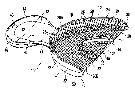
[0016] FIG. 1 is a semi-schematic perspective view of a
full arch tray provided in accordance with aspects of the
present invention;
[0017] FIG. la is a semi-schematic perspective view of
the full arch tray of FIG. 1 shown with alternative ribbing
configuration;
[0018] FIG. 2 is a semi-schematic end view of the full
arch tray of FIG. 1 without the screen for clarity;
[0019] FIG. 3 is a semi-schematic side view of the full
arch tray of FIG. 1;
[0020] FIG. 4 is a semi-schematic perspective view of a
three-quarter tray provided in accordance with aspects of
the present invention;
[0021] FIG. 5 is a semi-schematic plan view of the tray
of FIG. 4;
[0022] FIG. 6 is a semi-schematic perspective view of an
anterior tray provided in accordance with aspects of the
present invention;
[0023] FIG. 6A is a semi-schematic top view of the
anterior tray of FIG. 6 without the screen at the rear
channel;
[0024] FIG. 7 is a semi-schematic perspective view of a
posterior tray provided in accordance with aspects of the
present invention;
[0025] FIG. 7a is a perspective view of the non-metal
portion of the tray of FIG. 7;
[0026] FIG. 7b is a perspective view of a sleeve portion
of the tray of FIG. 7;
[0027] FIG. 7c is a perspective view of the metal portion
of the tray of FIG. 7c;
[0028] FIG. 8 is a semi-schematic perspective view of the
tray of FIG. 7 from a different perspective;
4
CA 02575448 2007-01-29
WO 2006/017502 PCT/US2005/027417
[0029] FIG. 9 is a semi-schematic plan view of the tray
of FIG. 7;
[0030] FIG 10 is a perspective view of the handle without
a bore; and
[0031] FIG. 11 shows a perspective view of an embodiment
of a posterior tray of the present invention; and
[0032] FIG. 12 shows a top view of the tray of FIG. 11 of
the present invention.
DETAILED DESCRIPTION
[0033] The detailed description set forth below in
connection with the appended drawings is intended as a
description of the presently exemplified embodiments of a
triple tray provided in accordance with practice of the
present invention and is not intended to represent the only
forms in which the present invention may be constructed or
utilized. The description sets forth the features and the
steps for constructing and using various triple trays of the
present invention in connection with the illustrated
embodiments. It is to be understood, however, that the same
or equivalent functions and structures may be accomplished
by different embodiments that are also intended to be
encompassed within the spirit and scope of the invention.
Also, as denoted elsewhere herein, like element numbers are
intended to indicate like or similar elements or features.
[0034] Impressions of patients' teeth may be produced for
a variety of purposes such as the manufacture of appliances
for bite registrations, crown and bridge constructions, and
the like. The present invention includes various types of
impression trays adapted for use by a dentist for specific
applications. These tray types may include a posterior, an
anterior, a full arch, a three-quarter arch and a quadrant
tray. The tray may be used simply as a carrier for an
impression-forming material and to facilitate the placing
CA 02575448 2007-01-29
WO 2006/017502 PCT/US2005/027417
and removal of the impression material in and from a
patient's mouth.
[0035] In use, the tray is filled with a pliable, uncured
composite such as a silicone impression material or a
polyether impression material and is seated in a patient's
mouth until the material sets or cures. This generally takes
a few minutes' time.
[0036] The impression tray of the present invention
provides sufficient rigidity to produce a good impression by
minimizing distortion of the impression when the material
laden tray is removed from a patient's mouth. An accurate
negative impression of the tooth or teeth selected for a
dental procedure may then be used to form an accurate
duplicate of the patient's dentition, following which a
dental appliance may be produced on a stone model or
similar.
[0037] In one embodiment, as exemplified in FIG. 1, where
a semi-schematic perspective view of a full arch dental
impression tray is provided in accordance with aspects of
the present invention. The tray 10, as shown, is s full arch
tray, useful for taking a full dentition of a patient's
mouth, and is, for example, symmetrical about the parting
line L. The tray 10 includes a buccal wall or outer wall
12, a lingual wall or inner wall 14, a screen 16
interconnecting the two walls, and a handle 18 attached to
the outer wall 12. The inner and outer walls define a
channel 20 for receiving a curable impression material
adapted for biting down by a patient to capture the
patient's dentition. As is readily apparent, impression
material may be applied to the channel 20 on both the top
channel 20A and the bottom channel 20B. Any suitable
impression material, including those already in the market
or disclosed in prior art, for example, alginate, polyvinyl
6
CA 02575448 2007-01-29
WO 2006/017502 PCT/US2005/027417
siloxane, polyether, and super-hydrophilic VPS, just to name
a few, may be used with the tray 10.
[0038] The screen 16 acts as a retaining base for the
impression material and may be made of any non-woven
material or weaved material that is sufficiently thin to
minimize the likelihood of obstructing a patient teeth
during full occlusion and to not impede the making of an
accurate bite on the impression material, i.e., to not
prevent the upper and lower teeth from meeting. In one
exemplary embodiment, the screen may be made of any woven or
any non-woven material, for example, spun-bound polyester,
having, for example, an average thickness of about 2.5 mil
(. 06 mm) to about 5.5 mil (. 15 mm) , and more for example,
from about 3.5 mi l (.09 mm) to about 4.5 mi l (.11 mm). An
example of a woven material may be a cotton gauze, available
from Poon Cheung Kee Cotton Factory in China, a nylon mesh
material or other equivalent materials. Examples of non-
woven material may include those disclosed in U.S. Pat. Nos.
3,853,659; 4,340,563; 4,405,297; 4,692,106; and 5,431,986,
and made commercially available from Cerex Advanced Fabrics
of Cantonment, Florida. The contents of these patents are
expressly incorporated herein by reference as if disclosed
in full.
[0039] The outer wall 12 includes an outer wall surface
22 and an inner wall surface 24. A plurality of ribs 26
adorns the inner wall surface 24 of the outer wall 12. The
plurality of ribs 26 provides surfaces for the curable
impression material to adhere or attach to so that the same
does not shift or separate from the tray during the
impression procedure and helps to minimize distortion. In
one exemplary embodiment, the ribs 26 may be substantially
evenly-spaced along the inner surface 24 of the outer wall
12 and each rib may include rounded ends 28. In another
7
CA 02575448 2007-01-29
WO 2006/017502 PCT/US2005/027417
embodiment, the ribs 26 may be irregularly or randomly
spaced along the inner surface 24 of the outer wall 12.
[0040] In one exemplary embodiment, the plurality of ribs
26 may be generally of substantially the same height with
the exception of the ribs near the edge or ends 30 of the
outer wall 12, which may be made successively shorter to
correspond with the, for example, tapered portions of the
two ends of the outer wall 12 if present. The ends 30 of
the outer wall 12 may be tapered to minimize or prevent
injuries to the gingival areas of the mouth when the tray is
used to take an impression of the subject's dentition.
[0041] The inner wall 14 includes an inner wall surface
32 and an outer wall surface 34. In one embodiment, a
plurality of ribs 26 may also adorn the wall of the inner
wall surface 32, also for facilitating gripping or adhesion
by the curable impression material. In one aspect, the ribs
26 may also have rounded ends and may be substantially
evenly-spaced along the inner wall surface 32 of the inner
wall 14. A plurality of elliptical openings 36 separate the
inner wall surface 32 from the outer wall surface 34. The
lateral walls 38 between the openings 36 may function as
ribs to increase rigidity of the inner wall 14, and help to
minimize distortion. The openings 36 may vary in size,
shape, and number, provided that a sufficient number and/or
wall thickness are incorporated for rigidity. A rear
channel 40, defined by the arcuate inner wall 14 and the
screen 16, is not intended to hold, although may hold,
curable impression material but rather to add to the
structural rigidity of the tray 10 along the radial
direction.
[0042] In other embodiments, such as that shown in FIG.
la, the ribs 26 may be present in a substantially
longitudinal direction 106, a substantially transverse
direction 108, and combinations thereof. In the FIG. la
8
CA 02575448 2007-01-29
WO 2006/017502 PCT/US2005/027417
embodiment, only a few representative ribs in various rib
configurations are shown for clarity although it is readily
recognized that an array of spaced apart ribs in various
configurations may be incorporated. In other embodiments,
at least one of the ribs 106, 110 may be located
substantially centrally along the outside surface 22 of the
outside wall 12 and the outside surface 34 of the inner wall
14, substantially proximate the parting line L. In still
further embodiments, at least one of the ribs 112 may also
be present along the outer edge of at least one of the inner
surface 32 of the inner wall 14, the outer surface 34 of the
inner wall 14, the inner surface 24 of the outer wall 12,
and the outside surface 22 of the outer wall 12. As noted
above, the ribs, whether present in vertical or horizontal
configuration, may contribute to added stiffness of the tray
so that the walls may be constructed sufficiently thin
without compromising the desired stiffness of the tray.
[0043] In one embodiment, at least one rib may adorn the
upper and lower edges of the outer wall surface 22 of the
outer wall 12, and the upper and lower edges of the outer
wall surface 34 of the inner wall 14, in lieu of or addition
to the plurality of ribs 26 present on the inner surface 24
of the outer wall 12 and the inner surface 32 of the inner
wall 14.
[0044] In still another embodiment, at least one rib 114
adorns the outer wall surface 22 of the outer wall 12, and
the outer wall surface 34 of the inner wall 14, along the
longitudinal direction of the walls, in lieu of or in
addition to the plurality of ribs 26 present on the inner
surface 24 of the outer wall 12 and the inner surface 32 of
the inner wall 14.
[0045] In still a further embodiment, at least one rib
may adorn the outer wall surface 22 of the outer wall 12,
and the outer wall surface 34 of the inner wall 14
9
CA 02575448 2007-01-29
WO 2006/017502 PCT/US2005/027417
substantially centrally along the parting line L of the
walls. Even though the ribs have been described in detailed
with respect to the full arch above, they are equally
applicable to the other arches described below.
[0046] The oversized handle 18 may be, for example,
attached or integrally molded to the outer wall surface 22
of the outer wall 12. The handle 18 includes a base 41,
which extends from the outer wall surface 22 of the outer
wall, and a dimple 42 which may be formed by incorporating a
ramp 44 along the periphery 46 of the handle 18, and may,
for example, resemble an amphitheatre. The dimple generally
makes the tray easier to grip. In another example, the ramp
44 includes an arcuate section that has a tapered width
extending along the periphery 46 of the handle in a
generally U-shaped configuration. The tapered section
originates at about the flat section 48 of the handle 18 and
inclines as it extends radially outwardly. The ramp 44
facilitates gripping of the tray 10 by a user and the
inclined section of the ramp provides a physical barrier for
gripping by the user. As is readily apparent, an identical
ramp 44 may be provided on the second side of the handle 18.
In another exemplary embodiment, the ramp may have an
incline of about 3 to about 30 degrees from horizontal. In
an exemplary embodiment, the ramp 44 has a non-linear
incline or a curved incline. An optional bore 43 for
hanging the tray 10 or through which a tag or label (not
shown) having personal identification and/or other personal
information of the patient may be inserted may be included.
[0047] The base section 41 of the handle 18 is, for
example, sufficiently large to further add to the structural
rigidity of the outer wall 12. In an exemplary embodiment,
the base section 41, at the point of attachment with outer
wall 12, includes a width equivalent to about 10% to about
30% of the arc surface of the outer wall 14. The handle may
CA 02575448 2007-01-29
WO 2006/017502 PCT/US2005/027417
also be provided with a writable surface on a portion
thereof for recording the personal information of a patient.
The writable portion may be raised, indented or flush with
the rest of the handle. The portion is generally of the same
material as the rest of the handle. It may also be
separately treated or coated for better writability, i.e.,
for recording information.
[0048] In one exemplary embodiment, to construct a tray
with minimal flex or distortion when the patient bites
down on the curable impression material, the tray 10 may be
made from any polymer including a polystyrene (such as
STYRONTM 685D, or STYRONTM A-TECHT"", available form Dow
Chemical Company); a polyolefin such as polyethylene,
polypropylene, and polybutylene; a polyester such as
polyethylene terephthalate, or polybutylene terephthalate; a
polyamide, such as Nylon 66w; an acrylic polymer;
polyvinylchloride; polyetherimide like ULTEM ; a
polycarbonate or polycarbonate (PC) blends such as a
polymeric alloy like Xenoy resin, which is a composite of
polycarbonate and polybutyleneterephthalate or Lexan
plastic, which is a copolymer of polycarbonate and
isophthalate terephthalate resorcinol resin (all available
from GE Plastics); other rigid materials including
polyformaldehyde (available as DELRIN ),
polyaryletheretherketone (PEEK), polyphenylene sulphide,
acrylonitrile butadiene styrene (ABS), polyacetals; liquid
crystal polymers, such as an aromatic polyester or an
aromatic polyester amide containing, as a constituent, at
least one compound selected from the group consisting of an
aromatic hydroxycarboxylic acid (such as hydroxybenzoate
(rigid monomer), hydroxynaphthoate (flexible monomer), an
aromatic hydroxyamine and an aromatic diamine, (exemplified
in U.S. Patent Nos. 6,242,063, 6,274,242, 6,643,552 and
6,797,198, the contents of which are incorporated herein by
11
CA 02575448 2007-01-29
WO 2006/017502 PCT/US2005/027417
reference), polyesterimide anhydrides with terminal
anhydride group or lateral anhydrides (exemplified in U.S.
Patent No. 6,730,377, the content of which is incorporated
herein by reference) or combinations thereof.
[0049] In addition, any polymeric composite such as
engineering prepregs or composites, which are polymers
filled with pigments, carbon particles, silica, glass
fibers, conductive particles such as metal particles or
conductive polymers; or mixtures thereof may also be used.
For example, a blend of polycarbonate and ABS (Acrylonitrile
Butadiene Styrene), a mixture of polyamides, such as nylon
66w and fiberglass material, may be used.
[0050] In an exemplary embodiment, the wall thickness of
the outer wall 12 and the inner wall 14 may be, for example,
about 1/32" (about .8 mm) to about 1/4" (about 6 mm) thick,
more for example, about 1/16" (about 1.5 mm) to about 1/5"
(about 5 mm).In general, the combination of ribs, their
location and arrangement, the thickness of the walls as well
as the type of material used in their construction, all may
contribute to the desired stiffness. Thus, if the ribs are
strategically located, the material choice may not be as
critical, and polymers and composites including polymers
such as polyethylene terephthalate, polybutylene
terephthalate, polystyrene, or polypropylene, maybe used in
the construction of the trays. In fact, if the ribs are
strategically located, the thickness of the walls may
actually be decreased without compromising the rigidity. In
addition, a combination of different materials and
composites may be used in making different components of the
tray, such as making the outer wall 12 from one material and
the inner wall 14 from a composite. Also, the thickness of
the walls may not be uniformly across the wall. In one
embodiment, the wall may also be tapered towards the edges.
12
CA 02575448 2007-01-29
WO 2006/017502 PCT/US2005/027417
[0051] In one exemplary embodiment, the tray 10 may be
made by co-molding the inner wall 14, the outer wall 12, and
the handle 18 with the screen 16. In another exemplary
embodiment, the tray 10 may be made from a separate upper
tray part 50 and lower tray part 52 and snap-fit together
along the centerline L via a plurality of detent
engagements. In a further embodiment, the tray 10 may be
made from a separate upper tray part 50 and lower tray part
52 and attached together using heat seal or an adhesive.
[0052] Referring now to FIG. 2, an end view of the tray
looking from the perspective of the rear channel 40 of
the outer wall 14 towards the inner wall surface 24 of the
outer wall 12 is shown, without the screen 16 for clarity.
As can be seen, the wall dimension or height measured from
the parting line L for the inner wall 14 may be different
than the wall dimension measured from the parting line L for
the outer wall 12. The outer wall 12 is higher or greater
than the inner wall 14 as shown, and as the patient bites
down on the curable impression material, the curable
material may not flow extra-orally or outside of the mouth.
However, some amount of over flow of curable impression
material flowing from the main channel 20 into the rear
channel 40 when an impression is taken may occur.
[0053] Although not shown, the tray 10 may be made
proportionately smaller for taking the full dentition of a
smaller person or made larger for a larger person.
[0054] Referring now to FIG. 3, a side view of the tray
10 is shown. In one exemplary embodiment, the handle 18
includes a width at its rear section 54 that is larger than
the width at its neck section 41. As is readily apparent to
a person of ordinary skill in the art, the added width is
due to the additional width of the tapered wall section or
ramp 44. In comparison to the width of the outer wall 12,
the width at the rear section 54 has a width that is, for
13
CA 02575448 2007-01-29
WO 2006/017502 PCT/US2005/027417
example, about 20% to about 50% of the width of the outer
wall, more for example, about 25% to about 35%. The width
at the neck section 41 is, for example, about 10% to about
40% of the width of the outer wall, more for example, about
15% to 25%.
[0055] Without wishing to be bound to a theory, it is
surmised that the wide handle, for example, the width of the
neck section of the handle, may also contribute to the
rigidity of the trays to minimize distortion of any
impressions made.
[0056] Referring now to FIG. 4, a three quarter tray 56
(herein 3/4-tray) for taking 3/4 of a dentition is shown.
The 3/4-tray 56 is similar to the full arch tray 10
described above with reference to FIGs. 1-3 with the
exception that a portion of the outer wall 60 and the inner
wall 62 on one side of the plane defined by the centerline
of the handle 18, along the lengthwise direction, have been
reduced or shortened. The 3/4 tray 56 may be configured to
take an impression of an entire one side of the upper and
lower teeth and through the first bicuspid of the other side
of the upper and lower teeth, thus so named 3/4 tray. Thus,
the amount or portion of the outer and inner walls to be
shortened to make the 3/4 tray is dependent on the amount of
tray necessary to take an impression of an entire one side
of the dentition and through the first bicuspid of the other
side of the teeth. A bigger person may also need a bigger
3/4 tray than a smaller person. The outer wall 60 and inner
wall 62 of the 3/4 tray 56 may have points that
substantially terminate or align along a linear line 58
defined by the edge of the screen 16.
[0057] Referring now to FIG. 5, a top plan view of the
3/4 tray 56 of FIG. 4 is shown. In an exemplary embodiment,
the base section 41, at the point of attachment with outer
wall 60, includes a width equivalent to, for example, about
14
CA 02575448 2007-01-29
WO 2006/017502 PCT/US2005/027417
25% to about 45% of the arc surface of the outer wall 60.
The handle 18 is otherwise the same as the handle of FIGs.
1-3 and includes a amphitheatre or dimple 42, defined by the
ramp 44. In one exemplary embodiment, the end or tip 64 of
the outer wall 60 at the shortened side of the wall may also
be tapered, as shown in FIG. 4, in the same manner as the
taper shown in FIG. 1.
[0058] Referring now to FIG. 6, an anterior tray 66 for
taking an impression of the anterior (incisor and cuspid)
portion of a patient's dentition is shown. The anterior
tray 66 is similar to the full arch tray 10 described above
with reference to FIG. 1, except that the wall portions of
the outer wall 68 and the inner wall 70 do not extend as far
from the origin 72 or tip of the inner and outer walls. The
arc length of the inner and outer walls 68, 70, may extend
from the origin 72 a sufficient amount to enable coverage of
the anterior portion of the patient's dentition. In one
exemplary embodiment, the handle 18 is of the same size and
configuration as the handle of FIGs. 1-3. here again, a
bigger size may be needed for a bigger person and a smaller
size for a smaller person.
[0059] FIG. 6A is a semi-schematic top plan view of the
anterior tray 66 of FIG. 6. In the figure shown, the screen
16 is absent from the rear channel 40, which may be an
alternative method for practicing the triple trays including
comprising a rear channel of the present invention.
[0060] FIG. 7 is an isometric view of a posterior tray 74
for taking an impression of the posterior (bicuspid and
molar) portion of a patient's dentition. In the orientation
shown, the tray 74 is designed to take an impression of the
posterior portion of the right side of the patient's
dentition. By turning the same tray 74 upside-down, it may
be used to take an impression of the left side of the
patient's dentition.
CA 02575448 2007-01-29
WO 2006/017502 PCT/US2005/027417
[0061] The tray 74 may be a hybrid in that it may include
portions made from plastic and portions made from metal.
The plastic portion or portions may include any of the above
mentioned polymer or polymeric composites, for example,
polystyrene or a composite such as nylon 66w with 40% by
weight fiberglass. The metal portion or portions may be of
any light weight metal having structural integrity, and may
include, but not limited to aluminum; stainless steel;
magnesium or its alloys; brass; copper; an alloy such as
Ni/Ti alloy; any amorphous metals including those available
from Liquid Metal, Inc. or similar ones, such as those
described in U.S. Patent No. 6,682,611, and U.S. Patent
Application No. 2004/0121283, the entire contents of which
are incorporated herein by reference, or combinations
thereof.
[0062] The metal portion may include an elongated U-
shaped frame 76, which has a first elongated portion 78, a
curved portion 80, and a second elongated portion 82
including a post 84, as shown in FIGs 7 and 7c. The curve
portion 80 of the frame 76, for example, may include a flat
portion or surface having a width sufficiently thin to fit
between the gums behind the second or third molars when bit
down by a subject.
[0063] The polymeric portion of the tray 74, as shown in
FIGs. 7 and 7a, may include a handle portion 18, a receiving
bore 86, and a retaining wall 88, which, in the presently
exemplified embodiment, may include a single integrally cast
or molded piece or separately cast or molded parts and then
assembled into one piece. In one exemplary embodiment, the
retaining wall 88 may include a first section 90 adjacent
the handle 18 and a second section 94 opposite the first
section 90. The first section 90 includes a tapered edge
which may taper from a central portion 92 of the retaining
wall 88 towards the substantially flat section 48 of the
16
CA 02575448 2007-01-29
WO 2006/017502 PCT/US2005/027417
handle 18. The second section 94 includes a curved corner
adapted for helping to eliminate or minimize sharp edges
that may otherwise cause discomfort to the user of the tray
74. In one exemplary embodiment, the wall 88 may also be
slightly curved to correspond to the posterior portion of
the dentition.
[0064] The U-shaped frame 76 may be assembled to the
handle 18 by inserting the post 84 into a receiving bore 86
of the plastic handle 18. The post 84 and the receiving
bore 86 may incorporate detents for a secured connection.
Alternatively, the post 84 may be secured to the receiving
bore 86 using glue or adhesive. In another embodiment, the
U-shaped frame and the handle 18 may be integrally molded,
for example, by over-molding a polymeric sleeve over
portions of the U-shaped metal frame.
[0065] In one embodiment, the first elongated portion 78
of the U-shaped frame may be covered with a polymeric
portion 78a, as shown in FIGs. 11 and 12, or uncovered, as
shown in FIG. 7, 8 or 9.
[0066] FIG. 7c shows a perspective view of the U-shaped
frame 76 prior to its attachment to the polymeric portion of
the tray. In an exemplary embodiment, the frame 76 is hollow
and may have a slit or a channel 96 extending the length of
the interior surface of the frame 76. The screen 16 may be
then placed in the slit 96 and pinched down to secure the
screen to the frame. In an alternative embodiment, the
frame 76 may include a core such that the frame is not
hollow or is coreless.
[0067] FIG. 7b'shows a perspective view of a polymeric
sleeve 78a including a bore 78b throughout its length for
fitting around the first elongated portion 78 of the U-
shaped frame 76, shown in FIG. 7c. As noted above, the arch
78a may be formed separately from the U-shaped frame and
then assembled afterwards onto at least a portion of the
17
CA 02575448 2007-01-29
WO 2006/017502 PCT/US2005/027417
first elongated portion 78, or it may be integrally molded,
for example, over-molded onto at least a portion of the
first elongated portion 78 of the U-shaped frame 76. The
assembled structures are exemplified in FIGs 11 and 12.
[0068] The outer arch 78a may also include a retaining
wall 78c, which is exemplified as an integrally cast or
molded piece, as shown in Fig. 7b. In one embodiment, the
retaining wall 78c may be tapered towards at least one of
the ends.
[0069] FIG. 11 shows a perspective view of one embodiment
of the posterior tray which may have structures similar to
those described above, for example, in FIG. 7. In addition,
at least a portion of the first elongated portion 78 is
covered with a polymeric sleeve 78a. The sleeve 78a may be
integrally molded to the first elongated portion 78 and has
a retaining wall 78c, as mentioned above, in one embodiment.
In another embodiment, the sleeve 78 may be=separately
constructed with a retaining wall 78c, and a bore 78b
throughout its length, through which the first elongated
portion 78 may be inserted.
[0070] FIG. 12 shows the top view of the embodiment of
FIG. 11. In the orientation shown, the retaining wall 88 is
shown to have a curvature that matches the curvature of the
second elongated section 94 of the U-shaped frame 76. In
one exemplary embodiment, the retaining wall 88 is not
physically attached to the U-shaped frame 76 or the second
elongated section 94 of the U-shaped frame. In another
exemplary embodiment, the retaining wall 88 may incorporate
means for attaching the second portion 94 or the central
portion 92 of the wall to the frame 76. Such means include
glue, adhesive, or detents.
[0071] In this embodiment, the screen material 16, which
may be woven or non-woven, as noted above, may be attached
or bounded to the posterior tray only about the polymeric
18
CA 02575448 2007-01-29
WO 2006/017502 PCT/US2005/027417
portion 82 and the polymeric sleeve 78a. A hole may be
present towards the free end of the polymeric sleeve 78a,
adapted for receiving a hanging label (not shown), having a
patient's vital information.
[0072] In one exemplary embodiment, the handle 18 may
include a dimple section 42 defined by the ramp 44, as
previously discussed.
[0073] Referring now to FIG. 8, the screen 16 is shown to
be attached to the U-shaped frame 76. In an exemplary
embodiment, the frame 76 is hollow and may have a slit or a
channel 96 extending the length of the interior surface of
the frame 76, as discussed above in FIG. 7c. The screen 16
may be then placed in the slit 96 and pinched down to secure
the screen to the frame. In an alternative embodiment, the
frame 76 may include a core such that the frame is not
hollow or is coreless.
[0074] In one exemplary embodiment, the retaining wall 88
similarly may include a gap or a slit 98 along at least a
portion of its centerline. The screen 16 slides between the
slit* 98 when the U-shap.ed frame 76 is assembled to the
handle 18 by inserting the post 84 into the receiving bore
86 of the handle 18. Similar to the other tray embodiments
discussed elsewhere herein, the retaining wall 88 includes a
plurality of spaced-apart ribs 26.
[0075] FIG. 9 is a top view or plan view of the posterior
tray 74. In the orientation shown, the retaining wall 88 as
shown has a curvature that matches the curvature of the
second elongated section 94 of the U-shaped frame 76. In
one exemplary embodiment, the retaining wall 88 is not
physically attached to the U-shaped frame 76 or the second
elongated section 94 of the U-shaped frame. In another
exemplary embodiment, the retaining wall 88 may incorporate
means for attaching the second portion 94 or the central
19
CA 02575448 2007-01-29
WO 2006/017502 PCT/US2005/027417
portion 92 of the wall to the frame 76. Such means include
glue, adhesive, or detents.
[0076] In one exemplary embodiment, the handle 18
includes a dimple section 42 defined by the ramp 44, as
previously discussed. However, the base section 41 of the
handle 18 may be slightly narrower than the handle any may
incorporate the receiving bore 86. Overall, the tray 74 may
be sized so that the posterior portion of a subject's
dentition may be taken. The tray 74, and other trays
discussed elsewhere herein, may incorporate a silver, white,
blue, or red finish or other colors to be determined during
manufacturing of the tray. A tray may also be used with a
bigger person, and a smaller tray may be used with a smaller
person, as noted before.
[0077] The U-shaped frame 76 may be made of any metal or
metallic alloy, as discussed above. In one embodiment, the
U-shaped frame may be made from a flattened wire, which may
be formed by using any impact forces such as coining or
stamping. The flattened wire has an added advantage of
having smooth surfaces for patient comfort even if the
polymeric sleeve 78a is absent from the construction. In
another embodiment, the U-shaped frame may be cast or
molded. In a further embodiment, the U-shaped frame may be
machined. In some embodiments, the metallic parts may have
to be de-burred to minimize any sharp edges.
[0078] As with the description of the ribs, the
description of other tray parts, such as the handle 18 and
the different materials that may be used to mold the tray,
with respect to the full arch is equally applicable to all
the other arches and embodiments described elsewhere herein.
Also, although the exemplified embodiments of the invention
have been described with some specificity, the description
and drawings set forth herein are not intended to be
delimiting, and persons of ordinary skill in the art will
CA 02575448 2007-01-29
WO 2006/017502 PCT/US2005/027417
understand that various modifications may be made to the
embodiments discussed herein without departing from the
scope of the invention, and all such changes and
modifications are intended to be encompassed within the
appended claims. Various changes to the triple trays
described elsewhere herein may be made including changes to
the size of the tray, the number of ribs, the spacing of the
ribs, the slope or taper of various structures, the absence
of a bore on the handle, such as shown in FIGs. 7a, 10 and
11, and the type of screen to be used. Accordingly, many
alterations and modifications may be made by those having
ordinary skill in the art without deviating from the spirit
and scope of the invention.
21