Note: Descriptions are shown in the official language in which they were submitted.
CA 02575487 2007-01-25
STENT DELIVERY SYSTEM TO IMPROVE PLACEMENT
ACCURACY FOR SELF-EXPANDING STENT
FIELD OF THE INVENTION
The present invention generally relates to medical devices, particularly a
stent
delivery system for a self-expanding stent that is provided with structure
that prevents
stent jumping during deployment.
BACKGROUND OF THE INVENTION
A stent is a generally longitudinal tubular device formed of biocompatible
material(s) that is useful in the treatment of stenoses, strictures or
aneurysms in blood
vessels and other body vessels. Stents can be implanted within an unhealthy
vessel to
reinforce collapsing, partially occluded, weakened, or abnormally dilated
sections of
the vessel. Typically, stents are employed after angioplasty of a blood vessel
to
prevent restenosis of the diseased vessel. While stents are most notably used
in blood
vessels, stents may also be implanted in other body vessels such as the
urogenital tract
and the bile duct. A stent may exhibit flexibility to allow it to be inserted
through
curved vessels. Furthermore, stents are often initially configured in a
radially
compressed state, such as by crimping, to facilitate delivery and deployment
in
intraluminal catheter implantation.
Stents are akin to scaffoldings in their support of the passageway.
Structurally,
a stent may have two or more struts or wire support members connected together
into
a lattice-like frame. As indicated, stents may be in a compressed state prior
to delivery
and deployment, as compression facilitates insertion through small cavities.
Stents can
be delivered to the desired implantation site percutaneously in a catheter or
similar
transluminal device. With a lattice-like structure, a portion of the stent
surface area is
open, such openings defined by the struts that form the stent. Open spaces are
desirable in that they allow plaque from the lesion to fall through the stent
and enter
the blood stream.
-1-
CA 02575487 2007-01-25
Carotid artery stenting is becoming a more prevalent option in treating
carotid
artery diseases (stenosis). In carotid artery stenting procedure, a relatively
small stent
of about 8-10 mm diameter and about 20 mm long may be used. A stent may be
configured as an elongate structure, generally cylindrical in shape. The stent
may exist
in a first, pre-deployed state. The stent can be transformed into a second
state, post
delivery, with the stent, in the second state, having a substantially greater
diameter
than the diameter of the stent in the first state. The stent can be implanted
in the vessel
of a patient using the stent delivery system appropriate for the type of stent
being
delivered to the vessel.
Certain kinds of stents are self expanding, and other kinds, such as the
Palmaz-
Schatz stent, available from Cordis Corporation of Miami Lakes, FL, USA, are
expanded radially outward by the force imparted by an inflated angioplasty
type
balloon as it pushes against the inner stent walls. An example of a self-
expanding stent
is the SMARTS nitinol stent, a nickel titanium alloy stent also available from
the
Cordis Corporation.
Typically, a stent may be delivered in an introducer sheath. The stent and
sheath can be advanced to a site within the patient's vessel through a guide
catheter. A
self-expanding stent possesses a spring force that causes the stent to expand
following
its implacement in the vessel when a restraining sheath is retracted from the
compressed stent. Alternatively, and by way of example, a self-expanding
nitinol stent
may be of the kind that expands when warmed above the martensitic transition
temperature for the nitinol alloy (e.g., above 30 C.)
Self-expanding stent delivery systems (SDS) are provided with an outer sheath
into which the stent is loaded. The distal end of the outer sheath member is
retracted
toward the proximal end of the SDS in order to deploy a self-expanding stent.
Because the outer sheath may develop slack, the inner member and tip of the
stent
Delivery System (SDS) tend to move forward when the outer member is pulled
back.
2
CA 02575487 2007-01-25
Upon deployment, a self-expanding stent expands row by row as the
surrounding outer sheath is retracted. In a successful deployment, the
initially
expanded rows of the stent should anchor to the vessel wall to set the
position of the
stent. Rows that expand subsequently will then expand outward and contact the
vessel
wall.
In a successful deployment the stent is positioned at the desired location
within
the vessel. However, self-expanding stents exhibit spring-like
characteristics, so care
must be taken to reduce, if not eliminate, the phenomenon of "stent jumping".
That is,
self-expanding stents can store energy. Frictional force generated as the
outer sheath
is retracted can cause the stent perform like a spring, storing energy as the
frictional
force acts on the stent. The stored energy is released as the stent expands
beyond the
end of the sheath, and this release of energy can cause the stent to move or
"jump"
from the desired position, resulting in inaccurate placement. Inaccurate stent
placement could render stent deployment as ineffective in treating stenosis.
Accordingly, it is desirable to provide a device that minimizes, if not
eliminates, stent jumping in order to provide for more accurate placement of
self-
expanding stents.
SUMMARY OF THE INVENTION
The improvement of stent placement accuracy is an object of the invention.
The minimization, if not the elimination, of stent jumping is a further object
of
the invention.
The present invention is directed to a stent delivery system for the delivery
of a
self-expanding stent that is provided with structure that facilitates accurate
stent
deployment at the desired location. This arrangement is intended to diminish
stent
jumping, if not eliminate it, which as indicated above adversely affects stent
deployment.
In accordance with the present invention, a stent delivery stent delivery
system
(SDS) for a self-expanding stent is provided. The stent delivery system has an
outer
3
CA 02575487 2007-01-25
sheath forming an elongated tubular member having distal and proximal ends and
an
inside and outside diameter. The stent delivery system also includes an inner
shaft
located coaxially within the outer sheath. The inner shaft has a distal end, a
proximal
end and a longitudinal axis extending therebetween. The stent delivery system
is
configured to retain a self-expanding stent located within the outer sheath,
wherein the
stent makes frictional contact with the outer sheath and the shaft is disposed
coaxially
within a lumen of the stent. The SDS is further provided with structure that
upon
release and deployment improves stent placement accuracy and reduces, if not
eliminates, stent jumping. In one aspect of the invention, the structure is
positioned
distal to the position on the delivery device where the stent is retained. For
example
the structure can be positioned intermediate the location where the stent is
retained
prior to its deployment and the distal end of the delivery device.
Alternatively, the
structure may be positioned along the guide wire at a location distal to the
delivery
device. Preferably, the structure may be an off-center support member that
initially is
retained in a non deployed state within a lumen, which for example could be
the outer
sheath of the SDS which also retains the stent, it may be the distal tip of
the SDS.
Further, regardless of where the off center support member may be located on
the
SDS, it is advantageous to engage same to the SDS in a non-coaxial manner. In
other
words, upon expansion, the axis of the off center support member is not
coaxial with
the inner shaft of the device, for reasons that will become apparent below.
In an exemplary arrangement, the off center support member is retained within
the outer sheath and is mounted non-coaxially to the inner shaft. When the
outer
sheath is retracted in the stent deployment process, the off center support
member,
which in one inventive aspect is made of an expandable, spring like material,
expands
at an orientation that is not coaxial, relative to the longitudinal axis of
the device. The
off center support member expands to the interior vessel wall and makes
contact with
same. The vessel walls apply a counterforce to the interior shaft of the SDS,
forcing
the SDS into an off-center arrangement within the vessel. Now, with the SDS in
the
4
CA 02575487 2013-07-17
off center arrangement, and further sheath retraction, the self-expanding
stent is
exposed. This arrangement causes initial off-center deployment of the stent,
which is
believed to facilitate the anchoring of the stent to the walls of the vessel.
Thus, the
structural attributes of the present delivery system should reduce, if not
eliminate, the
stent jumping effect that is believed to result in inaccurate stent
deployments.
In an alternative embodiment, the off center support member is a vascular
device, such as a vascular filter or thrombectomy/embolectomy device, in which
a
blood permeable sac having a support loop forming a rim around the open end of
the
sac. The support hoop can be attached to the distal region of the stent
delivery system
or other elongated member, such as a guide wire. When deployed and open, the
support hoop defines an opening in the sac.
BRIEF DESCRIPTION OF THE DRAWINGS
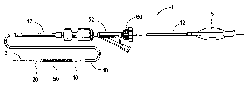
Figure 1 is a simplified elevational view of a stent delivery system in that
can
be modified in accordance with the present invention;
Figure 2 depicts a cross sectional view through a vessel wall of an embodiment
of a stent delivery system of the present invention;
Figure 3 depicts a cross sectional view through a vessel wall of another
embodiment of a stent delivery system of the present invention;
Figure 4 is a cross sectional view of an aspect of the embodiment shown in
Fig. 3.
DETAILED DESCRIPTION OF THE INVENTION
The structural attributes of the present invention, which facilitate an
initial off
center stent deployment, may be incorporated into existing stent delivery
systems. For
that reason, the features of the stent delivery systems disclosed in U.S.
Patent nos.
6,773,446 and 6,939,352, each of which share the common assignee with the
present
application, are examples of stent delivery systems that can be modified to
include the
off centering structural attributes within the ambit of this disclosure.
However, the
present invention need not be bound to the
5
CA 02575487 2007-01-25
specific features and embodiments of these particular patent disclosures. In
any event,
Figure 1 illustrates a conventional stent delivery system of the kind
disclosed in U.S.
Patent no. 6,773,446.
FIG. 2 shows a self-expanding stent delivery stent delivery system 1 made in
accordance with the present invention in the course of deployment within a
body
vessel 5, such as a blood vessel. Stent delivery system 1 comprises inner and
outer
coaxial tubes, wherein the inner tube is identified as shaft 10 and the outer
tube is
identified as the sheath 40. A self-expanding stent 50 is located within the
outer
sheath, wherein (at least prior to deployment) the stent makes frictional
contact with
the outer sheath. As seen in Fig. 1, shaft 10 is disposed coaxially within a
lumen of the
stent.
At the distal end of the shaft, the shaft 10 has distal tip 20 attached
thereto.
Distal tip 20 can be made from any number of materials known in the art
including
polyamide, polyurethane, polytetraflouroethylene, and polyethylene, in multi-
layer or
single layer structures. The distal tip 20 has a near end 34 whose diameter
can
approximate that of the outer diameter of the sheath 40 adjacent to the distal
tip.
Furthermore the distal tip tapers to a smaller diameter from its proximal end
34 to its
distal end 36. A guide wire 3 passing out of the delivery device is used to
guide the
device to the stent deployment site during navigation through the vessel
passages.
Specifically as shown, the distal tip 36 can be hollow to give the distal end
of the tip
the ability to slide over and therefore be directed by the guide wire 3.
Shaft 10 is provided with marker 22. In an aspect of the invention, the marker
22 is located distal to the stent bed 24, that is, the place where the stent
is retained on
the delivery device prior to its deployment. Marker 22 can be made from any
number
of materials, such as stainless steel, and is even more preferably made from a
highly
radio-opaque material such as platinum, gold, tantalum, or radio-opaque filled
polymer. The marker can be attached to shaft 10 by mechanical or adhesive
bonding,
6
CA 02575487 2007-01-25
or by any other means known to those skilled in the art. Stent 50 resides
coaxially over
the stent bed 24 so that stent bed 24 is located within the lumen of stent 50.
An off center support member 100 is engaged to the marker 22. In relation to
shaft 10, off center support member 100 is mounted to shaft 10 non-coaxially.
Off
center support member 100 can be mounted to shaft 10 by mechanical or adhesive
bonding, or by any other means known to those skilled in the art. Off center
support
member can be formed of a self-expanding material, such as nitinol. At least
when
fully expanded, the off center support member should possess the size and
dimensions
necessary to contact the interior vessel wall and cause a counterforce to be
applied
against the shaft 10 of the SDS, forcing the SDS into an off-center
arrangement within
the vessel. Merely by way of example, the off center support member 100 can be
in
the shape of a circular ring, an oval, or an ellipse. The off center support
member need
not be closed, as for example it may be horseshoe-shaped. Again, the off
center
support member can be in any configuration, but preferably is not coaxial
relative to
the longitudinal axis of the shaft 10, and preferably possesses size and
dimensions that
will displace the shaft off center when the off center support member is
deployed and
in contact with the interior vessel wall.
Off center support member 100 is preferably made from a superelastic alloy
such as Nitinol. Most preferably, off center support member 100 is made from
an alloy
comprising from about 50.5% (as used herein these percentages refer to atomic
percentages) Ni to about 60% Ni, and most preferably about 55% Ni, with the
remainder of the alloy Ti. Off center support member 100 can be nitinol wire,
although it may also be formed from a multi-strand nitinol cable, or a spring
tempered
stainless steel, or other super-elastic material.
In a ready-to-use state, the distal end of sheath retains the inner shaft 10,
stent
50 upon stent bed 24, the marker 22, and the off center support member 100.
The
sheath may extend out to the distal tip 36.
7
CA 02575487 2007-01-25
In operation, the stent delivery system 1 is inserted into a vessel and
advanced
along guide wire 3 so that the stent bed 24 moves to the target deployment
site. Once
the physician determines, by known techniques, that the marker 22 on shaft 10
is
where it should be in relation to the targeted disease site, the physician
initiates
retraction of the sheath in order to deploy the device. This is accomplished
by
operating the controls on the stent delivery system. As the outer sheath
retracts, off
center support member 100, distal to where the stent is retained on the stent
bed 24,
deploys first. As the off center support member is preferably made of a self
expanding
material, it expands as it is released from the constraints of the sheath.
Furthermore,
as the off center support member is mounted to the shaft 10 in a non-coaxial
arrangement, it expands non-coaxially relative to the longitudinal axis of the
shaft 10.
The off center support member expands to and contacts the interior vessel wall
5,
applying a counterforce to the shaft 10 of the stent delivery system, forcing
the stent
delivery system into an off-center arrangement within the vessel 5. Thus, as
shown in
Fig 2, the stent delivery system is displaced off center. As further shown in
Fig. 2, the
self-expanding stent is exposed as the physician continues to retract the
sheath. Thus,
the initial rows of the stent are deployed at an angled arrangement believed
to anchor
more efficiently to the vessel walls than in the case where the inner shaft is
not in an
off center arrangement.
By initially deploying the self-expanding stent in an off center arrangement,
the leading row of struts possessed by the stent are angled towards the vessel
walls,
resulting in a relatively quick anchoring of the stent to the walls. As the
sheath is
retracted, and the compression energy of the compressed stent is released, the
stent
should be restrained from jumping due to the improved initial anchoring of the
stent.
This arrangement is believed to prevent, if not eliminate, stent jumping.
Thus, the
structural attributes of the present delivery system should reduce, if not
eliminate, the
stent jumping effect that is believed to result in inaccurate stent
deployments.
8
CA 02575487 2007-01-25
After the sheath is fully retracted, and the stent fully expands and is
engaged
against the vessel walls, the stent deployment system, including the off
center support
member, is removed from the patient.
Fig. 3 depicts an alternative embodiment in which the off center support
member is an off center emboli capture filter 70, that is, a capture filter
that deploys
non-coaxially with respect to the axis of the shaft 10. The capture filter 70
effectively
forces the shaft of the stent deployment system into an off center
arrangement. In the
embodiment of the figure, the capture filter 70 engages with guide wire 3,
which
extends distally, relative to distal member 20. Specifically, capture filter
70 is
provided with support hoop 100' and blood permeable sac 102 affixed to support
hoop
100'. Sac 102 is coupled to support hoop 100' so that the support hoop 24
forms an
opening for the sac. In Figure 2, support hoop 100' is preferably connected to
guide
wire 3 near distal end 23 of the guide wire, yet relatively proximate to
distal tip 20 of
device 1. Also, as shown therein, the distal end of sac 102' is preferably
anchored at
bearing 104, though an arrangement where distal end of sac is unanchored is
acceptable as well.
Sac 102 may be constructed of a thin, flexible biocompatible material, such as
polyethylene, polypropylene, polyurethane, polyester, polyethylene
terephthalate,
nylon or polytetraflouroethylene, or combinations thereof. Sac 102 includes
openings
or pores 106 sized to permit blood cells to pass through the sac without
restraint, while
filtering larger emboli, thrombus, or foreign bodies that may be released
during a
medical procedure, such as angioplasty or stent placement. The openings or
pores 106
in sac 102 have a diameter range of about 20 to 400 microns in diameter, and
more
preferably, about approximately 80 microns. These pore sizes permit red blood
cells
(which have a diameter of approximately 5 microns) to easily pass through the
sac,
while capturing thrombus or emboli.
Support hoop 100' preferably comprises nitinol wire, although it may also be
formed from a multi-strand nitinol cable, a spring tempered stainless steel,
or other
9
CA 02575487 2007-01-25
super-elastic material. Support hoop 24 also may include radiopaque features,
such as
gold or platinum bands 33, spaced at intervals around the circumference of
support
hoop 24, or a coil of radiopaque material wrapped around the support hoop, or
a gold
plated coating.
The support hoop 100' and blood permeable sac 102 retained in a delivery
state within the lumen of sheath 40 or distal tip 20 (Fig. 4. illustrates an
arrangement
where the distal tip 20 houses hoop 100' and sac 102). In use, guide wire 3 is
manipulated into position proximal to stenosis within vessel using well-known
percutaneous techniques. Stent 50 is disposed in its contracted delivery state
within the
distal end of sheath 40. The device is advanced through the vessel using guide
wire 3.
Support hoop 100' is compressed, for example, by folding the hoop in half.
With respect to Fig. 3, device 1 is disposed at the desired location proximal
to
stenosis within a patient's vessel, the distal end 110 of guide wire 3 is
advanced
through the lesion, until stent is positioned at the desired location. With
the device in
position, guide wire 3 is held stationary while sheath 40 is retracted.
Alternatively,
sheath 40 may be held stationary while guide wire 3 is advanced. In either
case, when
the filter 70 is no longer confined, support hoop 100' expands to seal against
the walls
of the vessel 5, expanding against the vessel walls and deploying blood
permeable sac
102. Blood continues to flow through vessel 5. Furthermore, as the support
hoop 100'
of filter 70 is mounted to the guide wire 3 in a non-coaxial arrangement, it
expands
non-coaxially relative to the longitudinal axis of the shaft 10. The off
center support
member expands to and contacts the interior vessel wall, applying a
counterforce to
the interior shaft of the stent delivery system, forcing the stent delivery
system into an
off-center arrangement within the vessel. Thus, with the stent delivery system
in the
off center arrangement, and the physician continuing to retract the sheath,
the self-
expanding stent is exposed. In this off center arrangement in which the stent
is
deployed, it is believed that the stent is better anchored to the vessel
walls, as the
CA 02575487 2013-07-17
leading row of struts possessed by the stent are angled towards the vessel
walls, as
explained above.
In an alterative arrangement, sac 28 may be replaced with netting having the
pore size that allows blood to flow while filtering out thrombosis. Merely by
way of
example, FilterWireTM, a product available from Boston Scientific, and
SpiderThi, by
ev3 can be used as the material for constructing the filter.
In yet another embodiment, the off center support member can be retained
within a sheath dedicated to the delivery and deployment of same. Such sheath
can,
for example, be positioned within the interior of the outer sheath 40, which
retains the
stent. In this arrangement, the delivery system is provided with the controls
required to
perform some or all of these functions: (1) move the dedicated sheath
distally, prior to
deployment off the off center support member, and (2) retract the sheath
proximally,
in order to deploy the off center support member, and (3) retract the sheath
and (off-
centre support member) OCRS within the outer sheath 40 after the stent is
deployed in
the off center arrangement. The operation and controls for operating stent
delivery
systems of the present kind to effect retraction and deployment of the
delivery sheath
and other components are well known in the art and a person of ordinary skill
in the
art would readily appreciate that such controls could be provided for
operation of a
lumen dedicated to the delivery of an off center support member. Merely by way
of
example, U.S. Patent nos. 6,773,446 and 6,939,352 disclose such controls.
It will be understood that this disclosure, in many respects, is only
illustrative.
Changes may be made in details, particularly in matters of shape, size,
material, and
arrangement of parts without exceeding the scope of the invention.
Accordingly, the
scope of the invention is as defined in the language of the appended claims.
11