Note: Descriptions are shown in the official language in which they were submitted.
CA 02575515 2007-01-29
WO 2006/011127 PCT/IL2005/000492
MEDICAL DEVICES FORMED FROM SHAPE MEMORY ALLOYS
DISPLAYING A STRESS-RETAINED MARTENSITIC STATE AND
METHOD FOR USE THEREOF
FIELD OF THE INVENTION
The present invention relates to devices and, more specifically, to medical
devices
formed from shape memory alloys and a method for use thereof.
REFERENCE TO CO-PENDING APPLICATIONS
The present application is a continuation-in-part of US Application No.
10/158,673,
entitled "Surgical Clip Applicator Device", filed May 30, 2002, which is
itself a continuation-
in-part of US Application No. 09/592,518, entitled "Surgical Clips", filed
June 12, 2000. The
contents of both of these applications are incorporated by reference herein.
GLOSSARY AND SYMBOLS
Austenite - high temperature, high symmetry phase. In what is discussed herein
the
austenitic phase includes structures such as the B2 and R structures.
Martensite - low temperature, low symmetry phase. This phase has a different
microstructure from that of the austenite phase, but a specimen, i.e device,
in this state has
substantially the same external shape as it does in the austenite state. This
state may also be
referred to herein as undeformed or cooling-induced martensite, the terms
being used
interchangeably without any attempt at distinguishing between them.
Deformed martensite - A martensitic state having a microstructure different
from that
of undeformed martensite. Devices formed from alloys in this state have an
external shape
different from their external shape when the alloy is in its undeformed
martensitic state.
Martensitic transformation - diffusionless phase transformation of austenite
to
martensite. The reverse martensitic transformation as used herein is the phase
transformation
wherein martensite is transformed into austenite.
MS temperature at which the martensitic transformation begins.
Mt- temperature at which the martensitic transformation is completed.
As - temperature at which the reverse martensitic transformation phase begins.
As- temperature at which the reverse martensitic transformation is completed
with the
alloy being completely austenitic.
CA 02575515 2007-01-29
WO 2006/011127 PCT/IL2005/000492
Md- maximum temperature at which it is possible to obtain stress-induced
martensite
(SIM) or to maintain stress-retained martensite.(SRM)
SMA -shape memory alloy- An alloy that inter alia has SME, SE, and SEP
properties
allowing it to recover its original shape after large deformations. A typical,
but non-limiting,
example of SMAs are nickel-titanium alloys.
I SME - shape memory effect- A property of SMA where the alloy recovers its
original
shape upon heating. This effect can occur only if the alloy is deformed at
temperatures below
Af.
SE - superelasticity effect- A property of SMA where the alloy recovers its
original
shape upon unloading, typically, but not necessarily, at isothermal
conditions. This effect can
occur only if the alloy is deformed and unloaded at temperatures above Af.
This effect is
frequently also called pseudoelasticity.
SEP- superelastic plasticity effect- A property of SMA where the alloy
recovers its
original shape upon unloading, typically, but not necessarily, at isothermal
conditions. This
effect can occur only if the alloy is deformed at temperatures below Af and
unloaded at
temperatures above Af.
SRM- stress-retained martensite - a deformed metastable martensitic state
obtained by
deformation of martensite at temperatures below Af and by retaining the
deformed state by
applying a restraining means at temperatures above Af.
SIM - stress-induced martensite - a deformed martensitic state obtained by
deformation of austenite at temperatures above M.
In the discussion below, the terms "phase" and "state" will be used
interchangeably
with no intention at distinguishing between them.
BACKGROUND OF THE INVENTION
Metals and metal alloys having shape memory characteristics are known in the
art.
Shape memory alloys (SMA) may exhibit both a shape memory effect (SME) and a
superelasticity effect (SE). Phenomenologically, SME occurs when a device
formed from an
SMA is deformed at a reduced temperature with the device returning to its
original shape
upon heating. SE occurs when a device, formed from an SMA, is deformed under a
load; the
device recovers its original shape upon removal of the load without a change
in temperature.
The recovery mechanisms of SME and SE are both associated with a reversible
martensitic
2
CA 02575515 2007-01-29
WO 2006/011127 PCT/IL2005/000492
transformation. In the case of SME, recovery occurs after heating, while in
the case of SE,
recovery occurs after removing a load.
A device made from a shape memory alloy (SMA) is relatively easily deformed
from
its original shape to a new shape when cooled below the temperature at which
the alloy is
transformed from its austenitic to its martensitic state. Referring now to
Figure 1, the fully
austenitic phase is present at or above temperature Af. While cooling from or
above Af, the
temperature at which the alloy begins its transformation from the austenitic
state to the
martensitic state is referred to as MS. The temperature at which this
transfonnation is complete
is denoted as Mf; at, and below, Mf only the martensitic phase is present.
Between MS and Mf,
both martensitic and austenitic phases exist.
As seen in Fig. 1, when a device made from a SMA is warmed from or below
temperature Mf, the alloy starts to revert to its austenitic state at a
temperature A. At a
temperature Af, the reversion is complete, and the alloy is 100% austenitic.
The curves in Fig. 1 represent the reversible martensitic transformation which
determines the shape memory effect (SME) discussed above. In Fig. 1, Ma
represents the
temperature at or above which no martensite can exist, regardless of the
application of a
distorting force.
Between the temperatures Mf and Af shown in Fig. 1 the alloy may contain
either 100
% austenite or 100% martensite or a mixture of austenite and martensite. As
discussed above,
the state (states) that exists (exist) in this temperature range will depend
on whether the
temperature change is effected from above Af or below Mf respectively, as well
as the
magnitude of the temperature change. This is a result of hysteresis in the
martensitic
transformation.
Referring now to Figure 2 there is illustrated a schematic representation of
the phase
transformations occurring in a shape memory alloy subjected to controlled
stress and
temperature changes. Region 10 represents the stable martensitic phase and
region 12
represents the metastable martensitic phase. The Clausius-Clapeyron (CC)
relationship 14
separates the stable austenitic phase region 16 from the metastable
martensitic phase region
12. The CC relationship 14 represents the critical stress required to induce
martensite as a
function of temperature.
Reference is now made to Figs. 3A and 3B. Fig. 3A schematically illustrates
the shape
memory effect (SME) in a stress versus temperature diagram. In Fig. 3A, a
device formed
3
CA 02575515 2007-01-29
WO 2006/011127 PCT/IL2005/000492
from a SMA is initially cooled 20 from above temperature Af, where the alloy
is fully
austenitic, to below MS where the alloy starts its transition to the
martensitic state. The cooled
device is then plastically deformed 22 by a stress. When the deforming force
is removed 24,
the device retains its deformed shape as indicated by the parallelogram-like
shape in the
Figure. Heating 26 the device to above temperature Af results in a phase
transition to 100%
austenite and the device reverts substantially to its original shape.
Fig. 3B is an alternative method of using the shape memory effect (SME). The
device
shown is formed from an SMA at a temperature above MS and below Af, where the
alloy is in
its fully austenitic state. The austenite is stressed 27 to form deformed
martensite (stress-
induced martensite). The device remains in its deformed state after removing
28 the load.
When heated 29 above Af, a phase transition occurs and the alloy transforms to
100%
austenite with the device reverting substantially to its original shape.
In Figs. 3A and 3B, as well as Figs. 5, 6 and 7 to be discussed below, the
large
rectangles and parallelograms represent the undeformed and deformed shapes of
macroscopic
devices, respectively, as shown schematically in Fig. 4. The small circles
within these
geometrical shapes schematically indicate alloy particles. The small squares
and
parallelograms found within the larger rectangles and parallelograms,
schematically indicate
the microstructure (crystal lattice) of the alloy. From Fig. 4, the changes in
microstructure
(crystal lattice) that occur when moving from austenite to martensite to
deformed martensite
are readily apparent.
It should be noted that for ease of presentation, the microscopic and
macroscopic
changes resulting from processes 22 and 24 in Fig. 3A and processes 27 and 28
in Fig. 3B
have been shown separately. It should be understood that in both Figures the
respective pairs
may occur isothermally. However, in all circumstances, processes 22 and 24 in
Fig. 3A occur
below temperature MS, while in Fig. 3B processes 27 and 28 occur between MS
and Af.
Medical devices formed from SMAs rely on a shape memory effect (SME) to
achieve
their desired results. However, the use of the SME in medical applications is
attended by two
principal disadvantages. Firstly, using the SME requires a device that must be
heated inside
the human body entailing risk of damage to human tissue. Secondly, use of
devices based on
the SME does not provide the long-term compression required in many
applications.
As mentioned above, many SMAs exhibit superelastic (SE) behavior,
characterized by
a large nonlinear recoverable strain upon loading and unloading. Referring now
to Fig. 5,
there is illustrated SE behavior when the device is initially in a stable
austenitic state, that is at
4
CA 02575515 2007-01-29
WO 2006/011127 PCT/IL2005/000492
temperatures above Af but below Md. It should be noted that throughout this
text all operations
take place at temperatures below Md. The device is deformed 34 so as to cause
formation of a
metastable martensitic state. This state is represented in Fig. 5 by the
region above diagonal
line 14 representing the CC relationship. The martensite formed is commonly
referred to as
stress-induced martensite (SIM). Removal 36 of the distorting force returns
the alloy to its
austenitic state and the device elastically reverts to substantially its
original shape.
In Fig. 5, the large parallelograms indicate a deformed device in a metastable
martensitic state, while the rectangles indicate an undeformed device in its
austenitic state.
The changes in microstructure, i.e. the phase transformation from austenite to
deformed
martensite in the alloy itself are shown as changes in the small geometrical
shapes within the
larger parallelograms and rectangles. These changes are schematically
illustrated in Fig. 4
discussed above.
For a clearer presentation, processes 34 and 36 are not shown as overlapping.
They
may, and often do, occur at the same temperature. In all cases the temperature
must be above
the SMA's Af temperature and the stress must be above CC. Heating 35 may
therefore occur
as shown in Fig. 5 provided that the temperature remains below Md.
US Pat. No. 4,665,906 dated May 19, 1987, US Pat. No. 5,190,546 dated March 2,
1993, and US Pat. No. 6,306,141 dated October 23, 2001, to Jervis entitled
"Medical Devices
Incorporating SIM Alloy Elements" as well as US Pat. No. 5,067,957 to Jervis
dated
November 26, 1991, entitled "Method of Inserting Medical Devices Incorporating
SIM Alloy
Elements", disclose a number of medical devices, which use elements formed
from a stress-
induced martensite alloy. It is disclosed therein that the use of stress-
induced martensite (SIM)
decreases the temperature sensitivity of the devices, making them easier to
position in and
remove from the human body.
Carotid angioplasty and stenting are alternatives to surgery for the treatment
of
atherosclerotic, carotid-artery, and randomized clinical trials. The
biocompatibility and shape
recoverability of self-expanding SMA stents make them useful for this
procedure. Commonly,
superelastic behavior is used to insert self-expanding stents. Self-expanding
stents are
manufactured with a diameter larger than that of the target vessel, crimped to
transform
austenite to stress-induced martensite, and restrained in a delivery system
(catheter), before
being elastically released into the target vessel. Recently mesh stents have
replaced coil stents.
Mesh stents provide some advantages compared with coil stents, but the
installation into the
restraining catheter is problematic. Using SIM elemenits requires a technical
refinement for
5
CA 02575515 2007-01-29
WO 2006/011127 PCT/IL2005/000492
their installation, since it requires using special restraining instruments.
Mesh stents are
discussed in, for example, "An Overview of Stent Design" by T. W. Duering and
D.E.
Tolomeo published in Proceedings of the International Conference on Shape
Memory and
Supereleastic Technologies SMST-2000, Ed. S.M. Russell and A.R. Pelton, pp 585-
604.
U.S. Patent Application No. 09/795,253 filed February 28, 2001 entitled
"Staples For
Bone Fixation" to the present Applicant, discloses a shape-memory alloy bone
staple and
associated apparatus for deforming the staple by increasing the span length
for insertion
thereof into the bone. The deformation range of the staple allows the staple
to revert to its
shape when the temperature change provides transformation to the austenitic
phase.
US Patent Application No. 10/237359 filed September 9, 2002 by the present
Applicant entitled "Intratubular Anastomosis Apparatus", which is incorporated
herein by
reference, discloses an intratubular anastomosis apparatus for joining organ
portions of a
hollow organ after intussusception thereof, including an anastomosis ring, and
a crimping
support element for use therewith. The anastomosis ring includes a length of a
wire formed of
a shape memory alloy defining a closed generally circular shape, having a
central opening,
and having overlapping end portions. The anastomosis ring and the shape memory
alloy
assume a plastic or malleable state at a lower temperature, and an elastic
state at a higher
temperature. The anastomosis ring thereby retains a preselected configuration
at the lower
temperature, and an elastic crimping configuration upon reverting to the
second, higher
temperature.
US Application No. 10/237505 filed September 9, 2002 by the present Applicant
entitled "Intussusception and Anastomosis Apparatus", which is incorporated
herein by
reference, discloses an apparatus for intratubular intussusception and
anastomosis of a
preselected wall portion of a hollow organ. The apparatus includes an
anastomosis ring and
further includes a length of a wire formed of a shape memory alloy defining a
closed
generally circular shape, having overlapping end portions. The anastomosis
ring assumes a
plastic or malleable state when at a lower temperature, and an elastic state
when at a higher
temperature, thereby enabling the anastomosis ring to retain a preselected
configuration at the
lower temperature, and an elastic crimping configuration upon reverting to the
higher
temperature.
US Application No. 10/158,673, entitled "Surgical Clip Applicator Device",
filed May
30, 2002, which is itself a continuation-in-part application of US Application
No. 09/592,518,
entitled "Surgical Clips", filed June 12, 2000, by the present Applicant, the
contents of both of
6
CA 02575515 2007-01-29
WO 2006/011127 PCT/IL2005/000492
which are incorporated herein, by reference, discloses an anastomosis clip
applicator device
for applying a surgical clip. The clip is formed at least partly of a shape
memory alloy, to
press together adjacent wall portions of adjacent hollow organ portions so as
to effect
anastomosis therebetween. The applicator device allows for the introduction
and application
of the surgical clip into adjacent hollow organ portions, such that the
surgical clip compresses
together the adjacent walls of the hollow organ portions, and thereafter
causes the cutting
apparatus to perforate the adjacent pressed together organ walls to provide
patency through
the joined portions of the hollow organ. The clip is formed of a shape memory
alloy, which
assumes a plastic or malleable state when at a lower temperature, and an
elastic state when
reaching a higher temperature. The clip retains a preselected configuration at
the lower
temperature, and an elastic configuration upon reverting to the higher
temperature.
Additional prior art using SMAs for medical devices includes: US Pat. No.
3,620,212
to Fannon et al. which discloses an SMA intrauterine contraceptive device,
U.S. Pat. No.
3,786,806 to Johnson et al. which discloses an SMA bone plate, and US Pat. No.
3,890,977 to
Wilson which discloses an SMA element to bend a catheter or cannula.
US Pat. No. 4,233,690 to Akins dated November 18, 1980 entitled "Prosthetic
Device
Couplings," discloses a prosthetic element securely joined to a natural
element of the human
body using a ductile metal alloy coupling member. The member has a
transition=temperature
range and can be deformed from its original shape at a temperature below its
transition-
temperature. Heating the coupling member to a temperature above the transition
temperature
causes the coupling to try to return to its original shape and effect a secure
join.
There are difficulties with prior art SMA-based medical devices and methods
for their
use.
SMA-based devices which employ the SME require heating, as well as heating the
applicators used in positioning the devices. Typically, heating is needed to
bring the alloy to a
temperature above its Af temperature (see Figs 3a and 3B). This heating is
cumbersome and at
times difficult to achieve, particularly if the device is to be positioned
inside the body. Heating
may damage sensitive biological tissue. An additional disadvantage of an SMA
device based
on the SME is that such a device typically does not provide a "recovered"
force over extended
periods of time, i.e. long-term compression.
SMA devices using the SE effect require relatively substantial loads to
generate the
desired effect as will be discussed herein below. The applicator of a device
based on the SE
7
CA 02575515 2007-01-29
WO 2006/011127 PCT/IL2005/000492
effect and positioning of the device is generally complicated often rendering
surgery difficult
if not impossible.
SUMMARY OF THE INVENTION
The present invention is intended to provide a method for using shape memory
alloys
(SMA) to provide long-term compression, generally on body tissues. The method
allows for
the use of low loads and the loads are applied at temperatures at which the
SMA is at least
partially in its martensitic phase.
The present invention is intended to provide a method for using SMAs which
allows
for greater shape restoration then prior art methods.
The present invention is also intended to provide a method for using SMAs
having Af
temperatures below body temperature.
The present invention is further intended to provide a method for using SMAs
in
medical devices where restraining of the device is effected by body tissue.
The present invention is also intended to provide a method for using SMAs
which
allows for greater recovery of the applied distorting force.
The present invention is also intended to provide a method for using devices
containing SMAs which allows for easier positioning when using a device
applicator.
The present invention is also intended to provide medical devices formed from
SMAs,
employing stress-retained martensite and employing the superelastic plasticity
(SEP) effect.
There is provided according to one aspect of the present invention a method
for
utilizing a defonnable article of manufacture adapted to have selectable first
and second
predetermined configurations and being formed at least partly of a shape
memory alloy. The
method includes the steps of: deforming the article under a deforming force
from the first
predetermined configuration to the second predetermined configuration while
the shape
memory alloy is, at least partially, in its stable martensitic state and at a
first temperature;
applying a resisting force to the deformed article of manufacture using a
restraining means;
heating the article from the first temperature to a second temperature in the
presence of the
resisting force, thereby transforming the alloy from its stable martensitic
state to its metastable
stress-retained martensitic state, while the article remains in its second
configuration; and
removing the resisting force thereby allowing the alloy to transform to its
austenitic state and
the shape of the article to be restored substantially to the first
configuration.
8
CA 02575515 2007-01-29
WO 2006/011127 PCT/IL2005/000492
Ixi a preferred embodiment of the method of the present invention, the article
of
manufacture is a medical device.
In another embodiment of the method, the method further includes the step of
positioning the deformed article within the human body while the deformed
article is
restrained by the restraining means. In some instances of this embodiment, the
step of heating
is a step of automatically warming to body temperature when the article is
positioned in or
near the human body, body temperature being above the alloy's Af temperature.
In yet another embodiment of the method, the method further includes the step
of
positioning the deformed article within the human body. In this embodiment,
the restraining
means is body tissue. In some instances of this embodim,ent, the step of
heating is a step of
automatically warming to body temperature when the article is positioned in or
near the
human body, body temperature being above the alloy's Af temperature.
In another embodiment of the method, the method further includes the step of
cooling
prior to the step of deforming, and the step of cooling includes cooling the
article to the first
temperature such that the shape memory alloy transforms, at least partially,
into its stable
martensitic state. In some instances of this embodiment, the step of cooling
includes cooling
the article from the alloy's austenitic state to a state wherein the alloy is
at least partially in its
stable martensitic state.
In another embodiment of the method, the step of heating includes heating the
article
until Ar, that the shape memory alloy preserves its stable martensitic state.
In yet another embodiment of the method, the step of heating is a step of
automatically
warming to body temperature when the article is positioned in or near the
human body, body
temperature being above the alloy's Af temperature.
In still another embodiment of the method the step of heating includes the
step of
heating to above the alloy's Af temperature. In still another embodiment the
first temperature is
below Ms. In yet another embodiment, the first temperature is below MS and the
second
temperature is above Af. In another embodiment, the first temperature is below
Af and the
second temperature is above Af.
In another embodiment of the method, the step of removing is effected
isothermally.
9
CA 02575515 2007-01-29
WO 2006/011127 PCT/IL2005/000492
In an embodiment of the method, the restraining means in the step of applying
is body
tissue
In another embodiment of the method of the present invention, a deformation is
effected in the step of deforming by a means for deforming which is the same
means as the
restraining means in the step of applying. The resisting force in the step of
applying is
substantially a continuation of the deforming force provided in the step of
deforming
employed to deform the article.
In an embodiment of the method, the step of deforming includes a deformation
effected by a means for deforming which is the same means as the restraining
means in the
step of applying. In some instances of this embodiment, the restraining means
in the step of
applying is body tissue.
In another aspect of the invention there is provided a selectably deformable
article of
manufacture. The article is adapted to have selectable first and second
predetermined
configurations, the article being formed at least partly of a shape memory
alloy. The shape
memory alloy is at least partially in its stable martensitic state and at a
first temperature,
thereby facilitating deformation of the article from the first predetermined
configuration to the
second predetermined configuration. The shape memory alloy is further
transformable from
the stable martensitic state to a metastable stress-retained martensitic
state, when heated to at
least a second temperature in the presence of a predetermined resisting force.
The resisting
force impedes transformation of the shape memory alloy from the metastable
stress-retained
martensitic state to an austenitic state and thereby also impedes reversion of
the article of
manufacture from the second predetermined configuration to the first
predetermined
configuration.
In an embodiment of the article, the first temperature is below M. In another
embodiment, the first temperature is below Af. In yet another embodiment of
the article the
second temperature is above Af. In a further embodiment of the article, the
second temperature
is lower than normal body temperature. In yet another embodiment of the
article of
manufacture, the stable martensitic state is attained by cooling the alloy to
a first temperature
below its MS temperature from above its Af temperature.
CA 02575515 2007-01-29
WO 2006/011127 PCT/IL2005/000492
In another embodiment of the article, the metastable stress-related martensite
transforms to the austenitic state upon removal of the resisting force and the
article reverts to
its first configuration from its second configuration.
In still another embodiment of the article, the article of manufacture is a
medical
device. Often when a medial device is used the second temperature is
substantially body
temperature and Af is below body temperature.
In other embodiments of the article, the medical device may be a surgical
clip, an
anastomossis ring for crimping adjacent intussuscepted organ wall portions
against a
generally tubular crimping support element, a staple for bone fixation, an
expandable bone
fastener, an expandable bone anchor, a coil or mesh stent for disposing in a
human vessel so
as to provide improved liquid circulation therethrough, an intrauterine
device, a heart valve
retaining ring, a clamp device for securing tissue, and a blood vessel filter.
In some embodiments of the defonnable article of manufacture, the second
temperature is lower than body temperature and Af is below the second
temperature. In still
other embodiments of the deformable article of manufacture, the second
temperature is body
temperature, body temperature being above the alloys Af temperature.
BRIEF DESCRIPTION OF THE DRAWINGS
The present invention will be more fully understood and its features and
advantages
will become apparent to those skilled in the art by reference to the ensuing
description, taken
in conjunction with the accompanying drawings, in which:
Fig. 1 illustrates the martensite/austenite phase transformations as a
function of
temperature for a shape memory alloy (PRIOR ART);
Fig. 2 is a schematic representation of the phases (states) in a shape memory
alloy
subjected to controlled stress and temperature changes;
Figs. 3A and 3B are schematic representations illustrating the shape memory
effect of
a device subjected to controlled stress and temperature changes (PRIOR ART);
Fig. 4 is a schematic representation illustrating the different
microstructures possible
in shape memory alloys and the macroscopic changes of a device made from such
alloys
resulting from such changes in microstructure;
11
CA 02575515 2007-01-29
WO 2006/011127 PCT/IL2005/000492
Fig. 5 is a schematic representation illustrating the superelasticity effect
of a device
subjected to controlled stress changes (PRIOR ART);
Fig. 6 is a schematic representation illustrating the superelastic plasticity
(SEP) effect
of a device subjected to controlled stress and temperature changes;
Fig. 7 is a schematic representation illustrating the phase transformations
between
austenite and stress-induced martensite (SIM) subjected to controlled stress
and temperature
changes (Af> body temperature) (PRIOR ART);
Fig. 8 is a graphical representation of force versus closing distance in shape
memory
alloy staples based on SIM (A f> 37 C) and SRM (Af < 37 C);
Fig. 9 is a graphical representation of comparative loading force versus
extension
applied to shape memory alloy staples based on SRM (Af < 37 C) and SIM (Af <
37 C);
Fig. 10 is a schematic illustration of a surgical clip and cross-sectional
views thereof;
Fig. 11 is a schematic illustration of an anastomosis ring and cross-sectional
views
thereof;
Fig. 12 is a schematic illustration of an anastomosis ring in crimping
engagement
against a crimping support element;
Fig. 13 is a schematic cross-sectional view taken from Fig. 12 indicating an
anastomosis ring in crimping engagement with an intussuscepted hollow organ
portion;
Fig. 14 is a schematic perspective view of a closed bone staple;
Fig. 15 is a schematic perspective view of an open bone staple;
Fig. 16 is a schematic perspective view of an open bone staple applied to a
fractured
bone;
Figs. 17A and 17B are schematic views of a bone anchor in its closed and open
positions respectively;
Fig. 18 is a schematic view of an expandable bone fastener;
Fig. 19 is a schematic perspective view of the bone fastener in Fig. 18;
Fig. 20 is a schematic perspective view of the bone fastener in Fig. 18 with
closed
anchoring projections;
Fig. 21 is a schematic view of a coil stent;
12
CA 02575515 2007-01-29
WO 2006/011127 PCT/IL2005/000492
Fig. 22 is a schematic view of a vessel filter prior to final installation;
Fig. 23 is a schematic view of the vessel filter of Fig. 22 after
installation;
Fig. 24 is a schematic perspective view of a clamp in an open configuration;
Fig. 25 is a schematic perspective view of the clamp of Fig. 24 in a closed
configuration;
Figs. 26A and 26B area schematic views of a dental implant before and after
implantation respectively; and
Fig. 27 is a schematic view of a retaining ring for use with an artificial
heart valve.
13
CA 02575515 2007-01-29
WO 2006/011127 PCT/IL2005/000492
DETAILED DESCRIPTION OF THE INVENTION
The present invention inter alia teaches a method for using a device,
typically a
medical device, formed, at least in part, from a shape memory alloy. The
method makes use of
an effect referred to herein as the superelastic plasticity (SEP) effect. The
operative phase
responsible for this effect is herein referred to as stress-retained
martensite (SRM). As will be
clear from the discussion below, using the SEP effect based on SRM in medical
devices, for
example, has distinct advantages over devices using solely the SME (Figs. 3A
and 3B
discussed above and Fig. 7 discussed below) and the SE effect (Fig. 5). The
SEP effect (and
SRM on which it is based), medical devices using this effect, and a method for
using SMA
devices employing this effect are the basis of the invention described below.
Reference is now made to Fig. 6, where the superelastic plasticity (SEP)
effect relating
to, for example, bone staples, bone anchors, expandable bone fasteners,
stents, or anastomosis
clips and the like, is schematically illustrated. The SEP effect used in the
method of the
present invention represents an SMA's transformation from at least a partially
martensitic
phase to its austenitic phase via its metastable martensitic phase.
Fig. 6 schematically illustrates the steps in applying the SEP effect to a
device formed
from an SMA having SRM properties. The steps illustrated are as follows.
l. Cooling 70 a device from the SMA's austenitic state to a temperature where
the SMA is
at least partially martensitic. During this step the device retains its
original shape. The
starting and ending temperatures for cooling 70 shown in the Figure are
typical non-
limiting values. However the lower temperature must be below Af.;
2. Deforrning 72 the device from its original shape by applying a load,
thereby producing
deformed martensite;
3. Removing 74 the load while the device retains its deformed macroscopic
shape and
while the SMA retains its deformed martensite micro-structure;
4. Restraining 76 the device so that it retains its deformed shape;
5. Heating 78 the restrained device to a temperature in excess of Af, thereby
causing a
transformation from the alloy's deformed martensitic state to a stress-
retained
martensitic state. The stress-retained martensitic state is represented by the
region of the
14
CA 02575515 2007-01-29
WO 2006/011127 PCT/IL2005/000492
graph above diagonal CC line 14. Typically, but without being limiting, this
heating
may be effected by warming to body temperature (37 C);
6. Removing 80 the restraint so that the device returns to its original shape
with the alloy
reverting to its austenitic state.
It should be noted that operations 74 and 76 may be achieved differently for
different
mechanical devices. For example, a stent is cooled 70, deformed 72, and the
deforming load
removed 74. The stent is then disposed 76 in its deformed shape into a
suitable instrument,
such as a catheter, where it is restrained 76 and allowed to warm 78. In some
medical devices,
such as an anastomosis surgical clip, the medical device is cooled 70 to a
martensitic state,
disposed and deformed (opened) 72 by an applicator device. As the clip warms
79 directly to
ambient temperature, the clip is restrained 76 in its open, deformed
configuration by the same
applicator device. In the case of the stent, two different devices are used,
one for deforming
the stent by applying 72 the original load and another, the catheter, for
restraining 76 the SMA
device during warming. In the surgical clip case, a single device may be used,
first to apply 72
a load to deform the clip and then to restrain the device when it is heated
79. Accordingly,
removing step 74 may or may not be required depending on the device used.
In other embodiments, human tissue may serve as the restraining means. For
example,
when SMA bone. staples are used, fractured bone tissue acts as the restraining
device during
the warming process. As seen in Fig. 6, a staple is cooled 70, deformed 72,
and the deforming
load removed 74. The staple is then disposed using a cooled pincer into
special holes in the
bone tissue where it is restrained and allowed to warm 78. No external shape
restraining
applicator or device is required. Bone tissue restrains the staple in its
deformed SRM state.
Gradually, the staple's legs cut into the bone tissue, and the staple returns
to its original shape
with the SMA from which the staple is formed transforming 80 from SRM to
austenite.
The step of removing 80 discussed may be done gradually and may not include
the
removal of the entire resisting force. For example, in stents the venous
tissue may continue to
apply a small resisting force which will prevent the stent from completely
recovering its
original shape. Bone staples gradually return to substantially their initial
shape as
osteosynthesis proceeds. For the examples given, the step of removing 80 is a
physiological
change resulting in a decrease in the load without its complete removal. In
other devices, such
as the surgical clip and the filter discussed below, there is a removal of an
actual restraining
means.
CA 02575515 2007-01-29
WO 2006/011127 PCT/IL2005/000492
It should readily be understood that the step of cooling 70 is optional; there
may be
instances wherein the SMA of the device is already in a partially martensitic
state and the step
of cooling 70 is unnecessary.
In order to better understand the advantages of the present invention to be
discussed
further below, another stress-induced martensite (SIlVI) process is presented
in Fig. 7 to which
reference is now made. Fig. 7 schematically shows a prior art, temperature-
manipulated, SIM
transition at temperatures below Af but above M. Application of a deforming
stress 50 to an
SMA in a 100% austenitic state (rectangle in Fig. 7) produces a deformed
macrosopic device
(large parallelograms in the upper row) and a stress-induced martensitic
microstructure (small
parallelograms within the large parallelograms). Heating 51 and 52 from within
the
temperature range MS to Af to a temperature above Af results in the formation
of metastable
martensite. Generally, in typical prior art SIM transformations, the alloy has
an Af > body
temperature (BT). It should be remembered that stable austenite is only
present in the region
below diagonal CC line 14.
On cooling 54 to body temperature (37 C), the device remains deformed and the
alloy
exists in a stable deformed martensitic state (middle parallelogram, upper
row). The device,
typically a medical device such as a bone staple, does not revert fully to its
original shape.
The device (bottom parallelogram) also remains somewhat deformed after removal
56 of the
deforming stress, and only an incomplete recovery of the applied deforming
force is obtained.
After removal 56 of the defonning stress, the SMA continues to have a deformed
martensitic
microstructure.
Fig. 7 illustrates use of SIM but the Figure indicates that there is little
shape
restoration. In effect, therefore, if Af > body temperature (BT), the desired
work of a SIM-
based SMA device can not be attained since substantially complete shape
restoration can not
be obtained.
It should be noted that the temperatures shown in Fig. 7 are typical, but non-
limiting,
working temperatures in prior art medical devices using SMAs. The main point
in the Figure
is that typical prior art uses alloys where BT<Af.
Fig. 7 should be viewed in conjunction with Fig. 4 where the macroscopic
condition of the device and the microstructure of the alloy are illustrated.
Figs. 8 and 9 represent an experimental comparison between bone staples using
the
SEP effect based on SRM and the SME and the SE effect based on SIM. Inter alia
they reveal
16
CA 02575515 2007-01-29
WO 2006/011127 PCT/IL2005/000492
advantages of SRM over SIM. The tests described below were performed using a
force tester
equipped with a monitored temperature cell for cooling and heating.
Fig. 8, to which reference is now made, shows a comparison of available force
versus
closing distance between bone staples made from shape memory alloys having SIM
and SRM
properties. The results discussed in relation to Fig. 8 are equally applicable
to other types of
devices made from SMAs using these properties.
In Fig. 8, SMA staple 57 using SIM properties underwent stress and temperature
changes similar to those shown in Fig. 7. The SMA had an Af > body
temperature. The SMA
staple 58 using SRM properties underwent stress and temperature changes
similar to those
shown and discussed in conjunction with Fig. 6. The SMA in staple 58 had an Af
< body
temperature.
Curve associated with staple 57 indicates the recovered force available from a
bone
staple constructed from an SMA having an Af temperature (42 C) higher than
body
temperature (37 C). The staple was stretched to 3.5mm at 20 C, heated to 45-50
C and then
cooled to about body temperature. As the closing distance was reduced, that
is, as the distance
between the test machine's grippers was reduced, recovery of the staple's
original shape was
incomplete. The recovery was only about 0.5 mm.
Curve associated with staple 58 indicates the recovered force available from a
bone
staple constructed from an SMA having an Af temperature (20 C) lower than body
temperature (37 C). The staple was stretched to the same 3.5mm at 0 C and
heated directly to
37 C. As the distance between the test machine's grippers was reduced, the
reversion of the
staple to its original shape was substantially complete. Almost the entire
3.5mm was
recovered. Moreover, the maximum value of the "recovered" force for the SRM
staples was
about twice the maximum force "recovered" from the SIM staples.
These are significant differences which have important implications for the
healing of
fractured bones. Despite existing opinion, currently used SIM staples with Af
> body
temperature apply practically no compression on the fracture line since their
force is very
quickly reduced. However, the compression force of SRM staples is maintained
almost
throughout their entire closing distance. These results show that only SRM
staples can
assure long-term compression osteosynthesis
Referring now to Figure 9, there is seen a graphical representation of
comparative
loading/unloading versus extension when applied to two staples (Af =20 C <
body
17
CA 02575515 2007-01-29
WO 2006/011127 PCT/IL2005/000492
temperature). One of the staples employed the SEP effect based on SRM while
the second
staple used the SE effect based on SIM. The SE effect is effectively the same
as that shown in
Fig. 5 while the SEP effect based on SRM is effectively the same as that shown
in Fig. 6. The
staples were mounted on a force tester and gradually opened to a distance of
2.5 mm at
different temperatures. Gradually, the grippers of the force tester were
brought closer together,
allowing the staple to close.
A load of up to 60 N was needed to open the staple using SIM properties at a
temperature of 24 C (curve 60). The temperature was increased to body
temperature (37 C)
(69) and the "recovered" load, the result of the transformation from SIM to
austenite, is shown
in curve 62. This is the SE effect.
By comparison, the required load to deform and open the staple using SRM
properties
at 0 C was about 26 N(curve 64). The temperature was increased to body
temperature (37 C)
(curve 66). When the temperature approached Af, stress-retained martensite
(SRM) was
formed and retained up to 37 C. Load recovery occurred with the transformation
of SRM to
austenite (curve 68). This is the SEP effect.
Recovery curves 62 and 68 for SIM and SRM devices respectively are very
similar.
However, the respective applied loads, curves 60 and 64, are different with
the load required
to deform SIM being about 2.5 times greater than that required to deform SRM.
This feature
represents a substantial advantage for the use of SRM instead of SIM in
devices, such as bone
staples, clips and stents and other similar devices. It is also clear from the
Figure that a much
larger part of the applied load is "recovered" with SRM staples. Another
advantage, not
readily recognizable from the Figure, is that in the case of bone staples and
other similar
devices, SRM does not require a special shape-retaining instrument when
applying the device
to the body site. Body tissue can be used as the shape-retaining "instrument".
To summarize, the SEP effect must occur with an SMA in at least a partial
martensitic
state. Af is set below the working temperature in SMA-based devices using the
SEP effect.
Typically, Af is set below body temperature when an SRM-based medical device
is employed.
Generally, SEP shape restoration does not require external heating in SRM-
based medical
devices since the body typically serves as the heat source. After heating,
shape is restored by
load removal, typically, but not necessarily, at isothermal conditions. The
SEP effect enables
substantially complete recovery of the device's original shape, thus providing
long-term
compression on body tissues. The SEP effect generally allows for the recovery
of more of the
applied load than the SE effect while the initial deforming load for the
former is significantly
18
CA 02575515 2007-01-29
WO 2006/011127 PCT/IL2005/000492
less than the latter. Additionally, the SEP effect can often be effected in
medical devices
without using special restraining devices. Body tissue, such as bone, may be
used as the
restraining means. These advantages are of great practical importance.
Use of SRM in Medical Devices
There follows below examples of medical devices which are preferably formed,
at
least partially, of a shape memory alloy (SMA). The SMA uses the SEP effect
based on SRM,
typically at body temperature. However, body temperature should be viewed only
as an
exemplary temperature and should not be considered limiting.
Surgical Anastomosis Clips
Referring now to Fig. 10 in accordance with an embodiment of the present
invention,
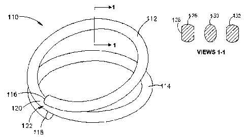
there is seen a surgical clip, generally referenced 110, illustrated in an
open configuration.
Clip 110 is typically wire-like, formed at least partly of a shape memory
alloy, and is of a
coiled configuration so as to include a pair of loops referenced 112 and 114,
having respective
ends referenced 116 and 118. Each of loops 112 and 114 defines a complete
circle from its
end to a point referenced 120 midway along the coil. Thus, coil 110 defines
two complete
circles from end 116 of loop 112 to end 118 of loop 114.
While the various embodiments of clip 110 of the present invention are
illustrated as
defining circular shapes, it will be appreciated by persons skilled in the art
that the present
invention may, alternatively, define any closed geometric shape, such as for
example, an
ellipse. Surgical clips formed having other configurations are used where
surgically
appropriate, in accordance with the organ size, position and other factors.
While the entire clip 110 may be formed of a shape memory alloy, it is
essential that at
least an intermediate portion generally referenced 122 of clip 110 is formed
of a shape
memory alloy displaying SRM behavior. When the clip is mounted on an
applicator device
and cooled to or below a predetermined first temperature, clip 110 transforms
to a plastic
martensitic state. Loops 112 and 114 may be moved apart by the applicator as
seen in Fig. 10.
When heated to or above a second temperature, which is typically below body
temperature,
and while a resistance force is applied by the applicator so as to keep loops
112 and 114 in a
spaced-apart configuration, the stressed shape memory alloy transforms to a
metastable stress-
retained martensitic state. When clip 110 is removed from the applicator and
applied to
adjacent walls of a pair of juxtaposed hollow organ portions (not shown), so
as to cause
anastomosis therebetween, the tissue of the adjacent walls provide a
resistance force to a
19
CA 02575515 2007-01-29
WO 2006/011127 PCT/IL2005/000492
compressive force exerted on loops 112 and 114 by the shape memory alloy of
intermediate
portion 122. Consequently the stressed shape memory alloy transforms from its
stress-
retained martensitic state to its austenitic state. The shape of the clip is
restored thereby
providing for compressive anastomosis.
In order to further control the pressure applied to the tissue walls at the
'point of
contact with clip 110, the cross-section of the wire forming the clip may be
varied, both in
cross-sectional area and in shape. Referring now to cross-sectional views 1-1
in Fig. 10, there
are seen cross-sectional views of alternative profiles taken along line 1-1 of
surgical clip 110.
There is seen a generally circular cross-sectional profile referenced 126,
having planar
surfaces referenced 128 formed therein according to an alternative embodiment
of the present
invention, an elliptical profile referenced 130, and an elliptical-type
profile referenced 132.
In accordance with a preferred embodiment of the invention, suitable surgical
clips
and an applicator device for applying such clips are disclosed in Applicant's
co-pending US
Application No. 10/158,673, entitled "Surgical Clip Applicator Device", filed
May 30, 2002,
which is itself a continuation-in-part application of US Application No.
09/592,518, entitled
"Surgical Clips", filed June 12, 2000. Both applications are incorporated
herein by reference.
Anastomosis ring and crimping support element
With reference to Figs. 11, 12 and 13, in accordance with another embodiment
of the
present invention, there is seen, in Fig. 11 an anastomosis ring generally
referenced 140,
which is configured from a length of shape memory alloy wire 142 as a closed
generally
circular shaped ring, having a central opening referenced 144, a predetermined
wire thickness
and overlapping end portions referenced 146 and 148.
In Fig. 11 there is also seen a cross-sectional view of overlapping end
portions 146 and
148 of anastomosis ring 140 as taken along line 11-11. Each of end portions
146 and 148 has
a flat contact surface referenced 150 formed thereon so as to provide a
similar cross-sectional
profile at overlapping portions 146 and 148 as wire 142.
In order to control the pressure on the tissue walls at the point of contact
with
anastomosis ring 140, the cross-section of the wire forming ring 140 may be
varied, in
accordance with alternative embodiments of the present invention. In Figure 11
there are
further seen cross-sectional views, which are non-limiting examples only, of
alternative
profiles taken along line 12-12 of surgical clip 140. There is seen a
generally circular cross-
CA 02575515 2007-01-29
WO 2006/011127 PCT/IL2005/000492
sectional profile referenced 152. According to an alternative embodiment of
the present
invention, there is seen an elliptical profile referenced 154.
When cooled to or below a first temperature, the shape memory alloy of
anastomosis
ring 140 assumes a stable plastically malleable martensitic state, and an
elastic austenitic
state, when warmed to or above a second, higher temperature. This stable
martensitic state
facilitates that anastomosis ring 140 is expanded and retains an expanded
configuration at the
first, lower temperature. Once ring 140 is warmed to, or above, the second
temperature,
without the imposition of a resisting force, ring 140 returns substantially to
the original
configuration.
However, imposing a resisting force thereto by a resistance means, so as to
resist clip
140 reverting to its original configuration and thereby to cause ring 140 to
exert a
compressive force counter to the resisting force, the shape memory alloy
assumes a
metastable stress-retained martensitic state, so as to apply a predetermined
stressing force to
the resistance means.
Referring now to Figs. 12 and 13, there is seen, respectively, a perspective
and a cross-
sectional view of anastomosis ring generally referenced 140 in crimping
engagement with a
crimping support element referenced generally 160, in accordance with an
embodiment of the
present invention. The cross-sectional view seen in Figure 13 is taken along
line 15-15 in Fig.
12. The Figure also shows intussuscepted adjacent walls 162 of organ portion
163. Crimping
support element 160 includes a short tubular section referenced 164 with an
opening
referenced 165 therethrough, proximal and distal end lugs referenced 166 and
168
respectively. An anastomosis ring 140 is cooled to a reduced temperature,
below body
temperature, where the shape memory alloy transforms from its austenitic to
its martensitic
state. Ring 140 is easily deformed to an insertable size, so as to fit onto a
cooled restraining
means of an anastomosis apparatus (not shown). By warming to or above a second
temperature, anastomosis ring 140 attempts to revert to its original
configuration. As a result
of the warming process while the ring's shape is restrained, the shape memory
alloy is
transformed into its stress-retained martensitic state. When ring 140 is
liberated from a
restraining means (not shown) it applies a predetermined stressing force to
adjacent walls 162
of organ portion 163 and crimping support element 160 as the alloy attempts to
revert to its
austenitic state, thereby causing anastomosis between adjacent walls 162.
21
CA 02575515 2007-01-29
WO 2006/011127 PCT/IL2005/000492
Bone Staples
Clinical experience illustrates that the use of bone staples constructed of a
shape
memory alloy provides definite advantages in the surgical repair of fractured
bones,
particularly of small bones, such in maxilla facial, foot and hand surgery.
SMAs having SIM properties have been proposed for this application. However,
they
have the following problems.
1. If the SMA has a temperature Af above body temperature, the alloy exhibits
SME
behavior (Figs. 3A and 3B) and a device may be implanted in a martensitic
state. Brief
heating will be required to transform the alloy to a metastable martensitic
phase, and on re-
cooling to body temperature, the metastable martensite returns to a stable
martensite state.
However, the alloy does not provide complete shape restoration and the
compression
force is very much reduced. Figure 8, as discussed above, shows the reduced
shape
recovery.
2. If the alloy has an Af temperature below body temperature, the alloy
exhibits SE
(SIM), and the force needed to deform a bone staple is substantially greater
than the
force applied by the staple to a bone fracture when the staple's shape is
restored. This
was discussed in conjunction with Fig. 9 above.
3. When the alloy is in an austenitic state, a special instrument is required
to
deform bone staples and to mechanically conserve the deformed shape. Such an
instrument generally prevents easy installation of the staple.
According to embodiments of the present invention, if an SRM alloy is
utilized, these
disadvantages are substantially overcome. Firstly, SRM utilization provides
almost full shape
restoration in the presence of a permanent compression force referenced 58 in
Fig. 8.
Secondly, the force necessary for shape deformation of a staple in a stable
martensitic
phase is much smaller than when the alloy is in an austenitic state, as
discussed above
in conjunction with Fig. 9.
Referring now to Figs. 14, 15 and 16, in accordance with an embodiment of the
present invention, there are seen respectively the closed, open and inserted
configurations of a bone staple. In Fig. 14, bone staple, referenced 200, is
shown in its
closed configuration. After cooling, the SMA is transformed into a stable
martensitic
state, and the staple is relatively easily deformed to the open configuration
referenced
202 shown in Figure 15. After implantation in a fractured bone 204 as in
Figure 16,
22
CA 02575515 2007-01-29
WO 2006/011127 PCT/IL2005/000492
staples 206, although naturally warmed to body temperature, remain in a
martensitic
state. However, the alloy is no longer in a stable martensite state, but has
been
transformed into a stress-retained martensite state. As the resistance of bone
204
prevents shape restoration, staples 206 attempt to revert to their closed
configuration
200, providing a predetermined stressing force to the fracture site 208 as the
alloy attempts to
revert to its austenitic state.
The physiological process of fracture consolidation takes at least two weeks.
In order
to relieve the compression on the bone fracture site 208 caused by the SRM
state of bone
staples 206, a reconstruction of bone cells takes place at fracture site 208.
There is a
perception that end portion legs referenced 210 of staples 206 are transformed
to a closed
configuration 200 by apparently "cutting" through the bone 204. During the
shape
restoration of staples 206, the transformation of SRM to austenite provides an
almost
constant stress at the fracture site:
Bone Anchor
Referring now to Figs. 17A and 17B, in accordance with an added embodiment of
the
present invention, the mechanism for utilizing a bone anchor generally
referenced 220 is
substantially similar to that required for bone staples, as disclosed herein
above in conjunction
with Figs. 14, 15 and 16. In preparation for locating bone anchor 220, a hole
(not shown) is
drilled into a bone. Bone anchor 220 is pre-cooled so that the shape memory
alloy of anchor
arms referenced 226 is transformed into its stable martensitic state. As
indicated in Fig. 17A,
arms 226 are deformed against a fastener body referenced 228. Thereafter bone
anchor 220 is
positioned in the hole in the bone. Body heat warms fastener 220 to body
temperature,
causing arms 226 to deflect outwards as shown in Fig. 17B against the inner
surface of the
hole, which provides a resisting force thereto. As a result of warming, the
alloy of arms 226 is
transformed into its SRM state. The stress-retained martensite attempts to
transform into
austenite, thereby to cause anchor 220 to be anchored into the bone. Using SRM
allows ease
of deformation without the need for restraining arms 226 in a closed position
but using a
special restraining placement device in some cases may be useful.
Expandable Bone Fastener
Referring now to Figs. 18-20 there are seen, in accordance with an added
embodiment
of the present invention, schematic views of a expandable bone fastener
generally referenced
250 having a generally cylindrical body referenced 252 and at least one pair
of fastening
projections referenced 254 formed from a shape memory alloy. In Figures 18-20,
fastener 250
23
CA 02575515 2007-01-29
WO 2006/011127 PCT/IL2005/000492
is shown as having two pairs of projections 254. While in an austenitic state,
projections 254
remain in an open configuration as indicated in Figures 18 and 19.
The mechanism for utilizing a bone fastener 250 is substantially similar to
that
required for bone staples, as disclosed herein above in conjunction with Figs.
14, 15 and 16.
In order to locate bone fastener 250, a hole with a diameter to facilitate
insertion, is drilled
into the bone (not shown). Prior to insertion, fastener 250 is cooled so as to
cause a
transformation of the shape memory alloy to a fully martensitic state so that
projections 254
are plastically deformable. As indicated in Fig. 20, projections 254 are drawn
together so as to
form a substantially cylindrical configuration generally referenced 256 when
the alloy is in its
martensitic state. Bone fastener 250 is then positioned in the drilled hole in
the bone. Body
heat warms fastener 250 to body temperature, causing projections 254 to
deflect outwards
against the inner surface of the hole, providing a resisting force thereto.
The shape memory
alloy of projections 254 is thereby transformed into an SRM state, as the
stress-retained
martensite attempts to transform into austenite. Projections 254 deflect
outwards causing
fastener 250 to be fastened into the bone.
Using SRM allows ease of deformation without the need for fastening
projections 254
in a closed position and without the need for a special placement device. This
contrasts with
the use of an SIM alloy for a bone anchor, where the anchoring projections
need to be forced
into a closed elastic configuration prior to insertion and have to be inserted
using a special
placement device.
Stents
Carotid angioplasty and stenting are alternatives to surgery for the treatment
of
atherosclerotic carotid arteries, and randomized clinical trials. The
biocompatibility and shape
recoverability of shape memory alloys make them useful for this procedure.
Commonly, superelastic (pseudoelastic) behavior is used for self-expanding
stents.
The self-expanding stent (coil or mesh) diameter is preset to be somewhat
larger than that of
the target vessel. The opened stent is crimped or straightened, leading to a
phase
transformation to stress-induced martensite, restrained in a delivery system
such as a catheter
and then elastically released into the target vessel.
The main difficulties arising from using a SIM alloy stent are restraining the
deformed
stent in its metastable martensitic phase, and preventing it from regaining a
preset shape prior
to final insertion into a restraining means such as a catheter.
24
CA 02575515 2007-01-29
WO 2006/011127 PCT/IL2005/000492
If an SRM element is used, the preparation prior to insertion is easily
accomplished.
Referring now to Fig. 21, in accordance with an embodiment of the present
invention, there is
seen a coil stent generally referenced 230 formed from a shape memory alloy
wire referenced
232 in the shape of a helical coil. Coil stent 230 is cooled to a reduced
temperature, below
body temperature, when the shape memory alloy is transformed from an
austenitic to a
martensitic state. Stent 230 is easily deformed to an insertable size and
shape generally
referenced 234, so as to fit into a cooled delivery applicator or catheter
referenced 236.
Coil 230 retains its insertable size and shape 234 without requiring any
restraining
instruments. It is easily inserted while cool into cooled catheter 236. This
aspect is especially
important when using long stents. The alloy transforms from its stable
martensitic state to its
metastable stress-retained martensitic state, when heated to an ambient
temperature and in the
presence of a restraining catheter. Subsequent insertion into a vessel is
accomplished by
pushing coil stent from catheter 236. Expansion occurs immediately to a preset
size
referenced 238 as stent 230 is released from catheter 236 and the alloy
reverts to its austenitic
state.
Vessel Filter
Referring now to Figs. 22 and 23, there are seen, in accordance with an
additional
embodiment of the present invention, schematic views of a vessel filter
generally referenced
260 prior to and after final installation respectively. After being cooled to
an at least partially
martensitic state, generally about 0 C, filter 260 is deformed so as to be
insertable into a
catheter referenced 262 equipped with a pusher device referenced 264. While in
catheter 262,
filter 260 is warmed. The restrictive force of catheter 262 prevents filter
260 from reverting
to an austenitic state, and correspondingly to its original shape. The stable
martensite of the
alloy undergoes transformation to a stressed retained martensitic (SRM) state.
Catheter 262 is
introduced into a pre-selected blood-vessel referenced 266. By moving pusher
264 forward,
filter 260 is ejected from catheter 262 into blood vessel 266. Upon[o]
unloading, the SRM state
of the alloy of filter 260 transforms to its austenitic state. Primary 263 and
secondary 265
elements expand to their original shape and lodge in blood vessel 266. Primary
263 and
secondary 265 elements form primary and secondary supporting webs referenced
267 and 268
respectively. Any blood clots borne in the blood stream impinge against
supporting webs 267
and 268 and are fragmented thereby.
CA 02575515 2007-01-29
WO 2006/011127 PCT/IL2005/000492
Intrauterine Devices (IUD)
Application of SRM to IUDs is generally similar to that disclosed hereinabove
in
relation to vessel filters as shown in Figs. 22 and 23.
Clamp
In accordance with a further embodiment of the present invention, reference is
now
made to Figs. 24 and 25. Figs. 24 and 25 show schematic perspective views of a
clamp
generally referenced 270 in an open and in a closed configuration,
respectively. Prior to use,
connecting portion referenced 274 is cooled so as to cause the shape memory
alloy from
which clamp 270 is constructed to transform to a plastic martensitic state.
Clamp jaws
referenced 272 are moved apart and retain this deformed shape as indicated in
Fig. 24. After
engaging jaws 272 over a tissue portion or portions (not shown), connecting
portion 274 is
warmed by body heat causing the alloy to begin to revert to an austenitic
state. As the shape
begins to revert to the closed configuration shown in Fig. 25, jaws 272 engage
the selected
tissue therebetween. The presence of the interposed tissue exerts a resisting
force on clamp
270, specifically on connecting por tion 274, preventing complete restoration
of the original
fully closed shape. This allows the martensite of the alloy to be transformed
into stress
retained martensitic (SRM), and, while the SRM transforms to an austenitic
state, clamp 270
exerts a continuing clamping force on the engaged tissue. Alternatively, clamp
270 is
restrained in a suitable applicator prior to use, and the resultant warming
results in SRM
formation.
Dental Implant
Referring now to Figs. 26A and 26B there are seen, in accordance with another
embodiment of the present invention, schematic views of a dental implant
generally
referenced 280. Fig 26A shows the implant prior to implantation while Fig. 26B
shows the
implant after implantation into jawbone 285. Implant 280 includes a body
portion referenced
282 and a plurality of projections referenced 286 formed of a shape memory
alloy. When at
body temperature, that is when dental implant 280 is implanted into jawbone
285, projections
286 are in an austenitic state and are configured to project radially outwards
from body 282 as
in Fig. 26. Prior to implantation (Fig 26A), dental implant 280 is cooled so
as to transform the
alloy of projections 286 to a plastic martensitic state. As shown in Fig. 26A,
projections 286
are folded circumferentially. Prior to implantation, projections 286 are
inserted into a cooled
holding tool referenced 288 so as to retain the projections in a martensitic
state and in their
folded configuration. Dental implant 280 is inserted into a selected jaw-bone
285 cavity in
26
CA 02575515 2007-01-29
WO 2006/011127 PCT/IL2005/000492
Fig. 26B and allowed to warm to body temperature. The alloy begins to revert
to an austenitic
state and folded projections 286 of Fig 26A begin to revert to the extended
projection 286
configuration of Fig. 26B. Projections 286 open outwards and come into
engagement with the
jawbone 285 cavity which applies a resisting force. The alloy transforms into
stress retained
martensitic (SRM) state and applies a continuing force to the bone 285 cavity
so as to remain
permanently engaged therein
Heart Valve Retaining Ring
Jervis, in US 6,306,141, describes the use of a SIM ring to hold a sewing cuff
to a
body of an artificial heart valve. It is claimed that SIM alloys will provide
the best alternative
for this purpose. According to Jervis, the ring is expanded from its initial
austenitic state with
the transformation to SIM. As disclosed hereinabove in relation to Fig. 8, the
stress required
to strain an object in an austenitic state is several times higher than when
the object is in a
martensitic state. Alternatively, the ring is positioned about the valve body,
heated above Af
and then cooled to its original temperature. This procedure causes the ring to
engage the valve
body to the heart.
Using an SRM alloy does not require special heating of the ring. Body heat is
sufficient to cause the requisite phase transformation. Referring now to Fig.
27, in accordance
with another embodiment of the present invention, there is seen a schematic
view of a shape
memory alloy sewing ring 290 having spines (hooks) 294. Ring 290 is covered by
a fabric
seal (cuff) referenced 292, to prevent an infiltration between an artificial
heart valve and a
heart (not shown), utilizing a retaining ring (means) 293. Ring 290 is cooled
to transform the
alloy from which it is constructed from its austenitic to its malleable
martensitic state so that
hooks referenced 294 of sewing ring 290 are distortable to an open
configuration. Thereupon
retaining ring 293 is placed in position over sewing ring 290 and allowed or
caused to warm
to or above the original temperature. The heart valve provides a restraining
means and exerts
a resisting force against closure of ring 290, resulting in the formation of
stress retained
martensite (SRM) in the alloy of ring 290.
It will be appreciated by persons skilled in the art that the present
invention is not
limited by the drawings and description hereinabove presented. Rather, the
invention is
defined solely by the claims that follow.
27