Language selection

Search

Patent 2575577 Summary

Third-party information liability

Some of the information on this Web page has been provided by external sources. The Government of Canada is not responsible for the accuracy, reliability or currency of the information supplied by external sources. Users wishing to rely upon this information should consult directly with the source of the information. Content provided by external sources is not subject to official languages, privacy and accessibility requirements.

Claims and Abstract availability

Any discrepancies in the text and image of the Claims and Abstract are due to differing posting times. Text of the Claims and Abstract are posted:

  • At the time the application is open to public inspection;
  • At the time of issue of the patent (grant).
(12) Patent: (11) CA 2575577
(54) English Title: AIRBAG CUSHION WITH CINCH TUBE FOR REDUCED OUT-OF-POSITION EFFECTS
(54) French Title: COUSSIN GONFLABLE POURVU D'UN TUBE SANGLE POUR REDUIRE LES EFFETS LORSQUE L'OCCUPANT N'EST PAS EN POSITION NORMALE
Status: Granted
Bibliographic Data
(51) International Patent Classification (IPC):
  • B60R 21/16 (2006.01)
  • B60R 21/26 (2011.01)
  • B60R 21/26 (2006.01)
(72) Inventors :
  • WILLIAMS, JEFFREY D. (United States of America)
  • ROSE, LARRY D. (United States of America)
  • SMITH, BRADLEY W. (United States of America)
  • JORDAN, MICHAEL P. (United States of America)
  • JAMISON, PATRICK D. (United States of America)
(73) Owners :
  • AUTOLIV ASP, INC. (United States of America)
(71) Applicants :
  • AUTOLIV ASP, INC. (United States of America)
(74) Agent: MACRAE & CO.
(74) Associate agent:
(45) Issued: 2013-06-18
(86) PCT Filing Date: 2005-08-01
(87) Open to Public Inspection: 2006-04-20
Examination requested: 2010-07-29
Availability of licence: N/A
(25) Language of filing: English

Patent Cooperation Treaty (PCT): Yes
(86) PCT Filing Number: PCT/US2005/027255
(87) International Publication Number: WO2006/041552
(85) National Entry: 2007-01-30

(30) Application Priority Data:
Application No. Country/Territory Date
10/959,256 United States of America 2004-10-06

Abstracts

English Abstract


An airbag cushion is disclosed for use in automotive protective systems. The
airbag cushion includes a tube that may be restricted to prevent gas venting.
A cord is coupled to the tube and to a surface of the cushion. Upon airbag
deployment, the cord extends until taut or extends until the cushion
encounters an obstruction. If pulled taut, the cord tightens the tube and
restricts gas venting. If the cushion encounters an obstruction, the cord
remains lax and the tube is able to vent gas.


French Abstract

L'invention porte sur un coussin gonflable destiné être utilisé dans des systèmes de protection pour automobiles. Ce coussin gonflable comprend un tube pouvant avoir un écoulement limité afin d'empêcher les fuites de gaz. Un cordon est couplé au tube et à une surface du coussin. Lors du déploiement du coussin gonflable, le cordon s'étend jusqu'à ce qu'il soit tendu et que le coussin rencontre un obstacle. S'il est tendu, le cordon resserre le tube et limite les fuites de gaz. Si le coussin rencontre un obstacle, le cordon reste souple et le tube peut libérer le gaz.

Claims

Note: Claims are shown in the official language in which they were submitted.


Claims

1. An airbag cushion module, comprising:
an inflatable airbag cushion defining an interior;
a cinch tube having a base end opposite from a terminal end, wherein the
terminal end has an aperture; and
a cinch cord coupled to the terminal end of the cinch tube and extending
around a majority of the aperture of the terminal end of the cinch tube, the
cinch
cord further coupled to a surface of the airbag cushion such that upon
inflatable
airbag deployment with obstruction, the cinch cord does not fully extend and
the
cinch tube remains open, and upon inflatable airbag deployment without
obstruction,
the cinch cord extends and at least partially closes the aperture at the
terminal end,
wherein the cinch tube is configured such that the aperture at the terminal
end at least partially closes, upon inflatable airbag deployment without
obstruction,
without necessitating closure of the base end of the cinch tube, and
wherein the configuration of the cinch tube and the length of the cinch cord
enables the aperture to at least partially close, upon inflatable airbag
deployment
without obstruction, such that the terminal end is at least partially within
the interior
of the inflatable airbag cushion after the aperture becomes at least partially
closed.

2. The airbag cushion module of claim 1, wherein the cinch tube includes, a
sleeve extending around the majority of the aperture of the terminal end of
the cinch
tube and housing a portion of the cinch cord; and
a sleeve aperture in communication with the sleeve and through which the
cinch cord passes. 10

3. The airbag cushion module of claim 2, further comprising a stopper coupled
to the cinch cord and disposed within the sleeve prior to airbag deployment,
the
stopper adapted to pass through the sleeve aperture upon airbag deployment and

resisting entry into the sleeve aperture after airbag deployment.

4. The airbag cushion module of claim 2, further comprising a tack stitch
inserted into the sleeve and the cinch cord.

5. The airbag cushion module of claim 2, wherein the cinch tube includes a
plurality of loops and wherein the cinch cord is disposed within the loops.

6. The airbag cushion module of claim 1, wherein the surface coupled to the
cinch cord is an internal surface of the inflatable airbag cushion and the
cinch cord
is disposed within the interior of the inflatable airbag cushion.

7. The airbag cushion module of claim 1, wherein the surface coupled to the
cinch cord is an external surface of the inflatable airbag cushion.


11

8. The airbag cushion module of claim 1, further comprising:
a second cinch tube having a base end opposite from a terminal end,
wherein the terminal end has an aperture; and
a second cinch cord coupled to the terminal end of the second cinch tube and
extending around a majority of the aperture of the terminal end of the second
cinch
tube, the second cinch cord further coupled to a surface of the airbag cushion
such
that upon inflatable airbag deployment with obstruction, the second cinch cord
does
not fully extend and the second cinch tube remains open, and
upon inflatable airbag deployment without obstruction, the second cinch cord
extends and at least partially closes the aperture at the terminal end without

necessitating closure of the base end of the second cinch tube;
wherein the second cinch tube is configured such that the aperture at the
terminal end of the second cinch tube at least partially closes, upon
inflatable airbag
deployment without obstruction, without necessitating closure of the base end
of the
second cinch tube, and
wherein the configuration of the second cinch tube and the length of the
second cinch cord enables the aperture to at least partially close, upon
inflatable
airbag deployment without obstruction, such that the terminal end of the
second
cinch tube is at least partially within the interior of the inflatable airbag
cushion after
the aperture of the second cinch tube becomes at least partially closed.

9. The airbag cushion module of claim 8, wherein the cinch tubes are
symmetrically disposed on the airbag cushion.


12

10. The airbag cushion module of claim 1, further comprising a vent disposed
on
the airbag cushion and adapted to vent gas during airbag deployment with and
without obstruction.

11. An airbag cushion module, comprising:
an inflatable airbag cushion defining an interior;
a first cinch tube and a second cinch tube, wherein each cinch tube has a
base end opposite from a terminal end, and each terminal end has an aperture;
and
a cinch cord coupled to the first and second cinch tubes and extending
around a majority of the aperture of the terminal end of each of the cinch
tubes;
wherein the cinch cord passes through a cinch loop coupled to a surface of
the airbag cushion at a location such that upon inflatable airbag deployment
with
obstruction, the cinch cord does not fully extend and the cinch tubes remain
open,
and
upon inflatable airbag deployment without obstruction, the cinch cord extends
and at least partially closes the apertures of the terminal ends of the cinch
tubes;
wherein the cinch tubes are configured such that the apertures at the terminal

ends at least partially closes, upon inflatable airbag deployment without
obstruction,
without necessitating closure of the base ends of the cinch tubes, and
wherein the configuration of the cinch tubes and the length of the cinch cord
enables the apertures to at least partially close, upon inflatable airbag
deployment
without obstruction, such that the terminal ends are at least partially within
the
interior of the inflatable airbag cushion after the apertures becomes at least
partially
closed.

13

12. The airbag cushion module of claim 11, wherein the first and second cinch
tubes each include,
a sleeve extending around the majority of the aperture of the terminal end of
the cinch tube and housing a portion of the cinch cord; and
a sleeve aperture in communication with the sleeve and through which the
cinch cord passes.

13. The airbag cushion module of claim 12, further comprising a first stopper
coupled to the cinch cord and disposed within the sleeve of the first cinch
tube and a
second stopper coupled to the cinch cord and disposed within the sleeve of the

second cinch tube, the first and second stoppers adapted to pass through
corresponding sleeve apertures upon airbag deployment and resisting entry into
the
sleeve apertures after airbag deployment.

14. The airbag cushion module of claim 12, further comprising tack stitches
inserted into the sleeves of the first and second cinch tubes and the cinch
cord.

15. The airbag cushion module of claim 11, wherein the first and second cinch
tubes each include a plurality of loops and wherein the cinch cord is disposed
within
the loops.

16. The airbag cushion module of claim 11, wherein the surface coupled to the
cinch loop is an interior surface of the inflatable airbag cushion and the
cinch cord is
disposed within the interior of the inflatable airbag cushion.

14

17. The airbag cushion module of claim 11, wherein the surface coupled to the
cinch cord is an external surface of the inflatable airbag cushion.

18. The airbag cushion module of claim 11, wherein the first and second cinch
tubes are symmetrically disposed on the inflatable airbag cushion.

19. The airbag cushion module of claim 11, further comprising a vent disposed
on the inflatable airbag cushion and adapted to vent gas during airbag
deployment
with and without obstruction.

20. An airbag cushion module, comprising:
an inflatable airbag cushion defining an interior;
means for venting gas out of the airbag; and
means for restricting gas venting by cinching the venting means to reduce the
circumference of the venting means at a terminal end without necessitating
closure
of an opposing base end upon inflatable airbag deployment without obstruction
and
enabling the venting means to remain open upon inflatable airbag deployment
with
obstruction,
wherein the configuration of the venting means and configuration of the
means for restricting gas venting enable the venting means to at least
partially
close, upon inflatable airbag deployment without obstruction, such that the
terminal
end is at least partially within the interior of the inflatable airbag cushion
after the
venting means becomes at least partially closed.


15

Description

Note: Descriptions are shown in the official language in which they were submitted.


CA 02575577 2010-07-29

AIRBAG CUSHION WITH CINCH TUBE FOR REDUCED
OUT-OF-POSITION EFFECTS
Technical Field
[0001] The present invention relates generally to the field of automotive
protective
systems. More specifically, the present invention relates to inflatable
airbags for
automobiles.

Brief Description of the Drawings
[0002] Understanding that drawings depict only typical embodiments of the
invention and are not therefore to be considered to be limiting of its scope,
the
invention will be described and explained with additional specificity and
detail
through the use of the accompanying drawings in which:
[0003] FIG. 1A is a cross-sectional view of an embodiment of a deploying
airbag
cushion.
[0004] FIG. 1B is a cross-sectional view of the deploying airbag cushion of
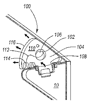
FIG.
1A.
[0005] FIG. 1C is a cross-sectional view of an embodiment of a deploying
airbag
cushion of FIGS 1A and 1B.
[0006] FIG. 2A is a perspective view of an embodiment of a cinch tube.
[0007] FIG. 2B is a perspective view of the cinch tube of FIG. 2A.
[0008] FIG. 3 is a perspective view of another embodiment of a cinch tube.
[0009] FIG. 4 is a perspective view of an additional embodiment of a cinch
tube.
[0010] FIG. 5A is a cross-sectional view illustrating initial deployment of an
airbag
cushion.
1

CA 02575577 2010-07-29


[0011] FIG. 5B is a cross-sectional view illustrating a deploying airbag
cushion.
[0012] FIG. 5C is a cross-sectional view of a deployed airbag cushion.
[0013] FIG. 5D is a cross-sectional view illustrating initial deployment of
an airbag
cushion.
[0014] FIG. 5E is a cross-sectional view illustrating a deploying airbag
cushion.
[0015] FIG. 5F is a cross-sectional view of a deployed airbag cushion.
[0016] FIG. 6 is a diagram illustrating an airbag cushion venting graph in
relation
to an airbag cushion's deployment.
[0017] FIG. 7 is a cross-sectional view of an alternative embodiment of a
deployed airbag cushion.
[0017.1] FIG. 8 is a side view of one embodiment of a cinch tube.
[0017.2] FIG. 9 is a side view of another embodiment of a cinch tube.
Detailed Description of Preferred Embodiments
[0018] Described below are embodiments of an airbag cushion and venting
mechanism. As those of skill in the art will appreciate, the principles of the
invention
may be applied to and used with a variety of airbag deployment systems
including
frontal driver and passenger airbags, knee airbags, overhead airbags, curtain
_
airbags, and the like. Thus, the present invention is applicable to airbag
cushions of
various shapes and sizes.
[0019] Airbag cushions are frequently located in an instrument panel and
directly
in front of an occupant. During a collision, the airbag cushion inflates and
deploys
through a cosmetic cover. The airbag cushion deploy g towards the occupant and

provides a restraint. A dangerous situation occurs where an occupant is
positioned
to closely to the airbag which causes the occupant to contact the airbag as it
is

2

CA 02575577 2010-07-29


deploying. Ideally, the occupant should be in position to contact the airbag
only after
full deployment. It would be advantageous to provide an airbag with a softer
deployment when an occupant is out-of-position. Embodiments described below


2a

WO 2006/041552 CA 02575577 2007-01-30 PCT/US2005/027255
provide an airbag cushion that responds to an occupant's position and vents
accordingly to avoid excessive deploying impact.
[0020] Embodiments disclosed herein include a cinch cord that is connected at
one end to a cinch tube and at an opposing end to an interior surface of the
cushion.
If an occupant is in close proximity to the deploying airbag and restricts
normal
inflation, the cinch tube remains open and allows gas to rapidly escape. If
the
occupant is in a normal position and inflation is unrestricted, the tension
pulls on the
cinch tube to quickly close the cinch tube. Closure retains gas for normal
occupant
restraint. Thus, the cinch tube may be used as a variable feature in out-of-
position
conditions and in normal restraint conditions. In this manner, the airbag
cushion is
sensitive to obstructive expansion of the cushion.
[0021] With reference now to the accompanying figures, particular embodiments
of the invention will now be described in greater detail. FIGS. 1A through 10
depicts
a cross-sectional view of an airbag cushion 100 deploying from a housing 10.
The
airbag cushion 100 includes a cinch tube 102 that may include a nylon woven
fabric-
type or other suitable material known in the art. The cinch tube 102 may be
embodied with a generally cylindrical shape and having opposing open ends to
enable gas venting. The cinch tube 102 may have any suitable shape such as
rectangular, triangular, or polygon shapes. The cinch tube 102 may be embodied

with a height that is sufficient to achieve desired closure.
[0022] The cinch tube 102 is coupled to a surface 104 of the airbag cushion
100
and circumvents an aperture 106 in the surface 104. The surface 104 may form
part
of an airbag cushion throat 108 or may be proximate to the throat 108. The
cinch
tube 102 may extend into the airbag cushion interior 110 or may extend from
the
airbag cushion 100. For illustrative purposes, a single cinch tube 102 is
disclosed
3

WO 2006/041552 CA 02575577 2007-01-30 PCT/US2005/027255
but the airbag cushion 100 may include multiple cinch tubes to provide
required
venting capability.
[0023] The airbag cushion 100 includes a cinch cord 112 that couples or
engages the cinch tube 102 and couples to a surface 114 of the airbag cushion
100.
The cinch cord 112 may include a nylon material or other suitable material
known in
the art. The surface 114 may be an interior surface of the airbag cushion as
depicted. The surface 114 may be the surface opposing the face surface 116 of
the
airbag cushion that contacts the occupant. Alternatively, the surface 114 may
be
disposed proximate to a surface opposing the face surface 116. The surface 114

may be an exterior surface such as the face surface 116. Thus, the cinch cord
112
may extend through the interior 110 of the airbag cushion 100 or may be
positioned
exterior to the airbag cushion 100. The location of the surface 114 depends on

module deployment angle, vehicle interior geometry, and cushion fold type.
[0024] In FIG. 1A, the initially deploying airbag cushion 100 has a slack
cinch
cord 112 and:the cinch tube 102 remains open. In FIG. 1B, the cinch cord 112
is
pulled taut and the cinch tube 102 begins to close. In FIG. 1C, the cinch cord
112 is
completely taut and the cinch tube 102 is closed.
[0025] Referring to FIGS. 2A and 2B, perspective views of one embodiment of a

cinch tube 102 in both the open and closed positions are shown. The cinch cord
112
circumvents a majority of the perimeter 200 of the cinch tube 102 in order to
properly
tighten and restrict the cinch tube 102. The cinch cord 112 has a length that
includes an initial free length and a circumference of the ,cinch tube 102.
The cinch
cord 112 may be disposed within a sleeve 202 that is formed within the cinch
tube
102. Access to the sleeve 202 is through a sleeve aperture 204 formed in the
cinch
tube 102. The cinch cord 112 enters the sleeve aperture 204, feeds through the
4

WO 2006/041552 CA 02575577 2007-01-30PCT/US2005/027255
sleeve 202, and is coupled at an end 206 within the sleeve 120 to the cinch
tube
102. Coupling may be achieved by stitches, bonds, or adhesives.
[0026] Referring to FIG. 3, an alternative embodiment of a cinch tube 300 is
shown wherein a cinch cord 302 loops around the majority of the cinch tube
perimeter 304. The cinch tube 300 includes first and second sleeve apertures
306,
308 that are in communication with a sleeve 310 formed within the cinch tube
300.
The cinch cord 302 enters the first sleeve aperture 306, extends along the
sleeve
310, and exits out the second sleeve aperture 308.
[0027] Referring to FIG. 4, an alternative embodiment of a cinch tube 400 is
shown wherein the cinch tube 400 includes a plurality of cinch loops 402. The
cinch
loops 402 may be disposed on a periphery 404 as shown or on an inner or outer
surface 406, 408 of the cinch tube 400. A cinch cord 410 is fed through the
cinch
loops 402 and is thereby able to restrict the cinch tube 400 as needed.
[0028] Figures 5A-C illustrate three stages of a deploying airbag cushion 500
without obstruction in the deploying path. The depicted airbag cushion 500
includes
two cinch tubes 502 symmetrically disposed on the cushion 500 and two vents
504
symmetrically disposed on the cushion 500. The vents 504 provide consistent
venting of the airbag cushion 500 and are not restricted by an occupant's
position.
The vents 504 may be optional in certain cushion embodiments based on venting
requirements. The locations for the cinch tubes 502 and vents 504 may vary as
does the number of tubes 502 and vents 504. An occupant 12 is in a normal
seating
position which will allow the airbag cushion 500 to fully expand before
impacting the
occupant. In this manner, the occupant 12 benefits from the full restraint
capability
of the airbag cushion 500.
5

, WO 2006/041552
CA 02575577 2007-01-30
PCT/US2005/027255
[0029] In FIG. 5A, the initial breakout of the airbag cushion
500 occurs. The
cinch tubes 502 are open and, in the depicted embodiment, extend from the
airbag
cushion 500. In FIG. 5B, cinch cords 506 corresponding to each cinch tube 502
are
pulled taut and the cinch tubes 502 are restricted. The cinch tubes 502 may
also be
pulled within the interior 508 of the airbag cushion 500. In FIG. 50, the
cinch tubes
502 are completely closed, the gas vents through the vents 504, and normal
restraint
is provided to the occupant 12.
[0030] Figures 5D-F illustrate three stages of a deploying
airbag cushion 500 with
obstruction in the deploying path. An occupant 12 is out-of-position and
obstructs
the deploying airbag cushion 500 and prevents the airbag cushion 500 from
fully
inflating. In FIG. 5D, the airbag cushion 500 begins initial deployment as in
FIG. 5A.
In FIG. 5E, the airbag cushion 500 impacts the occupant 12 and the cinch cords
506
remain slack. The cinch tubes 502 remain open and venting rapidly occurs from
tubes 502 and vents 504. The cushion inflation is restricted but the occupant
12
receives less than the full deployment loading of the cushion 500. In FIG. 5F,
the
.
cushion 500 is partially inflated and provides limited restraint. Venting
continues
through the tubes 502 and vents 504.
[0031] Referring to FIG. 6, a graph illustrating cinch tube
venting as a function of
airbag cushion displacement is shown. For reference, an airbag cushion 600 is
shown in various stages of deployment. The airbag cushion 600 includes two
symmetrically disposed cinch tubes 602. During initial deployment, the airbag
cushion 600 is unfolding and the cinch tubes 602 provide little or no venting.
The
airbag cushion 600 expands into an out-of-position zone 604 where, if
obstructed,
the cinch tubes 602 will remain completely or nearly open and full venting
occurs. In
this zone an occupant does not receive the full restraint capability but does
benefit 6

WO 2006/041552 CA 02575577 2007-01-30 PCT/US2005/027255

from limited restraint. If unobstructed, the airbag cushion 600 expands into a
gray
zone 606 where partial closure of the cinch tubes 602 begins and venting is
limited.
The cinch tubes 602 may be pulled into the airbag cushion 600 depending on the

cushion design. If further unobstructed, the airbag cushion 600 fully expands
to the
restraint zone 608. At this zone, the cinch tubes 602 completely close and an
occupant benefits from the full restraint capability of the airbag cushion
600.
[0032] Referring to FIG. 7, an alternative embodiment of an airbag cushion 700
is
shown. The airbag cushion 700 includes two symmetrical cinch tubes 702 that
may
be embodied as described above. The cinch tubes 702 have been pulled
completely
into the airbag cushion interior 704. Rather than having cinch cords
corresponding
to each cinch tube 702, a single cinch cord 706 is used. The cinch cord 706 is

coupled to or engages each cinch tube 702 in a manner similar to that
previously
described. The cinch cord 706 passes through a cord loop 708 that is coupled
to an
interior surface 710. The cord loop 708 may be formed of a fabric material
similar or
identical to that of the airbag cushion 700. The cinch cord 706 may freely
pass
through the loop 708 and may therefore be referred to as a "floating" cinch
cord. In
an alternative embodiment, the cinch cord 706 may be disposed on the airbag
cushion exterior and passes through a cord loop 708 coupled to an exterior
surface
of the airbag cushion 700. In either embodiment, airbag cushion deployment
pulls
the cinch cord 706 taut and closes both cinch tubes 702.
[0033] Referring to FIG. 8, an alternative embodiment of a cinch cord 800
disposed within a cinch tube 802 is shown. The cinch tube 802 includes a
sleeve
804 that extends around a periphery of the cinch tube 802 and houses a portion
of
the cinch cord 800. The cinch cord 800 exits from the sleeve 804 through a
sleeve
aperture 806. The cinch cord 800 includes a stopper 808 that, prior to airbag
7

WO 2006/041552 CA 02575577 2007-01-30 PCT/US2005/027255
cushion deployment, is disposed within the sleeve 804. The stopper 808 is
sized
and configured to permit deploying movement, i.e. from the sleeve 804 and
through
the aperture 806, but does restricts movement through the aperture 806. In
operation, the stopper 808 prevents a cinch tube 802 from reopening after
deployment and closure of the cinch tube 802. This may occur during deflation
of an
airbag cushion as the cinch cord becomes slack. Venting is thereby directed to
other
vents.
[0034] Referring to FIG. 9, an alternative embodiment of a cinch tube 900 is

shown with a cinch cord 902 partially disposed within. The cinch tube 900
includes a
sleeve 904 that contains a portion of the cinch cord 902. The cinch tube 900
further
includes tack stitching 906 that is inserted through the sleeve 904 and the
cinch cord
902 to retain the cinch cord 902 and prevent inadvertent closing of the cinch
tube
900 during shipping and handling. The tack stitching 906 is designed to be
easily
broken and provides no interference to airbag cushion deployment.
[0035] Embodiments disclosed herein illustrate novel techniques for venting
an
airbag cushion to retain an open vent when an occupant obstructs the path of a

deploying cushion and closed when an occupant does not obstruct a deploying
cushion. Airbag cushions provide improved safety by deploying with less
pressure
when an occupant is obstructing deployment. The airbag cushions deploy with
more
pressure when an occupant is not obstructing deployment and when high pressure
is
required to provide the necessary restraint. The airbag cushions described
herein
have application to both driver and passenger positions. Furthermore, the
airbag
cushions may be configured in a variety of sizes based on design constraints.
[0036] Various embodiments for cinch tubes have been disclosed herein. Cinch
tubes 102, 300, 400, 502, 602, 702, 802, and 900 are examples of means for
venting
8

WO 2006/041552 CA 02575577 2007-01-30 PCT/US2005/027255
gas out of the airbag and circumventing an aperture disposed in the airbag.
Cinch
cords 112, 302, 410, 506, 706, 800, and 902 are examples of means for
restricting
gas venting by cinching the venting means to reduce the circumference of the
venting means upon inflatable airbag deployment without obstruction and
enabling
the venting means to remain open upon inflatable airbag deployment with
obstruction.
[0037] It will be apparent to those having skill in the art that changes may
be
made to the details of the above-described embodiments without departing from
the
underlying principles of the invention. Embodiments of the invention in which
an
exclusive property or privilege is claimed are defined as follows.


9

Representative Drawing
A single figure which represents the drawing illustrating the invention.
Administrative Status

For a clearer understanding of the status of the application/patent presented on this page, the site Disclaimer , as well as the definitions for Patent , Administrative Status , Maintenance Fee  and Payment History  should be consulted.

Administrative Status

Title Date
Forecasted Issue Date 2013-06-18
(86) PCT Filing Date 2005-08-01
(87) PCT Publication Date 2006-04-20
(85) National Entry 2007-01-30
Examination Requested 2010-07-29
(45) Issued 2013-06-18

Abandonment History

There is no abandonment history.

Maintenance Fee

Last Payment of $473.65 was received on 2023-07-04


 Upcoming maintenance fee amounts

Description Date Amount
Next Payment if small entity fee 2024-08-01 $253.00
Next Payment if standard fee 2024-08-01 $624.00

Note : If the full payment has not been received on or before the date indicated, a further fee may be required which may be one of the following

  • the reinstatement fee;
  • the late payment fee; or
  • additional fee to reverse deemed expiry.

Patent fees are adjusted on the 1st of January every year. The amounts above are the current amounts if received by December 31 of the current year.
Please refer to the CIPO Patent Fees web page to see all current fee amounts.

Payment History

Fee Type Anniversary Year Due Date Amount Paid Paid Date
Registration of a document - section 124 $100.00 2007-01-30
Application Fee $400.00 2007-01-30
Maintenance Fee - Application - New Act 2 2007-08-01 $100.00 2007-08-01
Maintenance Fee - Application - New Act 3 2008-08-01 $100.00 2008-07-31
Maintenance Fee - Application - New Act 4 2009-08-03 $100.00 2009-06-17
Maintenance Fee - Application - New Act 5 2010-08-02 $200.00 2010-07-13
Request for Examination $800.00 2010-07-29
Maintenance Fee - Application - New Act 6 2011-08-01 $200.00 2011-07-28
Maintenance Fee - Application - New Act 7 2012-08-01 $200.00 2012-07-13
Final Fee $300.00 2013-04-04
Maintenance Fee - Patent - New Act 8 2013-08-01 $200.00 2013-06-13
Maintenance Fee - Patent - New Act 9 2014-08-01 $200.00 2014-08-01
Maintenance Fee - Patent - New Act 10 2015-08-03 $250.00 2015-07-20
Maintenance Fee - Patent - New Act 11 2016-08-01 $250.00 2016-07-18
Maintenance Fee - Patent - New Act 12 2017-08-01 $250.00 2017-07-24
Maintenance Fee - Patent - New Act 13 2018-08-01 $250.00 2018-07-19
Maintenance Fee - Patent - New Act 14 2019-08-01 $250.00 2019-07-03
Maintenance Fee - Patent - New Act 15 2020-08-03 $450.00 2020-07-01
Maintenance Fee - Patent - New Act 16 2021-08-02 $459.00 2021-07-27
Maintenance Fee - Patent - New Act 17 2022-08-01 $458.08 2022-07-25
Maintenance Fee - Patent - New Act 18 2023-08-01 $473.65 2023-07-04
Owners on Record

Note: Records showing the ownership history in alphabetical order.

Current Owners on Record
AUTOLIV ASP, INC.
Past Owners on Record
JAMISON, PATRICK D.
JORDAN, MICHAEL P.
ROSE, LARRY D.
SMITH, BRADLEY W.
WILLIAMS, JEFFREY D.
Past Owners that do not appear in the "Owners on Record" listing will appear in other documentation within the application.
Documents

To view selected files, please enter reCAPTCHA code :


To view images, click a link in the Document Description column. To download the documents, select one or more checkboxes in the first column and then click the "Download Selected in PDF format (Zip Archive)" or the "Download Selected as Single PDF" button.

List of published and non-published patent-specific documents on the CPD .

If you have any difficulty accessing content, you can call the Client Service Centre at 1-866-997-1936 or send them an e-mail at CIPO Client Service Centre.


Document
Description 
Date
(yyyy-mm-dd) 
Number of pages   Size of Image (KB) 
Cover Page 2007-04-17 1 39
Abstract 2007-01-30 1 65
Claims 2007-01-30 5 141
Drawings 2007-01-30 7 107
Description 2007-01-30 9 381
Representative Drawing 2007-01-30 1 7
Description 2010-07-29 10 387
Claims 2012-12-18 6 196
Representative Drawing 2013-05-29 1 9
Cover Page 2013-05-29 1 40
Fees 2011-07-28 1 21
Assignment 2007-01-30 9 311
Fees 2008-07-31 1 23
Fees 2009-06-17 1 22
Prosecution-Amendment 2010-07-29 5 134
Prosecution-Amendment 2010-07-29 1 30
Fees 2010-07-13 1 22
Prosecution-Amendment 2012-12-18 9 320
Prosecution-Amendment 2012-06-19 2 61
Fees 2012-07-13 1 23
Correspondence 2013-04-04 1 30
Fees 2013-06-13 1 22
Fees 2014-08-01 1 24