Note: Descriptions are shown in the official language in which they were submitted.
CA 02575609 2007-01-30
WO 2005/013221 PCT/CA2004/001428
AN ACCESS ANNUNCIATOR
Cross Reference to Related Applications
This application claims the benefit of priority under 35 U.S.C. 119(e) to U.
S.
Provisional Application serial No. 60/490,957, filed on July 30, 2003 the
entirety of
which is incorporated herein by reference.
Field of the Invention
This invention relates to an alarm, or more simply, to an "alert" system, for
notifying a
user of unauthorized entry into a place or location. In particular, a siinpler
form of an
alarm system is provided.
Baclcjzround of the Invention
Conventional alarm systems are well known in the art. Commonly, known burglar
alarm systems commence their fi.inctional cycle as the occupant prepares to
leave the
protected area. The system displays the security status of each zoning area
and if
verified satisfactory, the system will then allow itself to be armed by means
of an
activating switch or equivalent, on its' control center, which sequentially
energizes a
timed delay for allowing the occupants to leave the protected area within a
given short
period of time. On leaving the protected area, the entrance/exit door is
locked. The
timed delay device then relinquishes control to the monitoring devices of the
control
center. The system's control center is now poised to energize several
different remote
devices, the number of which is dependent upon the quality and sophistication
of the
alarin system. If there is no violation, between departure and arrival of the
occupants,
its' alarin devices will remain deactivated. Provided the system is disarmed
immediately on entering said protected zone, by entering a secret code, or any
other
form of security, the system is disarm. If however there is illegal access,
the system
goes into automatic defense mode by activating one or several alarm signaling
devices. This can include, for example, notifying the appropriate
organizations, and/or
persons of the illegal entry, as well as activating audible, visual or other
types of
-1-
CA 02575609 2007-01-30
WO 2005/013221 PCT/CA2004/001428
alarms which may be installed.
These devices however, comprise several additional different features than the
devices
of the present invention. As such, they are much larger devices which require
surface
mounting in conspicuous locations. This gives rise to the teiuptation of
tampering and
manipulative exploitation of the keypad coding system within its' control
center.
Accordingly, while they have proven to be effective for their intended use, it
would be
desirable to provide an alerting device which would alert the user of
unauthorized
entry into a specific location. Also, it would be advantageous to provide a
simple
system for alerting a user of illegal entry by using a device which is
inconspicuous in
normal usage.
Summary of the Invention
It is a principal advantage of the present invention to provide an alert
system which is
simpler in operation that currently lcnown devices. It is again to be
emphasized that
the present invention does not serve to replace, or improve on the
conventional alarm
systems; and that it merely fills the need for a more simple, and less
expensive means
of illegal entry recordal or notification.
As such, the advantages set out hereinabove, as well as other objects and
goals
inherent thereto, are at least partially or fully provided by the access
annunciator of the
present invention, as set out herein below.
Accordingly, in one aspect, the present invention provides a device for
informing on
entry gained within any enclosure having an access opening, which device
comprises
a pulsed switching means, and an alert signaling means for generating an alert
signal
when activated by said pulsed switching means.
The pulsed switching means is merely any switch or device which can provided
an
onloff signal when engaged or contacted.
-2-
CA 02575609 2007-01-30
WO 2005/013221 PCT/CA2004/001428
Accordingly, the present invention comprises principal components that, wllen
installed, will function as a sealed tamper proof annunciating device, small
enough for
inconspicuous insertions, or surface mounting.
Further, the device provides the features of a substantial switching means,
which will
essentially energizing an alert device on its' sequential third attempt.
Thereby said
alert device remains in an energized state on all subsequent attempts, and
does not
change status until manually reset. This represents one complete functional
cycle of
said invention.
As such, in a further aspect, the present invention also provides a device as
hereinabove described, wherein said device coinprises a counter memory means
for
causing it to operationally count a specific number of events, having alert
signaling
means, and reset means.
For example, the access annunciator is preferably configured so as to trigger
an alert
the third time the system is activated. In a typical use, on system reset, the
door within
its' access opening will be closed or locked by authorized person prior to
leaving the
area for which intrusive information is required. On return of the user, being
a second
authorized entry, the status of the alert signal is inspected. If the access
annunciator
has not, or does not activate, this is a clear indication that no one else had
opened said
door. If however, said authorized person observes by inspection that said
alert system
is energized, for example by a flashing LED, or other designed alert signaling
means,
having a timed delay lasting some minutes on each event of opening said door,
then
this is a sure indication that the door was opened at least three times,
inclusive of the
previous, and present events. As such, the user is notified of entry by some
other
person.
Said alert component is preferably controlled by a timed delay component,which
initializes on each event of opening said door, and energizes said alert
component for
a specified duration to conserve battery energy. This condition will persist
until
-3-
CA 02575609 2007-01-30
WO 2005/013221 PCT/CA2004/001428
disarmed by an authorized individual. The Access Annunciator will be again
initialized by its' reset means. This will connnonly constitutes one complete
functional
cycle of said invention.
The present invention also provides, an access annunciator device comprising
an
access switch which provides an access signal when said access switch is
activated, an
activation counter which counts the number of access signals received, an
alert system
wliich determines that a pre-set number of access signals have been received
and
activates an alert signaling means to generate an alert signal.
Brief Description of the Drawings
Embodiments of this invention will now be described by way of example only in
association with the accoinpanying drawings in wlzich: .
Figure 1 illustrates a side view of one type of access Annunciator of the
present
invention;
Figure 2 provides a side view of a similar type of access Annunciator;
Figure 3 provides a perspective view of a bracket for of a component of the
access
Annunciator;
Figure 4 provides a perspective view of a "principal" body which has input and
output conductors positioned for top, side, or end entry;
Figure 5 provides a side view of another aforementioned momentary switching
means;
Figure 6 provides a perspective view of another "principal" unit similar to
that shown
in Figure 4;
-4-
CA 02575609 2007-01-30
WO 2005/013221 PCT/CA2004/001428
Figure 7 shows a perspective view of a second mounting bracket;
Figure 8 is a block diagram of the motion sensor alarm system, in accordance
with
the prior art;
Figure 9 is a block diagram of a second type of prior art alarm systems;
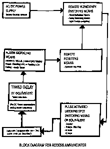
Figure 10 is a block diagram of one embodiment of the device of the present
invention;
Figure 11 is a perspective view of an optional hand held portable Device
Reader;
Figure 12 is a perspective view of a hinge conductor for use in the practise
of the
present invention;
Figure 13 is a perspective view of a hinge switch similar to the conductor of
Figure
12 being used in combination with a principal unit;
Figure 14 is a block diagram of a hand held portable Device Reader;
Figure 15 is a block diagram of a Wireless Controller for use with the
principal unit;
and
Figure 16 is a block diagram of an optional, wireless Access Annunciator.
Detailed Description of the Preferred Embodiments
The novel features which are believed to be characteristic of the present
invention, as
to its structure, organization, use and method of operation, together with
further
objectives and advantages thereof, will be better understood from the
following
drawings in which a presently preferred embodiment of the invention will now
be
illustrated by way of example only. In the drawings, like reference numerals
depict
-5-
CA 02575609 2007-01-30
WO 2005/013221 PCT/CA2004/001428
like elements.
It is expressly understood, however, that the drawings are for the purpose of
illustration and description only and are not intended as a definition of the
limits of
the invention.
In Figure 1, one type of an "insertion" Annunciator (1) is shown, comprising a
momentaly switching means (15), as well as various components and necessary
semiconductors as may be found necessary, all of which are housed within or
connected to, the same principal unit (10), and which are adapted to be
installed
within, for example, a door, or its' adjacent access opening. The device has
an alert
signaling component (in this case an LED (20)), and resetting switch (25)
which is
remotely located to that of principal unit (10). Inside of principal unit (10)
is a battery
for proper functioning of the unit, and an optional low battery LED indicator
(19) is
provided.
It is clear that an access annunciator device (1) according to the present
invention is
ideal for monitoring access doors, windows, filing cabinets, desk draws,
closets,
briefcases, suitcases, and the like, wherein it is desirable to monitor access
to or from
an enclosure or specific area.
In Figure 2 a similar insertion type Annunciator (1A) is shown which comprises
a
second type of said momentary switching means (16), inclusive of the
coinponents,
and necessary semicoriductors as may be found necessary, which are housed with
principal unit (10).Again this unit (10) may be installed within either door
(11), or its'
adjacent access opening (12), having alert signaling component (20), a low
battery
indicator (19), and resetting switch (25), remotely located to that of their
principal unit
(10).
The principal unit (10) can be inserted into a hole within a door, or a door
frame, or
example, or might be attached to a nearby surface using, for example a bracket
(30),
-6-
CA 02575609 2007-01-30
WO 2005/013221 PCT/CA2004/001428
as shown in Figure 3.
In Figure 4, a different shape of principal unit (l0A) is shown which is
located
remotely of the switching means. Again, however, the principal unit has input
and
output conductors positioned on its top, end and side panels.
In Figure 5, a momentary switching means (17) is shown which is located
remotely to
that of principal unit (l0A). Switching means (17) is connected to principal
unit (l0A)
using a suitable corniection means, including, for example, wires, or by
wireless
communication methods. Again switching means (17) is adapted to be located
remote
of its' principal unit (l0A), and can be inserted into a door or door frame,
as shown, or
might be surface mounted on door (11) or its' adjacent access opening (12).
Figure 6 shows a further principal unit (l0A) having its principal components
(inclusive of alert signal (20), and resetting means (25)) etc., housed within
container
(l0A), and having a momentary switching means (17) remotely located to that of
principal unit (1 OA).
Figure 7 shows a retaining bracket (30A) having a different cross sectional
coiifiguration for surface mounting said principal unit (10A) to a desired
surface.
F'igure 8 is a block diagram of the motion sensor alarm system, according to
the prior
art. Its operation can be described as follows:
Personal Portable Alarm - Motion Sensor Type
The alarin system shown in Fig. 8 is a prior art personal, portable intrusion
Alarm
device, whose primary function is accomplished by means of Motion Sensor,
comprising a DC power supply, having a single pole single throw activation
switch, a
motion sensor, and an audible alarm, all housed in one container, and having a
hanging strap, whereby the system is hung around the door lcnob/handle located
on the
-7-
CA 02575609 2007-01-30
WO 2005/013221 PCT/CA2004/001428
internal surface of the door within the protected area. The door is locked
from the
inside, and the alarm is activated by activating the switch. The system is now
in a
monitoring mode whereby it is poised to detect any movement caused by turning
the
door handle from the outside, as well as movement of the door as sensed by the
alarm
systein, at which time its' alarm signal will be energized (usually an audible
alarm),
and whose alarin inode is also deactivated by turning off said switch. If
there is no
intrusion, the system may also be disarmed by deactivating the on/off switch.
This
system is small, light weight, and ideal for travelers staying overnight in
hotels or at
guest houses. It allows free movement within the protected area by its'
occupants
when armed. However, it is prone to false alarms by other guests inadvertently
rotating the door handle on the outside of its' protected area. Due to its'
close
proximity to the intended intruders' hand, it can also be easily, and quickly
disarmed
by an intruder if the intruder gains instant access by using a key.
Figure 9 is a block diagram of still another type of prior art alarm system,
namely that
of the passive Infrared variety. Its operation can be described as follows:
Personal Portable Alarm - Passive Infrared Sensor Type
The prior art alarm system shown in Fig. 9 is a system comprising a DC power
supply,
a single pole double throw activation switch, a timed delay, an infrared
sensing
component, and an alarm signaling device (usually audible), all housed in one
container. This device is ideal for travelers as it is light weight and small.
It is quite
effective in protecting a designated area when its sweep is well adjusted. It
can be
placed in inconspicuous places, and aimed so as to avoid detect the movement
of the
occupants within the protected area, and thus avoid false alanns.
Inconspicuously
locating the device will also prevent an intruder from finding it quickly in
order to
disarm it before alerting the occupants of his/her presence. Some of these
alarm
systems also feature a panic alarm switch, in the event of an aggressive
attack. A
disadvantage is that it restricts movement of its' occupants within its'
protected area
when arined. To activate, the system is mounted in a well chosen,
inconspicuous
-8-
CA 02575609 2007-01-30
WO 2005/013221 PCT/CA2004/001428
location where its' detection "sweep" is directed towards an area where an
intruder
must walk. It is then activated by a switch. A timed delay is then energized
thus
allowing the occupant to move out of range, lie down on a bed to sleep, or the
like.
While armed, if the alarm senses movement within the path of its' sweep, its'
alarm is
then energized. On awaking, the occupant may disarm it by switching it in the
off
position.
While these devices have been used, the present system provides a simpler, and
more
convenient method to provide an indication of an intruder's entry, as
described
hereinabove. More specifically, the alert system of the present invention is
better able
to inconspicuously record an intruder's activities. Figure 10 provides a
schematic
block diagram of the present inventive idea, and specifically that of the
access
annunciator.
The Inveiitive device as described herein, an example of which is
schematically
illustrated and referenced in Fig. 10, preferably comprises a power supply,
having an
optional built-in battery, a remote baclcup battery and AC/DC power supply, a,
momentary switching means ((15),(16), or (17), as shown in Figs. 1, 2, & 5
respectively), a pulse activated single pole triple throw or equivalent
switching means,
an alert signaling means (20), and an initializing/resetting means. These are
some of
the principal components of the invention.
However, the skilled artisan will be aware of the use of other suitable
components for
the purpose of, for example, increasing, or decreasing current flows within
the
principal circuit. This might include semiconductors, and transformers, in
order to
facilitate the functional performance of aforementioned principal components
if so
required.
The aforementioned principal components of the present inventive embodiment
will
be packaged and housed in any combination for ease of functional efficiency
including those examples shown in figures 1, 2,4, and 6, but not exclusively.
This is
-9-
CA 02575609 2007-01-30
WO 2005/013221 PCT/CA2004/001428
done in order to facilitate the configurative layout of the particular
location wherein
said inventive embodiment will perform. In one example, the aforementioned
power
supply means, and said pulse switching means maybe locationally, and
adjacently
housed within the same container comprising said single pole triple throw or
equivalent means, inclusive of aforementioned alert signaling means.
Having aforementioned resetting means locationally remotely housed, thereby
yielding two separate parts comprising said inventive embodiment in its
entirety. This
constitutes one of several different combinations comprising aforementioned
principal
components herein described.
The invention preferably comprises an AC-DC power supply, interconnected to a
switching means, and preferably a pulse switching means, whereby said pulse
switching means interacts electronically via electrical conductor, or wireless
means, to
a device comprising a single pole triple throw switching means or equivalent.
The
preferred single pole triple throw switching means may include latching
relays,
counter, flip flop, IC ROM (non volatile memory chip), or IC RAM chip
(volatile
memory), or equivalent electronic devices.
The pulse switching means is preferably of the inomentary switching variety,
and
preferably has a conventional construction. Suitable for use as a momentary
access
switches are contact switches, reed switches, relay switches, light sensor
switches or
the like. The switching means "triggers" on each and every event of, for
example,
opening a closed door or lid affixed to virtually any access opening. The
pulse
switching means may also be a light sensitive device, or a device which is
stepped
upon by foot, laser beam activated, a passive infi'ared sensor or an
equivalent pulsed
switching means. This includes any device which is capable of closing a
circuit via an
electrical conductor, or via a wireless means, whereby aforementioned single
pole
triple throw, or equivalent switching means is energized. The device may be of
conventional construction.
-10-
CA 02575609 2007-01-30
WO 2005/013221 PCT/CA2004/001428
The single pole triple throw or equivalent switching means electronically
connects to
an alert signaling means wherein the alert signaling means preferably
comprises a
timed delay relay, or equivalent for DC power conservation when either an
audio,
visual, vibratory or a combination of said alert components are activated.
Said alert
signaling means may optionally comprise a timer device having a Liquid Crystal
Display (LCD) for indicating, for example, the time lapse between the first
and
section activated pulse events, and more specifically, the duration between
the first
and second entry. The Access annunciator in its' entirety will function as an
Electronic Informing Device to be implemented within virtually any enclosure
having
at least one access opening with a closing means. The emphasis of this
embodiment in
its' entirety is preferably focused on the implementation of its'
functionality as
opposed to that of the varied configuration of its' containers, specifically
that wherein
said principal unit (10) is housed. It is ideal for access doors, and windows,
filing
cabinets, desk drawers, closets, and other portable enclosures as suitcases,
briefcases,
lunch pails and the like. The electrical logic of this embodiment will also
prove
fiinctionally applicable as an enhancing feature within said existing door,
lid and hood
ajar alarm electrical circuitry of low end automobile installations, and
displayed as a
visual flashing alarm upon their instrumentation cluster panel. Also, the
device is
suitable for similar applications with heavy duty industrial field equipment.
The most preferable circuit layout of said principal components may either be
linear,
or digital (C variety), comprising power supply units of measurement of
electrical
operating pressure expressed in DC voltage ranging from substantially Nano
volts to
substantially 50 VDC, or more. The operating current flow within the
aforementioned
electronic circuitry of the principal unit (10) will preferably have units of
measurements ranging from micro Amperes ( A) to Amperes (Amps). The
aforementioned electrical units of measurements herein mentioned are
indicative of
specific environmental applications of said embodiment in its' entirety, in
accordance
with varied desired values chosen from within said ranges that are required to
facilitate the desired electronic design of said Principal circuitry to
satisfy the
functional uniqueness of each installation enviromnent.
-11-
CA 02575609 2007-01-30
WO 2005/013221 PCT/CA2004/001428
A resetting means (25) will also be provided whereby the completion of each
functional cycle of said inventive embodiment will be initialized in order to
allow for
subsequent functional cyclical repeats as per figures 1, 2, 4 and 6.
In Figure 11, an optional hand held portable Device Reader (40) is shown. The
optional hand held portable device reader (40) preferably functions within the
media
of designated Radio Frequencies, and is preferably operational only when
brought in
substantially close proximity to the aforementioned principal unit (10). A
preferred
activation radius would range from about 2000 feet for a higher power supply,
to a
radius of about 20 feet or less for a lower power supply. However, this range
can vary
depending on the design of the unit. The hand held portable reader (40)
comprise at
least one light emitting diode (LED) (20) a simple means of visual alert
display,
and/or audio, or vibratory equivalents.
A further function of said portable reader (40) is the provision of a Liquid
Crystal
Display (LCD) (48), so equipped to provide for greater detailed information
wherein
the date and times of each entry, initial and subsequent access to closed
enclosure,
including those occurring between initial and final Resets will be displayed.
A low
battery indicator LED, or optional display equivalent (19) may also be
included. Said
poi-table reader (40) may comprise an internal or external antenna (46) means
whereby
communication with said principal unit (10) having corresponding internal or
external
antenna is enabled.
The purpose of said portable device reader (40) includes:
1. Avoiding physical contact with said Access Annunciator's Principal Unit
(10)
so as to maintain the integrity of its' locational concealment;
2. Facilitating resetting of said Principal Unit (10) by means of a reset
button (25)
within said Reader (40); and
3. Facilitating the ease of retrieving access data by means of a switch (50)
for
cycling througll the displayed information.
-12-
CA 02575609 2007-01-30
WO 2005/013221 PCT/CA2004/001428
Preferably, the system can also provide for the optional inclusion of a unit
identification system comprising alphanumeric characters, bar code or
equivalent,
which can be either pliysically displayed on an external surface of said
principal unit
(10), and/or integrally assigned values within said electronic circuitry.
These values
can be displayed on display. (48) of aforementioned remote reader (40), as an
identification constant unique to each of the principal units (10) for the
purpose of
ensuring originality of equipment. This aids to ensure that the integrity of
information
retrieved is confirmed.
A device for use in a preferred embodiment of the present invention is shown
in
Figure 12, which shows an electrical hinge conductor (44) which can be used
for
remote hard wiring of the device. The provision of an access opening with this
dummy hinge conductor. (44), whose primary function is that of a positive and
negative electrical conductor comprising insulating divider (52) having
electrical
conducting means (53), is intended for the purpose of conducting an electrical
signal
from a momentary switch, such as (15), (16), (17) of figs. 1, 2, and 5
respectively, to
the Principal Unit (10) when any of said switches is remotely located to that
of said
Principal Unit (10). Also; the dummy hinge conductor (44) can be used to
transfer
signals to the aforementioned resetting means (25) and/or said LED (20); -
these latter
devices being inconspicuously located and concealed remotely at a substantial
distance from said access opening.
In Figure 13, a modified version of this hinge is shown which acts as an
electronic
momentary switching hinge (42) which has Principal Unit (l0A) attached
thereto.
Dummy Hinge Momentary Access Switch (42), might have principal unit (l0A)
optionally affixed to either or both its' leaves for concealment within
aforementioned
access door and/or adjacent jamb to which said embodiment is secured. The
dummy
hinge momentary access switch (42) comprises aforementioned insulating divider
(52), having electrical conducting means (53), as described hereinabove. The
dummy
hinge switch (42) may function solely as a momentary switch whereby the
principal
unit (10) may be inconspicuously located and concealed remotely at a
substantial
-13-
CA 02575609 2007-01-30
WO 2005/013221 PCT/CA2004/001428
distance from said dummy hinge access switch (42) and said access opening to
which
said access switch is secured.
Some preferred functional systems, wherein this embodiment will perform,
include:
a) Basic function comprising principal unit (10) which is fully hand wired,
having said access switch (15), (16), (17) of figures 1, 2 and 5 respectively,
housed within same container as said principal unit (10) OR remote to it,
wherein electrical energy will flow by means of said dummy hinge conductor
as per figure 12 (44), between said access opening and closing means, and
aforementioned reset (25) and alert devices (20) that are remotely located,
and
may be inclusive of aforementioned low battery OED (19) indicator. An
optional female jack.(18) internally located to within Principal Unit (10), or
remote to said unit (10), as per figs. 1, 2, 4 and 6, may also be provided for
use
with a battery recharging device of conventional construction. Said
embodiment in its' entirety will comprise at least one LED (20), or other said
audio, vibratory alert indicator as per figures 1, 2, 4 and 6, having also
resetting means.
b) As per (a) above less built in alert device, having aforementioned hand
held
portable device reader (40), with or without LED display (48), alternatively
having at least one LED (20), or equivalent alert device and resetting means
(25), comprising localized low battery indicator LED, or icon on an optional
display.
It is also to be noted that while the present device can be hard wired, it is
also possible
that various components can be wirelessly connected. For example, Figures 14,
15 and
16 provide schematic block diagrams of the aforementioned Hand Held Portable
Device Reader (40) (Figure 14), a Wireless Controller for aforementioned
Principal
Unit (10) (Figure 15), and a Wireless Access Armunciator (IOB) (Figure 16).
These
units can be used as the entire system, or used in conjunction with hard wired
components.
-14-
CA 02575609 2007-01-30
WO 2005/013221 PCT/CA2004/001428
Typical Mounting. and Installation Procedures
The Embodiment comprising aforementioned component parts herein, as specified
within the specification, inclusive of varied housing combinations of said
principal
components, and said additional component parts herein will be inconspicuously
located and secured by means of:
- Surface mounting using an approved adhesive or equivalent.
Surface mounting by means of screws secured within (28) as per figures 3, 4,
6, 7
and 13.
- Receptacle insertion fit as per figures 1, 2, 5 and 13.
- Integrally formed and molded within desired surface having color,
configuration, a.nd
texture similar to adjacent surrounds for inconspicuousness.
For application to aforementioned Portable Enclosures said Priincipal Unit
(10) is
preferably inconspicuously attached to, and installed upon the physical body
of said
portable enclosure having aforementioned access switch housed within container
of
said principal unit or remotely located to it so as to satisfy the uniqueness
of each
installation environment.
Obviously, the access annunciator can be adapted to receive signals from one
source,
or from multiple sources, such as, for example, a situation where there a two
or more
access points to a room, or the like.
Differences Between the Access Annunciator and the Prior Art:
- The present inventive embodiment is not an area protection device.
- It is an area intrusion informing device.
- It is simple in structure.
- It is immune to false alarms.
-15-
CA 02575609 2007-01-30
WO 2005/013221 PCT/CA2004/001428
- It has no panic button.
- It has no entry/exit time delay.
- It has an optional numerical display.
- It has no master code, or sub-codes.
- It is multiple zoned enabled.
- It is substantially small in size.
The present inventive embodiment is a simple device to assemble, and comprises
a
minimal number of component parts in order to substantiate the purposeful use
for
which it is intended. Specifically that of an area intrusion informing device.
Thus, it is apparent that there has been provided, in accordance with the
present
invention, an access annunciator which fully satisfies the goals, objects, and
advantages set forth hereinbefore. Therefore, having described specific
embodiments
of the present invention, it will be understood that alternatives,
modifications and
variations thereof may be suggested to those skilled in the art, and that it
is intended
that the present specification embrace all such alternatives, modifications
and
variations as fall within the scope of the appended claims.
Additionally, for clarity and unless otherwise stated, the word "comprise" and
variations of the word such as "comprising" and "comprises", when used in the
description and claims of the present specification, is not intended to
exclude other
additives, components, integers or steps.
Moreover, the words "substantially" or "essentially", when usedwith an
adjective or
adverb is intended to enhance the scope of the particular characteristic;
e.g.,
substantially planar is intended to mean planar, nearly planar and/or
exhibiting
characteristics associated with a planar element.
Further, u.se of the terms "he", "him", or "his", is not intended to be
specifically
-16-
CA 02575609 2007-01-30
WO 2005/013221 PCT/CA2004/001428
directed to persons of the masculine gender, and could easily be read as
"she", "her",
or "hers", respectively.
Also, while this discussion has addressed prior art known to the inventor, it
is not an
admission that all art discussed is citable against the present application.
-17-