Note: Descriptions are shown in the official language in which they were submitted.
CA 02575757 2007-01-31
WO 2006/085998 PCT/US2005/025851
TITLE OF THE INVENTION
GAS DISTRIBUTION GARMENT
FIELD OF THE INVENTION
The present invention relates to a personal gas distribution garment,
.5 preferably a ventilated cooling garment. One embodiment is directed to a
ventilated cooling garment for use by a wearer who is clad in a sealed overall
suit and breathing system which is designed to protect the wearer from harmful
chemical, biological or other environmental hazards. It is also a function of
the
ventilated cooling garment of the present invention that it may be adapted to
use filtered ambient air as the ventilating cooling medium. Further desirable
attributes of the garment are high cooling power, low weight, low bulk, good
flexibility, and high water vapour permeability, all of which contribute to
the
comfort of the wearer.
BACKGROUND OF THE INVENTION
It is weli known that subjecting a person to prolonged periods of inadequate
heat
dissipation leads to an increase in body temperature (heat stress), indicated
by
undesirable effects such as discomfort, increased fatigue, decreased physical
and
intellectual performance and, in extreme cases, death. Body core temperatures
in excess
of 38 C will, for example, lead to impaired decision making and increased
reaction times
whereas core temperatures in excess of 40 C can cause physiological damage
and
fatalities. Increased body temperature can result from accumulation of heat
from external
sources, metabolic processes due to exertion, or a combination of both.
Personnel such
as fire-crews, "hazmat" operatives such as those working on toxic or generally
hazardous
cleanup operations, and chemical plant operatives handling hazardous products
are
potential victims of such heat stress. Such personnel have usually to wear
virtually totally
sealed garments which severely inhibit cooling effects that would naturally
occur due to
ambient air flow over the persons skin and clothing.
One possible measure to prevent the onset of heat-stress is to blow a
cooling gas, usually air, optionally cooled, over the subject's body, which
results in
cooling of the subject by a combination of convective and evaporative cooling.
Studies of heat stress effects have shown that, to minimise such effects, the
average desirable amount of cooling supplied to a subject undergoing moderate
exertion is a minimum of 100 watts over the area of the torso.
(Ref.:"Techniques
for Estimating Ventilation Requirements for Personal Air-cooling Systems", J.
W.
Kaufman, Naval Air Warfare Center report NAWCADPAX-99-92-TR.)
1
CA 02575757 2007-01-31
WO 2006/085998 PCT/US2005/025851
Various approaches have been proposed to achieve "air-cooling" of
subjects. For example, a system disclosed in U.S. Patent No. 5,243,706 to Frim
et
al. is one such approach. The construction of the garment disclosed in this
reference comprises an air-impermeable layer and an air distribution layer
attached together with a corrugated mesh spacer layer in between. A further
mesh spacer layer is positioned between the air-permeable layer and the body
of
the wearer. Cooling air is fed into the space between the air- permeable and
air-
impermeable layers, exits the air permeable layer, and is distributed over the
body
of the wearer. Given the multi-layer construction of the garment and the
inclusion
of the corrugated spacer layer the flexibility, fit and comfort of the garment
would
be severely compromised and would be unlikely to meet the desirability
criteria
defined supra. Also, the relatively high resistance of the mesh fabrics to the
flow
of air necessitates a high pressure air source not readily available in a
portable (or
non-tethered) system.
U.S. Patent No. 5,564,124 to Eisherif et al. discloses a personal
ventilation apparatus which comprises a garment incorporating areas of air
permeable material, such as open cell foam, to direct air to selected areas of
the body. The system also comprises a battery powered blower unit which,
optionally, includes thermoelectric heating or cooling devices or filters.
Given
the small areas over which the cooling air is vented relative to the total
area of
the torso, the cooling power of the garment disclosed in this reference is
likely
to be severely limited and not meet the cooling criteria previously defined.
U.S. Patent No. 5,970,519 to Weber discloses a cooling garment for
medical personnel which comprises a simple two ply construction of an air
impermeable layer and an air permeable layer, each having minimal thickness,
defining a cavity into which air is blown. The cavity has no spacers, or
intermediate material or structures except in the shoulder regions to prevent
the
collapse of the garment in that area when the garment is worn under a heavy
apron such as a radiological shield. One distinct shortcoming of such a system
is the absence of any intermediate layer to control airflow within the cavity
resulting in uneven air distribution. A further shortcoming is the lack of a
means for controlling air distribution between the inner air permeable layer
and
the body of the wearer. The absence of such mechanisms may cause
excessive cooling of some areas of the wearer's body, especially next to the
air
inlet port, while not supplying sufficient cooling in other areas. It is an
objective
of the present invention to overcome the shortcomings of the systems
described above.
2
CA 02575757 2007-01-31
WO 2006/085998 PCT/US2005/025851
SUMMARY OF THE INVENTION
The present invention is directed to a gas distribution garment system
which can be used with sealed garments such as are used in hazardous or toxic
environments, as well as in other applications where the subject is exposed to
high heat stress situations such as fire-fighters, clean room operatives or
hospital
theatre operatives. In a preferred embodiment, a gas distribution cooling
garment
system most conveniently comprises a vest which delivers cooling air only to
the
torso, but may also be a jacket with sleeves, a coverall with sleeves and
legs, or
any other form which delivers cooling air to specific areas of the body. For
optimum comfort and cooling efficiency it is desirable that the garment
conforms
closely to the body shape of the wearer.
It is an object of the present invention that the cooling gas can be
ambient air and that the air can be filtered to remove undesirable components
from the cooling air. The cooling gas may also be passed through a heat
exchanger to lower the temperature of the gas or through a de-humidifier to
further increase its cooling capability. Furthermore, it has been determined
that
the most efficient cooling using air at an ambient temperature of about 35 C
is
achieved by having an air fiow of about 4 to 8 liters/second (1/s) over the
subject and that the flow should be confined to layer no more than about 4mm
from the body of the subject.
Another object of the invention is to provide a high degree of cooling to
the wearer, in addition to natural cooling experienced by the wearer, for an
extended period of time. Preferably, more than 50 watts of additional cooling
is provided over the torso for a period of at least about three hours; more
preferably greater than about 80 watts of additional cooling, and further
preferred greater than about 100 watts of additional cooling is provided over
the torso of a wearer for a period of at least about three hours.
Yet a further object of the invention is that by the use of a gas
distribution manifold and a plurality of discrete elements within the cavity
defined by the substrates comprising the invention, substantially uniform
cooling is achieved over the torso of the wearer.
It is a further object of the invention to provide a personal cooling
system that is "non-tethered" and is light- weight. In a preferred embodiment
the total weight of the system is less than 3 kilograms.
A further object of the invention is to provide a cooling garment which
comprises substrates having high water-vapour-permeability thereby
3
CA 02575757 2007-01-31
WO 2006/085998 PCT/US2005/025851
minimising the build-up of perspiration on the wearer's body even when the
garment is not supplied with cooling gas.
One embodiment comprising the gas distribution garment of the present
invention comprises a first and a second substrate sealed to define at least
one
cavity. The first substrate is substantially gas-impermeable but water-vapour-
permeable. The second substrate is gas-permeable and preferably water-
vapour-permeable. The surface of one or both substrates which is orientated
towards the inside of the cavity are provided with a plurality of raised
protrusions in the form of discrete elements, and the cavity is adapted to
contain a gas distribution manifold which is in fluid connection with a gas
supply
system. The surface of the second substrate external to the cavity is also
provided with a plurality of raised protrusions in the form of discrete
elements.
In one preferred embodiment, the garment is in the form of a vest, and
in use the second substrate will form the inside of the vest such that gas
exiting
the cavity through the gas-permeable second substrate will flow over the torso
of the wearer. The plurality of discrete elements on the surface of the second
substrate external to the cavity provides a space between the substrate and
either the body of the wearer or any other garment worn thereon. The height of
the discrete elements are chosen such that the space between the wearer's
body, or any other clothing worn next to the wearer's body, and the gas
permeable second substrate is sufficiently wide to allow uniform flow of
cooling
gas but not so wide that it reduces the cooling effect of the gas. The in-
plane
spacing between the discrete elements is optimised to distribute the flow of
gas
exiting the cavity and give substantially uniform cooling of the torso.
The plurality of discrete elements on one or both surfaces of the
substrates within the cavity provides a space between the surfaces thereby
allowing optimal distribution of the cooling gas within the cavity, and
therefore
across the wearer's body.
In another embodiment, a gas distribution garment system comprises
protrusions external to the cavity that are disposed on an additional
substrate
that is interposed between the body of the wearer and the external surface of
the second substrate forming the cavity. The interposing substrate is
preferably
water-vapour-permeable and may be gas-permeable. The interposing layer
may be attached to the substrates forming the cavity or detached from the
cavity substrates.
The plurality of discrete elements contributes to increased
conformability of the garment of the present invention by allowing flexing
between protrusions compared with prior art garments which utilise mesh or
4
CA 02575757 2007-01-31
WO 2006/085998 PCT/US2005/025851
mesh-like spacers. The flexibility of substrates suitable for use in the
present
invention, having a pattern or plurality of discrete elements thereon, is not
substantially less than the flexibility of substrates without any discrete
elements.
In contrast, the three dimensional structures of the mesh or mesh-like spacers
of the prior art lack flex points and they are generally bulky and stiff;
therefore
the use of these structures results in garments having poor flexibility and
conformability.
Furthermore, the plurality of discrete elements also result in a garment
construction having lower resistance to gas flow compared with garments of the
prior art that utilise mesh or mesh like materials as spacers. Mesh spacers
are
constructed with material that can interfere with the air flow, whereas
materials
of the present invention have no intervening material between the discrete
elements to interfere with air flow. The low resistance to gas flow afforded
by
the discrete elements facilitates the use of low power fans to supply cooling
gas
to the invention and obviates the need for the garment to be "tethered" to a
power supply or a high pressure supply of cooling gas. Thus, a preferred
embodiment comprises a "portable" or "non-tethered" gas distribution garment
system which, as used herein, refers to a system which is not tethered to a
(stationary) power supply or a high pressure gas supply. The cooling gas may
be ambient air blown into the cavity by battery powered fans which may be
optionally fitted with filter elements or other gas treatment systems to
remove
noxious or other undesirable contaminating components.
DESCRIPTION OF THE DRAWINGS
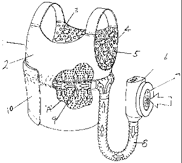
Figure 1 represents an embodiment of the invention in the form of a
vest and comprising a fan as a means to drive ambient air through a manifold
into the cavity of the garment.
Figure 2 is plan view of the body side of the vest illustrating the relative
disposition of the discrete elements on the substrate and perforations in the
said substrate.
Figure 3 is an enlarged view of area "X" in Figure 2 in which the discrete
elements comprise round protrusions.
Figure 4 is a representation of the cross-section of an embodiment of
the invention wherein the discrete elements within the cavity are disposed on
the gas -impermeable substrate.
Figure 5 is a representation of a cross-section of an embodiment of the
invention in the direction Y-Y' of Figure 2 wherein the discrete elements are
disposed either side of the gas- permeable substrate.
5
CA 02575757 2007-01-31
WO 2006/085998 PCT/US2005/025851
Figure 6 is a representation of a gas distribution manifold for use in an
embodiment of the invention.
Figure 7 is a representation of an alternative construction of a gas
distribution manifold for use in an embodiment of the invention.
Figure 8 shows graphical plots of heart rate (beats/minute) versus time
(hours) for a human subject in evaluation trials of an embodiment of the
invention.
Figure 9 shows graphical plots of body core temperature for a human
subject in evaluation trials of an embodiment of the invention.
DETAILED DESCRIPTION OF THE INVENTION
Referring to Figure 1 which represents a preferred embodiment of the
present invention the gas distribution cooling garment I comprises a
substantially gas impermeable substrate 2 attached around it's periphery to a
gas permeable substrate 3 to define a cavity, part of which is
representationally
shown by the cutaway section A. Substrate 3 has on its surface, which is
external to the cavity and which is proximate to the body of the wearer, a
plurality raised protrusions 4 in the form of discrete elements. Substrate 3
is
rendered gas-permeable by perforating the substrate between said raised
protrusions to give a plurality of holes 5 through which gas can vent from the
cavity and pass over the body of the wearer. In one embodiment, the cooling
gas is ambient air which is drawn by the fan 6 through optional filter 7 and
fed
through duct 8 to the air distribution manifold 9 and thence substantially
uniformly throughout the volume of the cavity to exit via the perforations 5.
The
cooling garment is held in close contact to the body of the wearer by a
fastening section 10 which may be fastened using "hook and loop" systems or
other suitable methods known in the art.
The direction of air-flow through the system is generally represented by
the sequence of block arrows which are included to aid comprehension of the
invention and are not to be interpreted as restricting the scope of the
invention.
Figure 2 is a plan view of one embodiment of the present invention
depicting the surface of the gas permeable substrate 3 that is worn proximate
to the body of the wearer. The distribution of the discrete elements 4 and the
perforations 5 are more clearly represented and are shown in detail in Figure
3
which is a pictorial enlargement of area "X" in Figure 2. Illustrative of one
embodiment of the present invention, Figure 3 shows the relative distribution
(not to scale) of the discrete elements 4 and the perforations 5 on the
surface
of the substrate 3. In the embodiment represented, the discrete elements are
6
CA 02575757 2007-01-31
WO 2006/085998 PCT/US2005/025851
shown as having circular cross-section in plan view which is not to be seen as
limiting the invention. The raised protrusions may comprise other shapes such
as cuboidal, conical, pyramidal, polyhedral, hemispherical or truncated
hemispherical. By "discrete elements" it is meant a plurality of individual
elements, that are substantially or essentially discontinuous or not
connected.
The discrete elements 4 are preferably soft and resilient but with limited
compressibility for optimum comfort and maintenance of air flow. The discrete
elements may comprise any material capable of maintaining space between
substrate layers, or between a substrate and the body of a wearer, but
preferably comprise a thermoplastic or thermosetting polymer selected from,
for example, but not limited to silicone, polyester, polyurethane, polyalkene,
polyamide, fluoropolymers or other similar materials known to one skilled in
the
art. Raised protrusions 4 may be applied to substrate 2 by any convenient
means such as extrusion or screen printing or other methods known, for
example, to one skilled in the art of surface coatings.
For optimal gas flow and cooling the raised protrusions preferably cover
50% or less of the area of the surface of substrate 3 which is proximate to
the
body of the wearer, a preferred coverage is less than 30% of the surface area
and a more preferred coverage is less than 20%. It has been discovered by the
inventor that, surprisingly, optimal cooling is achieved in systems wherein
the
height of the raised protrusions, preferably in the form of discrete elements,
4 is
in the range of about 1mm to 20mm, preferably in the range about 2mm to 10
mm and more preferably in the range about 2mm to 4mm. Preferably, the
raised protrusions 4 define a plurality of channels having a depth equivalent
to
the height of the protrusions, between the external surface of substrate 3 and
the wearer. The cooling gas which exits through perforations 5 flows through
the aforesaid channels and is distributed substantially uniformly over the
body
of the wearer.
The perforations 5 shown as circular in cross section may also be of
other cross-sections and are preferably uniformly distributed over the surface
of
substrate 3 to ensure uniform gas-flow over the body of the wearer. The cross-
sectional area of a single perforation is preferably equivalent to that of a
circular perforation having a diameter of between about 1 rnm and 2 mm. The
perforations should be sufficient in number for substrate 3 to have an air
permeability preferably of between about 10 and 100 I m-zs-' at a pressure
drop
of about 100 Pa and more preferably of between about 60 and 70 I m-2 s" at a
pressure drop of about 100 Pa .
7
CA 02575757 2007-01-31
WO 2006/085998 PCT/US2005/025851
Figure 4 shows enlarged detail of a cross-sectional view in the direction
of Y-Y" of Figure 2 of an embodiment of the invention. Substrates 2 and 3
define cavity 11 into which the cooling gas is passed from the gas
distribution
manifold (not shown). The raised protrusions 4 which comprise discrete
elements having a hemispherical profile are provided on the external surface
of
substrate 3, i.e. the surface which is external to cavity 11. When the garment
is
worn the protrusions 4 are in contact with the body of the wearer or in
contact
with an article of clothing, such as underwear or t-shirt, worn by the wearer.
Referring again to Figure 4 it will be seen that this embodiment
comprises a plurality of raised protrusion integral with the surface of
substrate
2, disposed internal to cavity 11. These are in the form of hemispherical
discrete elements 12 which are uniformly distributed over the surface of
substrate 2 within cavity 11. Raised protrusions preferably in the form of
discrete elements 12 cover preferably less than 50% of the area and, more
preferably, less than 30% of the surface of substrate 2 which is internal to
the
cavity. A function of the discrete elements 12 disposed within the cavity, is
to
act as spacer members to prevent the collapse of cavity 11, for example, when
heavy articles of clothing or a self contained breathing apparatus is worn
over
the cooling garment of the invention. A further function of the discrete
elements
12 is to aid in the uniform distribution of the cooling gas throughout the
cavity
11.
The height of the discrete elements 12 within the cavity is preferably in
the range of about 1mm to 20mm. To minimise the thickness of the vest, and
maximise its conformability and flexibility, and to ensure uniform
distribution of
the cooling gas through the cavity 11, a preferred height of the discrete
elements may range from about 2mm to 10mm. The discrete elements 12
located within the cavity may comprise any suitable material but preferred
materials are soft, resilient polymers having limited compressibility. The
polymers may be thermosetting or thermoplastic and may be selected from a
range of polymers such as silicones, polyurethanes, polyesters, polyamides ,
polyalkenes fluoropolymers or other polymers deemed suitable by one skilled
in the art, and may be applied to the supporting substrate by extrusion,
screen
printing or any suitable method known to one skilled in the art.
A further embodiment of the invention is shown in Figure 5 which is a
cross-section of a garment having an alternative arrangement of raised
protrusions in the form of discrete elements 12 within the cavity 11. In this
embodiment the discrete elements 12 are located on the internal surface of
substrate 3 and are positioned so as to be off-set from the protrusions 4
which
8
CA 02575757 2007-01-31
WO 2006/085998 PCT/US2005/025851
are situated on the opposite surface of substrate 3. In a further embodiment
the
discrete elements 12 on the internal surface of substrate 3 may be in
alignment
with the position of protrusions 4 on the external surface of the substrate,
while
maintaining airflow through the perforations 5.
Substrate 2 is preferably substantially gas impermeable; by
"substantially gas impermeable" is meant a substrate having less than about
10% of the gas permeability of the gas permeable second substrate. Preferred
substrates have an air permeability of less that 10 Im"2s' at pressure of 100
Pa.
Preferably, substrate 2 is also water vapour permeable. Substrate 3 may be a
gas impermeable layer which has been perforated, or may be an intrinsically
air
permeable layer such as a laminate of microporous PTFE, a tightly woven
textile, or a dense non-woven textile, with preferred constructions comprising
an air permeability in the range of between about 10 and 100 I m-2s"' as
previously taught herein. Where perforated, substrate 3 may be rendered
somewhat water-vapour-permeable by the perforations 5 but it is preferred that
the material of construction of substrate 3 is inherently water-vapour
permeable.
Substrates 2 and 3 may comprise single monolithic constructions or
may comprise a plurality of layers of different materials chosen to impart the
desired features to the substrates, such as air permeability and water vapour
permeability. A preferred construction is a laminate of knitted or woven
textile
and an expanded polytetrafluoroethylene membrane coated with a water
vapour permeable polymer. Such laminates are sold under the GORE-TEX
trade name by W.L. Gore and Associates Inc. Newark DE. Preferred water
vapour permeable materials for use in the substrates of the present invention
including both the gas impermeable substrate and the gas permeable
substrate, may be comprised of a layer of a water-vapour permeable polymer
such as polyurethane, polyester or microporous polyurethane or may comprise
such polymers coated on or laminated to a textile construction. Preferred
materials are those having water vapor evaporative resistance (Ret) values
less
than about 20 mz Pa W-' as measured according to ISO 11092. More preferred
materials are those having Ret values less than about 15m2 Pa W-' as
measured according to ISO 11092.
For maximum flexibility and conformability to the wearer's body-shape
the substrates 2 and 3 should be as thin as possible whilst having sufficient
robustness to withstand the stresses of use. Substrate 3 may comprise a
monolithic single layer construction or a plurality of layers or a laminate
comprising the same or different material that is chosen for substrate 2.
9
CA 02575757 2007-01-31
WO 2006/085998 PCT/US2005/025851
In an alternate construction of the present invention, a gas distribution
garment system is formed wherein the plurality of raised protrusions external
to
the cavity are not disposed directly on the external cavity surface. The
raised
protrusions external to the cavity surface are disposed on an additional
substrate that is interposed between the body of the wearer and the external
surface of the cavity. In a first embodiment of this alternate construction,
the
plurality of raised protrusions external to the cavity surface are disposed on
an
additional substrate located between the external cavity substrate and the
skin
of the wearer, and the raised protrusions are predominantly oriented towards
the skin. The additional substrate may be any suitable woven, non-woven or
knitted fabric which is air permeable. For example, a knitted undergarment
worn separately from the gas distribution garment may comprise a plurality of
raised protrusions disposed on the inside of the undergarment directed toward
the skin of the wearer. In this preferred embodiment, the additional substrate
comprising the raised protrusions is air permeable to enable the flow of air
from
the air permeable cavity substrate to flow through the additional substrate
into
close proximity with the wearer's skin.
In a second embodiment of this alternate construction, the additional
substrate comprising the plurality of raised external to the cavity is also
located
between the body of the wearer and the external surface of the cavity. In this
embodiment the plurality of raised protrusions are predominantly disposed on
the additional substrate in an orientation that is away from the skin. The
additional substrate may be any suitable woven, non-woven or knitted fabric
which is water vapor permeable such as, for example, a knitted undergarment
such as a T-shirt. In this embodiment, the additional substrate is water vapor
permeable to permit the evaporation of water from the skin into the stream of
air which is formed external to the cavity between the air permeable cavity
substrate and the additional substrate comprising the raised protrusions. In
this embodiment, the additional substrate is optionally air permeable. In an
embodiment of the alternate construction of the present invention, the
additional substrate may be permanently affixed to one or both of the
substrates that form the cavity, or the additional substrate may be detachably
affixed to the substrates, or the additional substrate may be separate from
the
substrates that form the cavity.
The cavity formed by the substrates is adapted for connection with a
gas supply so that gas flows into the cavity and exits the cavity through the
gas
permeable substrate. A preferred means for such adaptation comprises a gas
distribution manifold, substantially hollow in cross section, which is in
fluid
CA 02575757 2007-01-31
WO 2006/085998 PCT/US2005/025851
connection with the gas supply and comprises a series of perforations to allow
gas to be distributed within at least part of the cavity. Figure 6 is a
representation of the construction of a gas distribution manifold for use in
an
embodiment of the invention. The manifold of Figure 6 comprises a hollow
elongate member 13 which is substantially rectangular in cross-section, though
it should be understood that other cross-sectional shapes are suitable for use
in
the present invention Hollow member 13 is provided with a series of
perforations 14 along the sides 15 and 16 and a gas feed duct 17. In use
hollow member 13 is placed in the cavity of the garment with the duct 17
external to the cavity. The cooling gas is fed through the lumen 18 of duct 17
and is distributed into the cavity of the garment through perforations 14.
Figure 7 is a representation of an alternative and preferred construction
of a gas distribution manifold for use in the garment of the invention and
corresponds to item 9 in Figure 1. The construction comprises two hollow
elongate members 19 and 20 which are substantially cylindrical in cross-
section
and have a series of perforations 21 along edges 22, 23, 24,and 25. Hollow
members 19 and 20 are connected to gas feed duct 26 by union piece 27 and
the ends members 19 and 20 remote from union piece 27 are closed off by
blanking pieces 28 and 29.
In use, members 19 and 20 are preferably placed in the cavity of the
garment such that one member is in the area of the garment which covers the
front of the torso of the wearer and the other member is in the back area of
the
garment. Gas feed duct 26 is the representative embodiment is external to the
cavity of the garment. Cooling gas fed into duct 26 is fed into both members
19
and 20 and is distributed into the cavity through perforations 21.
The members 19 and 20 maybe constructed of any suitable material
known to one skilled in the art but for optimal comfort for the wearer the
material should be soft and flexible and preferably resilient with only a
slight
degree of compressibility. Suitable materials include elastomeric materials
such
as polyurethane, polyester, or synthetic rubbers such as EPDM or SBR. It is
preferable for the material to have a hardness in the range of 55-65 Shore A.
11
CA 02575757 2007-01-31
WO 2006/085998 PCT/US2005/025851
EXAMPLES
EXAMPLE 1
To demonstrate the efficacy of an embodiment of the invention a
garment was constructed according to the teaching of this specification and
its
cooling effectiveness evaluated whilst being worn by a human subject walking
on a tread-mill.
The first and second substrates comprised a laminate of Basofil spun
bonded non-woven textile and expanded polytetrafluoroethylene having an air-
impermeable water vapour permeable coating with a plurality of foamed
silicone rubber protrusions uniformly distributed on the Basofil surface. The
laminate is available from W.L. Gore and Associates GmbH, Putzbrunn,
Germany under the trade name Airlock Part No. AIRL 002000. The silicone
rubber protrusions are approximately 3mm in height and cover an area of
approximately 13% of the surface of the laminate.
Two pieces of AirlockO AIRL 002000 laminate were cut and sized
according to Figure 2 to give a body coverage of about 0.45m2 . The laminate
corresponding to the second substrate of the invention was perforated with a
1.34 mm diameter needle to give a grid pattern of holes on an approximately
6mm by 10mm spacing. The air permeability of the laminate resulting from the
perforations was about 60 I.m"2s-' at a pressure drop of about 100 Pa.
The cut pieces of laminate were oriented according to the arrangement
in Figure 4 and attached round their periphery by sewing, thereby forming a
cavity. A gas distribution manifold of the general arrangement of Figure 7 was
formed from two lengths of 25 mm inside diameter cylindrical cable duct (Part
No. 364-3458 from RS Components Ltd. Corby, Northants, England)
corresponding to members 19 and 20 of Figure 7. The length of each member
was about 460mm. A uniform series of approximately 4mm diameter holes
were drilled in the surfaces of the duct corresponding to surfaces 22, 23, 24
and 25 of Figure 7 to give 92 holes per member. The ends of the duct within
the cavity were sealed with blanking pieces and the other ends terminated in a
union piece and gas entry duct corresponding to 27and 26 respectively of
Figure 7. An electrically powered fan, (Part No. U97EM-012KK-3 from Acal
Radiatron, Egham, Surrey, England) was connected to the gas duct to
complete the assembly. During the evaluation trials, for convenience, the fan
was powered from a bench mounted power supply unit adjusted to provide
about 15 Volts dc to the fan. With this set up the airflow from the fan was
calculated by measuring the pressure drop across the fan and comparing this
12
CA 02575757 2007-01-31
WO 2006/085998 PCT/US2005/025851
with the pressure drop versus flow from the manufacturers data sheet for the
fan. The flow was ascertained to be about 10 litres/sec.
For the evaluation trials the subject was clad in the following manner.
The subject was dressed in a cotton T-shirt and cotton briefs next to the
skin.
The cooling garment of Example 1 was provided over the T-shirt. Over the
cooling garment, a British Army Mk IV protective suit was provided. Finally,
on
top of the protective suit, a British Army MK I Fragmentation vest was
provided. The feet were covered in socks and heavy boots, and the hands
were covered with lightweight cotton gloves under rubber gloves. A respiration
mask was placed on the face of the subject.
Three evaluation trials were performed in the following manner.
Trial 1 - Subject clad as above with fan running (i.e. cooling in
operation).
Trial 2 - Subject clad as above with fan switched off (i.e. no cooling).
Trial 3 - Subject clad as above but cooling garment removed (i.e.
garment ensemble as currently used by military personnel remained).
The subject was tasked to walk on a tread-mill set at a linear speed of
about 4.5 km/hr and the subject's body core temperature and heart rate _
monitored and recorded. The duration of each trial consisted of periods of
about 100 minutes of walking followed by rest periods of about 30 minutes. The
evaluation trials were carried out in an environmentally conditioned room at
an
ambient temperature of approximately 35 C and a relative humidity of 50%.
The plot of heart rate versus time and the plot of body core temperature
versus time for all three trials are shown respectively in Figures 8 and 9.
Referring to Figure 8, the plot of heart rate (beats/minute) versus time
(hours),
shows the highly significant cooling effect of the garment of the invention.
The
plot of heart rate against time for the subject with the garment in cooling
mode
("cooling" plot) corresponding to Trial 1 shows a slight overall rise in heart
rate
(from approximately 80 beats per minute to approximately 100 beats per
minute) throughout the duration of the trial. The regular peaks in the plot
correspond to the exercise periods but, with the cooling in operation, the
rate
drops back to substantially the base level during the rest periods. In
contrast,
however, the heart rate plots for the "no cooling" and the "no vest" modes
(Trials 2 and 3) result in regular rise in heart rate throughout the trials
from
approximately 80 beats per minute to highly undesirable rates of 160 beats per
minute.
The close correlation between the plots for Trials 2 and 3 does however
demonstrate another highly desirable feature of the invention i.e. that even
13
CA 02575757 2007-01-31
WO 2006/085998 PCT/US2005/025851
when the garment is worn without it being cooled it adds little or nothing to
the
thermo-physiological load on the wearer compared with the clothing ensemble
not including the cooling garment.
The body core temperature plots in Figure 9 further confirms the
effectiveness of the cooling garment of the invention. The "cooling" plot
shows
the very small rise (less than about 0.5 C) in the subject's body core
temperature. In contrast, the "no cooling" and "no vest" plots corresponding
to
Trials 2 and 3 show highly undesirable increases of almost 2 C. However, as
with the heart rate plots, the body core temperature plots demonstrate the
negligible thermo-physiological loading characteristics of the garment when
worn without the cooling in operation.
The objectives of the invention are also clearly achieved by the garment
of the above example. Whereas in the foregoing trials the fan was powered by
a bench mounted power supply unit it has been shown that a battery powered
fan could be used and the same air flow rates achieved. The fan of the
example was replaced by a fan requiring only a 5 Volt dc supply (Part
no.U97LM-005K1 from Acal Radiatron, Egham, Surrey, England) and the
replacement fan powered by a nominally rated 6.4 Volt battery with an under-
load voltage of 5.0 Volts (Part no. U3356H/2/7, from Ultralife Batteries Ltd.
Abingdon, Oxfordshire, England.) The fan gave an output of about 6 litres/sec
for over 9 hours.
The garment of the example with the fan and battery attached weighed
approximately 2.1 kg, which is considerably less than the 3kg target for a
lightweight system.
EXAMPLE 2
Cooling
To evaluate the cooling power of the cooling garment prepared
substantially according to Example 1, it was subject to Thermally Instrumented
Manikin testing by The Cord Group Ltd., Dartmouth, Nova Scotia, Canada. The
cooling garment was tested in combination with a standard British Army Mk IV
protective suit as used in the foregoing Example 1 and under the various
conditions as detailed in the following Table 1. Testing was carried out in a
temperature and humidity controlled room with an ambient temperature set at
35 C and relative humidity set 50%. Details of the test methodology are as
follows.
14
CA 02575757 2007-01-31
WO 2006/085998 PCT/US2005/025851
Test Method
The evaluation of cooling vest prototypes using UK standard suit
ensemble was conducted using a Thermal Instrumented Manikin Test System.
During the testing, environment temperature, skin temperature and power
consumption were recorded.
The Thermal Manikin Test System consists of a hollow aluminum
manikin equipped with temperature sensors and electric heaters connected to a
computer system. The manikin was dressed in the human-use apparel to be
tested and placed in an appropriate environment. The computing equipment
controlled the heaters to maintain the skin of the manikin at a set
temperature
and measured the electrical power required to do so. This power is equivalent
to the heat that escaped through the clothing due to the temperature
difference
across it. The power and the temperature difference were then used, along with
the known surface area of the manikin to calculate the thermal resistance
offered by the apparel.
The thermal performance of a garment was evaluated by unmanned
tests on the whole garment under conditions identical or similar to actual
operating conditions. The system employed a life-sized watertight manikin
capable of being heated to and maintained at a.selected temperature.
The system comprised a Thermally Instrumented Manikin (TIM), a
control module, a computer, environmental temperature sensors and cables
connecting these components. The manikin was in a shape of human
proportions to fit inside the test garment. The combinations of the aluminum
shell of the manikin and the output of heaters inside it provided for an
approximately uniform temperature over the manikin surface. This temperature
is sensed by sensors embedded in the manikin's shell and is then passed to
the control module.
The control module housed the programmed data acquisition system,
the heater relays and other circuit components. The data acquisition system
received data from the temperature sensors on the manikin and controlled the
heater relays so that the manikin surface temperature remains constant. It
also
measured the environment temperature and the power applied to the manikin
and was programmed with the surface area of the manikin. With this
temperature, power and area data, it calculated the insulation value of the
garment and passed this, along with other pertinent data to the computer. The
computer acted as a control and display terminal and post-processor.
The following clothing combination was used for testing. The manikin
was first covered in a shirt with long sleeves and trousers assembled into a
CA 02575757 2007-01-31
WO 2006/085998 PCT/US2005/025851
coverall (skin) made of an interlock knit (high stretch), white 100% cotton
textile. Tubes for the distribution of water were sewn into the garment.
Depending on the test set-up as described in Manikin Set Up, A through E, of
Table 1 cooling garments prepared according to Example 1 (two styles) were
selected and optionally provided over the coverall. One style of cooling
garment comprised a single entry port manifold (Fig. 6), and a second style of
cooling garment was provided with a split manifold (Fig. 7). An outer layer
comprising a UK Standard protective suit ensemble top and bottom, and a Mk I
ballistic vest, was provided over the cooling garment, or depending on test
conditions, directly over the coverall (skin). Garment openings were secured
as follows. Arm cuffs were tucked and secured with elastic straps; front
zippers
were secured to the top; and bottom of legs were secured with elastic straps.
Tensioning straps on the ballistic vest were secured.
The manikin was lifted into a vertical position and suspended in the test
chamber hanging from a head bolt with feet lightly touching the floor.
Environmental sensors were suspended around the manikin to detect the
environment temperature. The manikin temperature was set at about 35.0 C.
The ambient temperature of the chamber was set at about 35 C and actual
temperature was measured at about 34.16 - 34.31 C. The ambient relative
humidity of the chamber was set at about 50% about and measured at about
48.5 - 56.0 %. Water, fed to the cotton garment by way of the tubes, was
provided to simulate wetting by sweat. A warm-up period was provided to allow
the manikin to reach the set temperature and go into test period. The long-
term
power was monitored for all calculated sections until steady state condition
was
reached, and the test was restarted.
The steady state long term power results of the thermal instrumented
manikin with and without gas distribution vests of the present invention and
standard British protective suit ensemble is as follows.
16
CA 02575757 2007-01-31
WO 2006/085998 PCT/US2005/025851
Table 1.
Air Long Term Power (watts)
Manikin Description
Set Up Flow I/s Front* Back** Arms Legs Overall
A Protective suit 0 3.42 1.10 23.88 41.30 69.71
with ballistic vest,
skin wet, no
cooling vest, no
coolin baseline
B Protective suit 0 2.70 1.17 21.40 42.92 68.19
with ballistic vest,
skin wet, split
duct cooling vest,
no cooling
C Protective suit 9.28 41.45 49.74 24.78 102.39 218.36
with ballistic vest,
skin wet, split
duct cooling
vest,cooling @
15 v dc
D Protective suit 9.36 46.17 49.51 32.46 93.68 221.82
with ballistic vest,
skin wet,CZ15
single entry
cooling vest,
cooling 15 v
E Same as test 8.71 44.79 47.45 26.67. 94.59 213.50
number D with
backpack added
with 102 lbs
contained in pack
Front *- Consists of chest and abdomen sections of the manikin
Back Consists of back and buttocks sections of the manikin
Table 1 illustrates the significant overall cooling power of the cooling
garment of the present invention when energised in cooling mode.
Furthermore, a comparison of the results of Manikin Set Ups A and B
demonstrates the minimal additional thermal stress added to the Thermally
Instrumented Manikin by the cooling garment system of the invention when the
garment is not energised for cooling.
Conformability
Conformability of the garment of the present invention was tested and
compared with a mesh spacer material representative of those used by
garments of the prior art. A sample comprising Airlock@ Laminate AIRL 02000
was prepared according to the air permeable second substrate of Example 1
having a plurality of protrusions and perforations, and was tested and
compared with spacer material from Mueller Textile Germany, Mueller Part no.
5911.
17
CA 02575757 2007-01-31
WO 2006/085998 PCT/US2005/025851
20 Test Method
The test method used was performed substantially as described
in ASTM D 4032 - 94 (as re-approved in 2001) - Standard Test Method for
Stiffness of Fabric by the Circular Bend Procedure, with the following
modifications. The size of the test sample was 4 inches by 4 inches (100mm by
25 100mm) an Instron Model 1011 tensile/compression tester operating with
Instron Series 9 software replaced the force measurement gauge; and the
plunger speed was set at 500mm/min.
The AirlockO laminate was tested in three different modes, as follows:
Trial 1: laminate was tested on its own with the protrusions facing
30 downwards in contact with the test platform;
Trial 2: laminate was tested on its own with the protrusions facing
upwards in contact with the plunger;
Trial 3: laminate was tested in combination with an 84g/m2 woven
polyester face fabric to simulate a garment construction of the invention .
35 Five samples of each material were subjected to the conformability test
and results are summarised below, in Table 2.
Table 2.
Material: AIRL 02000 AIRL 0200 AIRL 02000 Spacer material
(Trial#) (Trial 1) (Trial 2) (Trial 3) (Mueller 5911)
Average peak
force (kg) 0.010 0.011 0.009 0.049
The differences between the conformability of the materials of the
present invention compared with other spacer material are clearly
demonstrated by this test. Materials having lower average peak force values
are deemed more conformable than materials having higher average peak
force values. Thus, preferred embodiments of the present invention comprise
a conformability peak force value of preferably less than or equal to 0.03 kg,
more preferably less than or equal to 0.02 kg, and further preferred, less
than
or equal to 0.01 kg, for a substrate comprising a plurality of raised
protrusions
on a substrate surface, when tested according to the method provided herein.
Whereas the foregoing examples are demonstrative of a specific
embodiment of the invention it should not be deemed to be limiting in scope.
18
CA 02575757 2007-01-31
WO 2006/085998 PCT/US2005/025851
One skilled in the art will select other embodiments, designed for specific
end
uses. For example an embodiment of the invention intended for use by fire
fighters and other operatives subjected to fire or other high temperature
situations may comprise non-melting and non-flammable materials.
While particular embodiments of the present invention have been
illustrated and described herein, the present invention should not be limited
to
such illustrations and descriptions. It should be apparent that changes and
modifications may be incorporated and embodied as part of the present
invention within the scope of the following claims.
19