Language selection

Search

Patent 2575775 Summary

Third-party information liability

Some of the information on this Web page has been provided by external sources. The Government of Canada is not responsible for the accuracy, reliability or currency of the information supplied by external sources. Users wishing to rely upon this information should consult directly with the source of the information. Content provided by external sources is not subject to official languages, privacy and accessibility requirements.

Claims and Abstract availability

Any discrepancies in the text and image of the Claims and Abstract are due to differing posting times. Text of the Claims and Abstract are posted:

  • At the time the application is open to public inspection;
  • At the time of issue of the patent (grant).
(12) Patent Application: (11) CA 2575775
(54) English Title: SINGLE-BLADE VACUUM PUMP
(54) French Title: POMPE A VIDE A UNE AILETTE
Status: Deemed Abandoned and Beyond the Period of Reinstatement - Pending Response to Notice of Disregarded Communication
Bibliographic Data
(51) International Patent Classification (IPC):
  • F4C 18/344 (2006.01)
(72) Inventors :
  • SCHNEIDER, WILLI (Germany)
  • THOMA, MARTIN (Germany)
  • PFITZER, FRIEDHELM (Germany)
(73) Owners :
  • JOMA-HYDROMECHANIC GMBH
(71) Applicants :
  • JOMA-HYDROMECHANIC GMBH (Germany)
(74) Agent:
(74) Associate agent:
(45) Issued:
(86) PCT Filing Date: 2005-04-20
(87) Open to Public Inspection: 2006-01-19
Examination requested: 2010-03-25
Availability of licence: N/A
Dedicated to the Public: N/A
(25) Language of filing: English

Patent Cooperation Treaty (PCT): Yes
(86) PCT Filing Number: PCT/EP2005/004209
(87) International Publication Number: EP2005004209
(85) National Entry: 2007-02-01

(30) Application Priority Data:
Application No. Country/Territory Date
10 2004 034 925.8 (Germany) 2004-07-09

Abstracts

English Abstract


The invention relates to a single-blade vacuum pump comprising a pot-shaped
housing (12), a rotor (18) mounted in the housing in such a way that it can be
eccentrically rotated, a blade (20) mounted in the rotor in such a way that it
can be orthogonally displaced in relation to the rotational axis, and a
housing cover which is used to close the working regions separated by the
blade (20). According to the invention, the rotor (18) at least partially
consists of sintered metal.


French Abstract

L'invention concerne une pompe à vide à une ailette, qui comprend un carter de pompe (12) en forme de creuset, un rotor (18) monté de manière rotative et excentrique dans le carter, une ailette (20) logée mobile dans le rotor orthogonalement à l'axe de rotation, ainsi qu'un couvercle de carter fermant les espaces de travail séparés par l'ailette (20). Selon l'invention, le rotor (18) est constitué au moins partiellement de métal fritté.

Claims

Note: Claims are shown in the official language in which they were submitted.

8
Claims
1. A single-blade vacuum pump (10) comprising a pot-shaped
housing (12), a rotor (18) which is eccentrically rotated in
the housing (121), a blade (20) which in the axis of
rotation is rotatably mounted in the rotor orthogonally in
relation to the axis of rotation, and a housing cover
closing the expansion chambers separated by the blade (20),
characterized in that the rotor (18) at least partially
consists of sintered metal.
2. A single-blade vacuum pump as defined in claim 1,
characterized in that the rotor (18) comprises a rotor axis
(22) and a rotor housing (24) placed upon the rotor axis
(22).
3. A single-blade vacuum pump as defined in claim 2,
characterized in that the rotor axis (22) consists of
sintered metal.
4. A single-blade vacuum pump as defined in claim 2 or 3,
characterized in that the rotor housing (24) consists of
synthetic material.

9
5. A single-blade vacuum pump as defined in claim 4,
characterized in that the synthetic material is a
polyetheretherketone (PEEK), polyether sulfide (PES),
syndiotactic polystyrol (SPS) or a polyphenyl sulfide (PPS).
6. A single-blade vacuum pump as defined in one of the claims 2
to 5, characterized in that the rotor housing (24) is
plugged onto the rotor axis (22).
7. A single-blade vacuum pump as defined in claim 6,
characterized in that the rotor axis (22) for accommodating
the rotor housing (24) comprises at least two pins (36),
which diminish parallel to the axis of rotation.
8. A single-blade vacuum pump as defined in claim 7,
characterized in that the rotor housing (24) comprises two
sleeves (46), which can be plugged onto the pins (36).
9. A single-blade vacuum pump as defined in claim 7 or 8,
characterized in that the pins (36) extend at least over
part of the height of the blade (20).
10. A single-blade vacuum pump as defined in claims 8 and 9,
characterized in that the other part (58) of the sleeves
(46), which is not penetrated by the pins (36), is stiffened
by means of bracings (60).

11. A single-blade vacuum pump as defined in one of the above
claims, characterized in that the rotor (18) is hollow.
12. A single-blade vacuum pump as defined in one of the claims 2
to 11, characterized in that the rotor axis (22) and/or the
rotor housing (24) have cavities.
13. A single-blade vacuum pump as defined in one of the claims 2
to 12, characterized in that the rotor axis (22) has three
cavities.
14. A single-blade vacuum pump as defined in one of the
above claims, characterized in that only sections of the
rotor (18) consist of sintered metal.

Description

Note: Descriptions are shown in the official language in which they were submitted.


CA 02575775 2007-02-01
WO 2006/005380 PCT/EP2005/004209
Title: Single-Blade Vacuum Pump
Description
The invention relates to a single-blade vacuum pump with a pot-
shaped housing, a rotor which is eccentrically rotated in the
housing, a blade which in the axis of rotation is rotatably
mounted in the rotor orthogonally in relation to the axis of
rotation, and a housing cover closing the expansion chambers
separated by the blade.
Vacuum pumps with a structure of this type are known. As a rule,
said pumps comprise a housing consisting of metal wherein a rotor
is rotatably mounted and in which the expansion chambers are
formed. The rotor, for example, is put into motion by the engine
of a motor vehicle. It also is known that said rotor consists of
metal and, in particular, sinter metal. Because of the high
weight of the rotor, said rotor has a large mass moment of
inertia as a result of which the power consumption of the vacuum
pump is undesirably high.
It is the object of the present invention to provide a vacuum
pump, especially a single-blade vacuum pump, which has a lower
power consumption.

CA 02575775 2007-02-01
WO 2006/005380 PCT/EP2005/004209
2
In view of the foregoing, the problem is solved in accordance
with the invention by means of a single-blade vacuum pump as
mentioned hereinabove in that the rotor at least partially
consists of sintered metal.
The invention consists in producing only sections of the rotor
from a different metal of a lower weight. Consequently, the
overall weight of the rotor is reduced and the mass moment of
inertia is diminished. By this one achieves a reduced power
consumption of the vacuum pump, which is lower than with
conventional units. In particular, those components of the
rotor, which must transmit large moments as before are made of
metal, whereas sections of the rotor may consist of a different
material, which is less subjected to stress.
In one improvement, it is proposed that the rotor comprises a
rotor axis and a rotor housing placed upon said rotor axis. It
is the task of the rotor axis to initiate the torque required for
driving the pump and to start rotating the rotor with blade. It
is the object of the rotor housing to control and guide the
blade.
Since the driving forces and the moments, which have an effect on
acceleration and delay, must be supported mainly by the rotor
axis, said axis consists of sintered metal. When controlling the
blade, these types of forces and moments play a subordinate role,
wherein sealing problems come to the fore. Therefore, the rotor
housing, according to the invention, is made of synthetic
material. Synthetic materials, especially when paired with a

CA 02575775 2007-02-01
WO 2006/005380 PCT/EP2005/004209
3
metal, in this case a blade made of metal, have excellent
tribological properties as a result of which frictional forces
can be reduced to a minimum, which also counters excessive
heating.
The rotor housing may also have the objective of sealing the two
expansion chambers against one another in that the rotor housing
is located adjacent to the internal peripheral wall. If the pump
housing consists of metal and the rotor housing of synthetic
material, the frictional forces will be reduced and good sealing
properties will be achieved.
Preferred embodiments provide the following synthetic materials
for the rotor housing: Polyetheretherketone (PEEK), polyether
sulfide (PES), syndiotactic polystyrol (SPS) or a polyphenyl
sulfide (PPS). These synthetic materials are extremely resistant
to abrasion and to lubricants.
A simple installation of the rotor is achieved in that the rotor
housing is plugged onto the rotor axis, especially in the
direction of the axis. The plug connections are produced easily
and in particular without tools. Furthermore, during the
operation of the vacuum pump, there is no reaction of forces in
or against the plug-in direction, so that there is no concern for
the plug connection becoming loose.
A preferred variant of the invention provides that, in order to
attach the rotor housing, the rotor axis comprises at least two

CA 02575775 2007-02-01
WO 2006/005380 PCT/EP2005/004209
4
pins diminishing parallel to the axis of rotation. By contrast,
the rotor housing has two sleeves which can be placed upon the
pins. The shape of the pins and sleeves preferably is selected
in such a way that not only the rotor housing is held safely by
the rotor axis, but the guiding forces holding the blade are
supported via the sleeves by the pins.
For this purpose, the pins extend at least over part of the
height of the blade. In order to extend, hold securely, and
control the blade even with relatively short pins, which, for
example, extend over a height of 10% - 20% of the blade, the
other part of the sleeve, which is not penetrated by the pin, is
stiffened by means of braces. This saves material and
consequently weight as well.
Other advantages, characteristics, and details of the invention
are specified in the subordinate claims and in the following
description in which, by referring to the drawing, a preferred
embodiment is described in detail. Further, the characteristic
elements represented in the drawing and mentioned in the
description and in the claims can be fundamental to the invention
individually or in any combination.
Of the drawing:
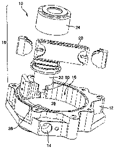
Figure 1 shows an exploded view of the vacuum pump;
Figure 2 shows a perspective view of the blade; and

CA 02575775 2007-02-01
WO 2006/005380 PCT/EP2005/004209
Figure 3 shows a perspective presentation of the blade, shown in
part as a section.
Figure 4 shows a perspective view of the rotor housing with
inserted blade.
Figure 1 shows the vacuum pump with the overall reference symbol
wherein the housing 12 is represented without cover. The
housing 12 has a suction connection 14, which ends in an interior
16. This interior 16 contains a rotor with the overall
designation 18, wherein a blade 20 is rotatably mounted
orthogonally to the axis of rotation 21. The rotor 18 is
structured in two parts and comprises a rotor axis 22 and a rotor
housing 24. The rotor axis 22 passes through the housing 12,
especially a base 26 of the interior 18 via a drive opening 28
and with a rectangular section 30 at the rear projects from the
housing 12 via which said section (by means of a drive, which is
not shown) is put into rotation. The drive opening 28 is
provided with suitable sealants, so that neither lubricant is
able to leak nor air and/or dirt able to enter the interior 16.
Section 30 continues in a cylindrical section 32 with circular
cross-section, as is shown in Figure 2. Section 32 is connected
to a disk 34 from which the pins 36 extend in the direction of
the axis. The pins 36 are provided with recesses 38, so that
they essentially are formed by a wall 40, which has the shape of
the letter "D." Between the two pins 36, there is a running
surface 42, which is formed by part of the surface of the disk

CA 02575775 2007-02-01
WO 2006/005380 PCT/EP2005/004209
6
34. This running surface 42, abuts on a narrow side of the blade.
Further, a lubricant bore 44 ends in this running surface 42, via
which the running surface 42 and other running surfaces or
generally the interior 16 and/or the blade 20 are supplied with
lubricant.
Figure 3 shows a rotor housing 24, which comprises a vertical
section corresponding to an upside-down letter "U," which is open
towards the bottom. The rotor housing 24 has two sleeves 46
which are interconnected via a bridge 48. These sleeves 46 are
largely hollow, which is evident from Figure 4. The two sleeves
46 between themselves define two running surfaces 50 on which the
broad side of the blade 30 abuts. Ultimately, the section of the
underside of the bridge 48, which is located between the two
sleeves 46, forms a running surface 52 on which the second narrow
side of the blade abuts. The blade 20 thus is controlled via the
running surfaces 42, 50, and 52, and can be moved to both sides
of the longitudinal axis of the blade 54.
As is evident from Figure 4, the sleeves 46 comprise a first
section 56 in which the pins 36 can be inserted. A second
section 58 is connected to this first section 56, which also is
hollow, in which, however, the bracings 60 extend, which in
particular are arranged in a radial direction. The sleeves 46
therefore are mainly formed by walls, which essentially are
shaped like a"D." The mass of the rotor housing 24 therefore is
relatively small.

CA 02575775 2007-02-01
WO 2006/005380 PCT/EP2005/004209
7
Since the pins 36 are hollow, the mass is determined by the
weight of walls 40. With a preferred embodiment, the rectangular
section 30 is hollow as a result of which its mass is reduced.
Said cavity extends from the free end of the section 30 to the
lubricant hole 44. Said cavity is limited by the essentially
rectangular wall of the section 30.
In an improvement of the invention, the lateral parts of the
cylindrical section 32, which project over the section 30, are
hollow, wherein these cavities extend to the underside of the
disks 34 and on each side have an essentially D-shaped cross-
section. Consequently, the mass of the section 32 is reduced.
Another reduction of weight of the rotor 18 is achieved in that
one part of the rotor 18 consists of sintered metal, while the
other part consists of synthetic material. In particular, the
rotor housing 24 consists of synthetic material. As a result,
tribological optimal pairings of the running surfaces 50 and 52
can be created with the surfaces of the blade 20.

Representative Drawing
A single figure which represents the drawing illustrating the invention.
Administrative Status

2024-08-01:As part of the Next Generation Patents (NGP) transition, the Canadian Patents Database (CPD) now contains a more detailed Event History, which replicates the Event Log of our new back-office solution.

Please note that "Inactive:" events refers to events no longer in use in our new back-office solution.

For a clearer understanding of the status of the application/patent presented on this page, the site Disclaimer , as well as the definitions for Patent , Event History , Maintenance Fee  and Payment History  should be consulted.

Event History

Description Date
Revocation of Agent Requirements Determined Compliant 2021-04-01
Application Not Reinstated by Deadline 2012-04-20
Time Limit for Reversal Expired 2012-04-20
Revocation of Agent Requirements Determined Compliant 2012-01-17
Inactive: Office letter 2012-01-13
Inactive: Office letter 2012-01-11
Revocation of Agent Request 2011-12-13
Deemed Abandoned - Failure to Respond to Maintenance Fee Notice 2011-04-20
Amendment Received - Voluntary Amendment 2010-07-13
Letter Sent 2010-04-15
Request for Examination Received 2010-03-25
All Requirements for Examination Determined Compliant 2010-03-25
Request for Examination Requirements Determined Compliant 2010-03-25
Revocation of Agent Requirements Determined Compliant 2008-11-14
Inactive: Office letter 2008-11-14
Inactive: Office letter 2008-11-13
Amendment Received - Voluntary Amendment 2008-06-09
Inactive: IPRP received 2008-02-21
Inactive: Declaration of entitlement - Formalities 2007-12-07
Inactive: Cover page published 2007-04-19
Inactive: Courtesy letter - Evidence 2007-04-10
Inactive: Notice - National entry - No RFE 2007-04-04
Application Received - PCT 2007-02-26
National Entry Requirements Determined Compliant 2007-02-01
Application Published (Open to Public Inspection) 2006-01-19

Abandonment History

Abandonment Date Reason Reinstatement Date
2011-04-20

Maintenance Fee

The last payment was received on 2010-03-12

Note : If the full payment has not been received on or before the date indicated, a further fee may be required which may be one of the following

  • the reinstatement fee;
  • the late payment fee; or
  • additional fee to reverse deemed expiry.

Patent fees are adjusted on the 1st of January every year. The amounts above are the current amounts if received by December 31 of the current year.
Please refer to the CIPO Patent Fees web page to see all current fee amounts.

Fee History

Fee Type Anniversary Year Due Date Paid Date
Reinstatement (national entry) 2007-02-01
Basic national fee - standard 2007-02-01
MF (application, 2nd anniv.) - standard 02 2007-04-20 2007-03-22
MF (application, 3rd anniv.) - standard 03 2008-04-21 2008-03-17
MF (application, 4th anniv.) - standard 04 2009-04-20 2009-03-17
MF (application, 5th anniv.) - standard 05 2010-04-20 2010-03-12
Request for examination - standard 2010-03-25
Owners on Record

Note: Records showing the ownership history in alphabetical order.

Current Owners on Record
JOMA-HYDROMECHANIC GMBH
Past Owners on Record
FRIEDHELM PFITZER
MARTIN THOMA
WILLI SCHNEIDER
Past Owners that do not appear in the "Owners on Record" listing will appear in other documentation within the application.
Documents

To view selected files, please enter reCAPTCHA code :


To view images, click a link in the Document Description column (Temporarily unavailable). To download the documents, select one or more checkboxes in the first column and then click the "Download Selected in PDF format (Zip Archive)" or the "Download Selected as Single PDF" button.

List of published and non-published patent-specific documents on the CPD .

If you have any difficulty accessing content, you can call the Client Service Centre at 1-866-997-1936 or send them an e-mail at CIPO Client Service Centre.

({010=All Documents, 020=As Filed, 030=As Open to Public Inspection, 040=At Issuance, 050=Examination, 060=Incoming Correspondence, 070=Miscellaneous, 080=Outgoing Correspondence, 090=Payment})


Document
Description 
Date
(yyyy-mm-dd) 
Number of pages   Size of Image (KB) 
Description 2007-01-31 7 226
Abstract 2007-01-31 2 86
Drawings 2007-01-31 3 76
Claims 2007-01-31 3 67
Representative drawing 2007-04-17 1 19
Reminder of maintenance fee due 2007-04-03 1 109
Notice of National Entry 2007-04-03 1 192
Reminder - Request for Examination 2009-12-21 1 125
Acknowledgement of Request for Examination 2010-04-14 1 179
Courtesy - Abandonment Letter (Maintenance Fee) 2011-06-14 1 173
PCT 2007-01-31 4 122
Correspondence 2007-04-03 1 26
Correspondence 2007-12-06 3 97
PCT 2007-02-01 5 128
Correspondence 2008-10-07 17 614
Correspondence 2008-11-12 1 18
Correspondence 2008-11-13 1 26
Correspondence 2012-01-10 1 18
Correspondence 2012-01-12 1 19
Correspondence 2011-12-12 19 699