Note: Descriptions are shown in the official language in which they were submitted.
CA 02576345 2007-02-07
WO 2006/008546 PCT/GB2005/002889
1
Nailer device
The invention to which this application relates is a portable
reciprocal action nailer power tool, also known as a nail gun.
Although the following description refers almost exclusively to
use of a power tool to drive nails into a substrate, it will be
appreciated by persons skilled in the art that the present
invention can be used to drive other components or securing
means, such as rivets, bolts, fasteners and / or the like.
In order to fix a material to a substrate; nails are typically struck
to pass through the material and into the substrate, thereby
securing the same. It is possible for a user to strike a nail with
repeated blows from a hammer, although this can be quite tiring
and time-consuming.
In industry, nailer devices are often used. Conventional nailer
devices are usually pneumatic single-strike action devices,
whereby the nail is placed in the device and struck with one
blow to force the nail into position. This arrangement allows the
device to be fitted with a cartridge containing a plurality of
nails, the user moving the device after each strike to insert nails
successively. However, the force required to insert a nail in a
single strike is often high, and pneumatic devices may require
compressors for the air supply, or expensive gas cartridges. This
means that conventional nailer devices are typically large and
heavy, and require mains power for practical operation to
achieve the aforementioned force. They are also not suitable for
more fragile surfaces, which may break under the stress caused
by the high force of the single strike action. In addition, as the
device shoots nails with high force, it may be very dangerous in
the hands of an inexperienced user.
CA 02576345 2007-02-07
WO 2006/008546 PCT/GB2005/002889
2
Furthermore, conventional nailer devices typically do not have a
power level setting, and the final position of the nail is
determined by (a) the force generated by the nailer device; (b)
the friction between the nail shank and substrate; and/or (c) the
shape of the ends of the nail (a flattened nail head can help
prevent the same from entering the substrate further than the
head of nail). If the nailer device is underpowered, or the
substrate is resilient, the nails will not fully enter the substrate,
and the heads will protrude, often unevenly due to variations in
the substrate. If the nailer device is overpowered, or the
substrate is weak, the nails may be forced right through and/or
beyond the substrate.
The aim of the present invention is to provide a nailer device
which inserts nails into a substrate incrementally using a
reciprocating action and thereby overcomes the above
disadvantages.
In a first aspect of the invention, there is provided a power tool
including motor means to provide force to a striking means, said
striking means capable of applying a striking force to a
component to move the component, and characterised in that
said striking means is moved in a reciprocating manner.
Typically the striking means strikes the component multiple
times such that it is forced to move incrementally.
Typically the component is forced into a substrate by the
repeated force of the striking means.
In one embodiment the component has a head, such as a nail,
which is struck by the striking means.
CA 02576345 2007-02-07
WO 2006/008546 PCT/GB2005/002889
3
As a result of the reciprocating movement, the striking means,
for each blow on the nail, need not provide a force which causes
the nail to be fully inserted into the substrate by one blow.
Instead the nail can be fully inserted following a number of
repeated blows from the striking means.
In one embodiment, power means are provided in the form of
one or more batteries, preferably in the form of a detachably
attached battery pack. Preferably the batteries are rechargeable.
The power tool is therefore not restricted by connections to
further devices for providing power to the motor in accordance
with this invention.
Alternatively, the power means may be any or any combination
of mains electricity, gas canisters, fluid compressors, and/or the
like.
In one embodiment the motor means comprises one or more
electric motors which are driven when the power is supplied
thereto, typically by user actuation of a switching means. In one
embodiment the degree and/or duration of operation of the
switching means by the user can be used to determine the
striking force applied on each blow on the nail and/or frequency
of the blows.
In an alternative embodiment the motor means is any or any
combination of electric, pneumatic or hydraulic means.
Typically the motor means provides force to the striking means
via reciprocating means and the reciprocating means can
comprise one or more cogs, crank shafts, hammers, and/or
pistons.
CA 02576345 2007-02-07
WO 2006/008546 PCT/GB2005/002889
4
In one embodiment the power tool includes an elongate shaft,
and the striking means, hammers and/or pistons are located
therein.
Typically the hammer and/or piston moves along the inside of
the elongate shaft in a reciprocating manner.
Preferably the striking means is in the form of an anvil. In one
embodiment the anvil is provided with an angled face such that
force can be applied to the component without the anvil striking
the substrate when close thereto. Typically the anvil is provided
with a concave face to bias the head of the nail or other
component to the centre of the face.
Typically the piston movements compress and expand a fluid
between the piston, hammer, and/or anvil to move the same
along the elongate shaft in a reciprocal manner such that the
piston or hammer engages the anvil with a striking force.
Typically the fluid is air, and the air gap between opposing faces
of the piston, hammer, and/or anvil prevents mechanical
damage to the power tool caused by engagement of the piston,
hammer, and/or anvil.
In one embodiment the piston is an open ended tubular portion
and at least part of the hammer is situated inside the tubular
portion. The hammer may frictionally engage the inner wall of
the tubular portion, or may be provided with engagement means
such as springs or rubber seals, to dampen the movement of the
hammer as the piston moves back and forth. The dampened
movement allows the hammer to engage the anvil in a smoother
action and reduces stress on the device. An opening may also be
provided in the piston or the hammer to allow air to flow into
the air gap between the piston and hammer, which would also
CA 02576345 2007-02-07
WO 2006/008546 PCT/GB2005/002889
dampen the movement, as pressure would be released via the
opening.
In an alternative embodiment the piston is a solid cylinder. In
this embodiment the hammer moves freely along the elongate
shaft in response to movement of the piston.
Typically the anvil is provided with a protrusion or pin to allow
the anvil to be retained inside the elongate shaft.
In one embodiment the power tool is provided with clamping
means at the anterior of the elongate shaft.
Typically the clamping means include any or any combination of
jaws, springs, magnets, screws, chucks, and/or the like for
gripping a component in position. Typically the clamping means
are aligned with the elongate shaft and substrate and are capable
of tightening and/or loosening the grip on a component gripped
thereby.
Typically the clamping means can be adjusted to receive any or
any combination of nails, rivets, bolts, fasteners, and/or the
like.
In a further embodiment the power tool is provided with a head
assembly, slidably mounted on the outside of the elongate shaft.
In this embodiment the head assembly is provided with a body
portion, and clamping means form part of the head assembly for
gripping a component at the anterior of the elongate shaft.
Preferably the clamping means are moveable between an open
position and a closed position. Typically the clamping means are
CA 02576345 2007-02-07
WO 2006/008546 PCT/GB2005/002889
6
axially retractable to allow insertion and/or removal of a
component therebetween.
Typically the elongate shaft does not extend between the
clamping means. Alternatively the elongate shaft is capable of
extending between the clamping means.
Typically the head assembly is provided with one or more
distance members.
In one embodiment first biasing means are provided to bias the
body portion towards the distal end of the elongate shaft.
Typically second biasing means are provided to bias the
clamping means towards the distal end of the elongate shaft.
Typically third biasing means are provided on the body portion
to bias the clamping means to an open position, and are less
powerful than the first and/or second biasing means.
Typically the first and/or second biasing means biases the
clamping means to a closed position.
In one embodiment actuating means are provided for moving
the clamping means away from the distal end of the elongate
shaft.
Typically the distance members are fixedly mounted in the head
assembly adjacent the clamping means, and the distance
members and/or the clamping means are provided with angled
edges such that as the clamping means are moved away from the
distal end of the elongate shaft, the third biasing means biases
the clamping means to an open position.
CA 02576345 2007-02-07
WO 2006/008546 PCT/GB2005/002889
7
Thus the actuating means is actuated to move the clamping
means within the head assembly, thereby opening the clamping
means and allowing a component to be positioned therebetween
or removed.
Typically, a user applies force to overcome the third biasing
means to allow the component to be moved into the substrate
by the striking means. Typically, as the component is moved
into the wall and the clamping means are opened to release the
component from the clamping means, the user applies force to
overcome the first and/or second biasing means to move the
component further into the substrate.
Preferably the clamping means are laterally adjustable such that
the component can be inserted into the substrate to a specific
depth of component and/or substrate.
Typically the clamping means include overlapping V-shaped
portions for gripping the shank of a nail therebetween. The V-
shaped portions thus act as nail guides. Alternatively the
clamping means can be shaped to provide a grip on other
components.
In one embodiment a component holder is provided on the
power tool for holding a plurality of components. Typically the
component holder is magnetic, and in one embodiment is
capable of aligning the components when placed thereon.
In one embodiment a cartridge containing a plurality of
components may be connected to the power tool. Typically the
cartridge allows components to be inserted into the substrate
successively without the need for a user to manually insert
components into the clamping means on each occasion.
CA 02576345 2007-02-07
WO 2006/008546 PCT/GB2005/002889
8
In one embodiment the power tool is provided with switching
means in the form of a trigger. Preferably the user actuates the
switching means to selectively provide power to the motor
means.
In a further aspect of the invention there is provided a power
tool including motor means to provide force to a striking means,
said striking means capable of applying a striking force to a
component to move the component, and characterised in that
said striking means is moved to provide successive blows to the
component to move the same into the substrate.
In a further aspect of the invention there is provided a clamping
means for use in locating at least one nail with respect to a
power tool, said clamping means provided for location at an
elongate shaft of the power tool from which a striking force is
received by the nail head when held in position, said clamping
means including one or more jaws for gripping the nail in
position and one or more distance members, characterised in
that said one or more jaws release the nail when the one or more
distance members are pushed against a substrate.
In one embodiment the clamping means are selectively movable
with respect to the nailer device so as to position the nail head
with respect to the device such as to control the level of force
applied to the nail head upon contact with the striking means of
the nailer device.
In one embodiment the clamping means can be retrofitted to a
reciprocal-action tool to convert the tool into one which can
move nails or other components into a substrate in a reciprocal
fashion as herein described.
CA 02576345 2007-02-07
WO 2006/008546 PCT/GB2005/002889
9
Specific embodiments of the invention are now described
wherein:-
Figure 1 illustrates a schematic view of a power tool according
to one embodiment of the invention.
Figure 2 illustrates a perspective view of a power tool in
accordance with a second embodiment of the invention.
Figure 3 illustrates cross sectional views of the second
embodiment of the invention (a) from the side (b) from above.
Figure 4 illustrates a perspective view of the jaws of the second
embodiment of the invention holding a nail (a) from the front of
the jaws (b) from the rear of the jaws.
Figure 5 illustrates the jaws of the second embodiment of the
invention in more detail.
Figure 6 illustrates a variation in the clamping means of the
second embodiment of the invention.
Figure 7 illustrates an alternative actuating means of the second
embodiment of the invention.
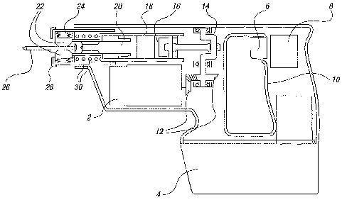
With reference to Figure 1, there is illustrated a power tool in
the form of a nailer device including an electric motor 2
powered by a rechargeable battery pack 4, the power connection
to the motor being selectively controlled by a user operating
actuating means in the form of a trigger 6 connected to a switch
8. The motor 2 and battery 4 are preferably relatively small,
lightweight, and low-powered, akin to those found in cordless
drills and the like. As such, the nailer device is highly portable
and can be supported in one hand by a user via the hand grip 10.
CA 02576345 2007-02-07
WO 2006/008546 PCT/GB2005/002889
The motor 2 rotates cogs 12, which are connected to and rotate
crank shaft 14. The crank shaft 14 moves piston 16 backwards
and forwards along elongate shaft 18 in a reciprocating manner.
The shaft 18 also contains an anvil 20. As the air in the shaft 18
between the anvil 20 and piston 16 is compressed and expanded
by the movement of the piston 16, the anvil 20 is moved
backwards and forwards along elongate shaft 18 in a
reciprocating manner by the same. In a forwards movement the
anvil 20 acts to strike a component, in this example a nail 26,
the head of which is placed in the anterior end of the shaft 18,
with the head being struck upon each forward stroke of the
piston and hence movement of the anvil such that the nail 26 is
inserted incrementally into a substrate until the same is fully
inserted. The speed of this action can be controlled, such as by
an external dial (not shown) which can be set to various speed
levels, or by the amount by which the trigger is depressed to
proportionally vary the amount of power supplied to the motor.
Typically the maximum speed of the action is in the region of
4500bpm. As the nail 26 is driven into the substrate by
delivering a number of relatively low-energy impacts, the system
does not require a dangerously high level of releasable energy to
be stored to achieve the insertion of the nail
The nailer device includes clamping means in the form of nail
clamps 22 which are provided with springs 24 such that the
clamps 22 grip the nail 26 placed therebetween. The nail clamps
may be provided with a retractable collar 28 to help hold the
nail in position as the same is inserted into the substrate. The
nail clamps 22 and/or collar 28 may be adjustably secured to the
nailer device at securing points 30 such that nails are inserted to
a user-specified depth. The nails can be allowed to protrude, be
flush, or even be recessed into the surface in this way.
CA 02576345 2007-02-07
WO 2006/008546 PCT/GB2005/002889
11
The nail clamps 22 and/or collar 28 can also be removed from
the nailer device and retrofitted to an alternative reciprocal
action device, such as a hammer drill, such that the same can be
adapted to the purpose hereinbefore described.
In use, a user places a nail 26 between the nail clamps 22 such
that the head protrudes into the shaft 18. The nailer device is
then positioned such that the nail 26 is adjacent the substrate.
The user then actuates the trigger 6 to engage the motor 2 and
the reciprocating anvil 20. As the user pushes the nailer device
towards the substrate, the head of the nail 26 is struck
repeatedly by the anvil 20, incrementally inserting the nail 26
into the substrate as hereinbefore described. The speed of the
striking action can be increased by increasing the pressure on
the trigger 6. A cartridge of nails may also be fitted to the nailer
device so that successive nails are automatically placed between
the nail clamps 22 as a user releases the previously inserted nail
26.
With reference to Figures 2-3, there is illustrated a second
embodiment of the nailer device power tool including an electric
motor 102 which rotates crank shaft 114 via bearing 132. The
crank shaft 114 is connected to piston 116 via connecting rod
146 and piston pin 148, and moves piston 116 backwards and
forwards along elongate shaft 118 in a reciprocating manner.
The piston pin 148 and connecting rod 146 are threadedly
engaged to allow adjustment of the relative position of the same.
The shaft 118 also contains a hammer 134 and an anvil 120. The
piston 116 is provided with an open ended tubular structure,
concentric with the elongate shaft 118, in which at least part of
the hammer 134 is situated. As the air in the shaft 118 between
the opposing faces of the hammer 134 and piston 116 is
compressed and expanded by the movement of the piston 116,
the hammer 134 is moved backwards and forwards within the
CA 02576345 2007-02-07
WO 2006/008546 PCT/GB2005/002889
12
tubular structure and along the elongate shaft 118 in a
reciprocating manner by the same. The hammer 134 fits tightly
inside the piston 116, while still allowing the reciprocal
movement, such that movement of the hammer 134 is dampened
as the piston 116 moves back and forth. Effectively the inertia
of the hammer 134 is increased. In this embodiment the part of
the hammer 134 is retained within the tubular structure. The
dampened movement allows the hammer to engage the anvil 120
in a smoother action and reduces stress on the device.
In a forwards movement the hammer 134 strikes the anvil 120,
which in turn acts to strike a component such as a nail 126, the
head of which is placed in the anterior end of the shaft 118,
with the head being struck multiple times by the anvil 120 upon
each forward stroke of the piston 116 such that the nail 126 is
inserted incrementally into a substrate until the same is fully
inserted. The anvil is provided with a pin 154 to prevent it from
being accidentally removed from the elongate shaft 118.
The nail 126 or other component is held in the shaft by a head
assembly comprising a body portion 136 and clamping means in
the form of jaws 122, 122' mounted therein, the assembly being
slidably mounted on the elongate shaft 118. The anvil 120 passes
through the end of the elongate shaft 118 in the body portion,
and can extend through the jaws 122, 122'. The elongate shaft
118 in this example does not extend into the head assembly to
be gripped by the jaws 122, 122', such that the jaws 122, 122' do
not have to move apart so far to allow the anvil 120 to pass
therethrough as if the elongate shaft 118 also passed
therethrough. The body portion 136 includes angled edges 138,
138' which engage the adjacent angled edges of jaws 122, 122'
such that as the jaws move away from the distal end of the
elongate shaft 118, they are moved closer together by the angled
edges 138, 138'. As the jaws 122, 122' are adjustable, a range of
CA 02576345 2007-02-07
WO 2006/008546 PCT/GB2005/002889
13
different sized nails or other components can be held
individually by the same.
First biasing means are provided in the form of a spring 140 to
bias the body portion 136 towards the component locating distal
end of the elongate shaft 118. Second biasing means are
provided in the form of a spring 142 to bias the jaws 122, 122'
towards the distal end of the elongate shaft 118, thereby biasing
the jaws 122, 122' to a closed position. Third biasing means are
provided in the form of springs 124 on the body portion 136 to
bias the jaws 122, 122' to an open position, and are less
powerful than the first and second biasing means 140, 142 such
that an external force must be provided by a user to open the
jaws 122, 122'.
This external force can be provided via actuating means in the
form of a trigger 144, which is connected via a frame member
152 to a sleeve 150 housing the spring 140 and the body portion
136. As the trigger 144 is actuated, the body is moved away from
the distal end of the elongate shaft 118, allowing the jaws 122,
122' to be biased towards the open position, and with further
actuation the rest of the head assembly is moved away from the
distal end of the elongate shaft 118, allowing the anvil 120 to
move further along the elongate shaft 118, through the jaws 122,
122', to strike the nail 126 further into the substrate.
An adjustable switch 156 with notches is provided so that the
jaws 122, 122' can be set to different nail shank depths by
rotating the switch 156 around the elongate shaft 118 so that the
protrusion 158 fits into different notches. Thus the nailer device
can be adjusted to move nails 126 into a substrate to a specified
depth.
CA 02576345 2007-02-07
WO 2006/008546 PCT/GB2005/002889
14
Distance members 138 are mounted in the head assembly
adjacent the jaws 122, 122' and are connected to the jaws having
angled edges such that as the jaws 122, 122' are moved away
from the distal end of the elongate shaft 118, as the distance
members 138 engage the substrate, the springs 124 bias the jaws
122, 122' to an open position. This allows the nail 126 to be
partially moved into the substrate before being released to allow
the nail 126 to be moved all the way into the substrate by action
of the anvil 120 moving out of the elongate shaft 118 between
the jaws 122, 122'.
With reference to Figures 4-5, the jaws 122, 122' of the second
embodiment of the invention are shown in more detail. It can be
seen that the jaws 122, 122' interlock, gripping the nail 126
between adjacent V-shaped portions 160, 160' to ensure a tight
hold on the shank. As the head of the nail cannot pass through
in this position, as the nail is moved into the substrate and thus
held by the substrate, the jaws open to allow the head to pass
therethrough for release of the nail, and/or the anvil 120 to pass
therethrough to continue striking the nail 126 close to the
substrate to move the nail completely into the substrate.
In use, a user actuates the trigger 144 to open the jaws 122, 122'
and places a nail 126 between the jaws such that the head of the
nail protrudes into the shaft 18. The nailer device is positioned
such the nail 126 is adjacent the substrate. The user then
engages the motor 102 and the reciprocating anvil 120. As the
user pushes the nailer device towards the substrate, the head of
the nail 126 is struck repeatedly by the anvil 120, incrementally
inserting the nail 126 into the substrate as hereinbefore
described. The nail 126 is thus safely gripped by the jaws 122,
122' until the nail 126 is at least partly embedded into the
substrate, and the user exerts additional force against the
substrate. Thus, in contrast to conventional nail guns, there is
CA 02576345 2007-02-07
WO 2006/008546 PCT/GB2005/002889
no danger of the nail being 'shot' from the device if the user
points the device away from the substrate.
With reference to Figure 6 there is illustrated a variant of the
clamping means, wherein the angled edges 138, 138' of the body
portion 136 are provided with protrusions 162, 162' which
engage the adjacent angled edges of jaws 122, 122' via recessed
guides 164'. In this example the protrusions and guides slot
together in a dovetail fashion, allowing the jaws to slide along
the guides. As the jaws 122, 122' are slidably mounted on the
guides 164, there is no requirement for springs 124 as indicated
by Figures 2-3 to bias the jaws 122, 122' to an open position,
thereby simplifying the mechanism.
Referring to Figure 7 there is shown a variant in the actuating
means as a trigger 166, which is pushed in a see-saw fashion,
rather than pulled, to move the body 136 away from the distal
end of the elongate shaft 118, opening the jaws 122, 122' and
moving the rest of the head assembly from the distal end of the
elongate shaft 118 as hereinbefore described.
It will be appreciated by persons skilled in the art that the
present invention also includes further additional modifications
made to the device which does not effect the overall functioning
of the device.