Note: Descriptions are shown in the official language in which they were submitted.
CA 02576496 2007-01-25
RELOADABLE SUBSONIC RIFLE CARTRIDGE
This invention relates to a reloadable rifle cartridge case that is able to
propel any standard rifle
bullet for a particular caliber at subsonic speeds during free flight at less
than the speed of sound.
BACKGROUND OF INVENTION
Under most normal conditions all rifle cartridges have been designed to propel
a projectile or bullet
from a fired weapon, particularly a rifle, during free flight at speeds
exceeding the speed of sound or
supersonic which is greater than approximately 1086 ft/sec. at sea level under
standard conditions of
temperature and pressure. The faster a projectile travels, the flatter is its
trajectory on route to its
target. Also the faster a projectile travels, the more the effects of lateral
wind deflection are reduced,
maintaining greater accuracy to the intended target. Therefore, to obtain long
range accuracy, it has
been the common practice to load rifle cases with the maximum amount of
propellant within
permissible pressure limits to safely fire the projectile.
When a projectile travels at supersonic speeds it generates an audible sound
called a sonic boom
during its free flight to the target. This sonic boom can be an undesirable
characteristic of supersonic
projectiles as they announce the location of the weapon, which has fired the
round. During a variety
of hunting situations, keeping the firing location of the rifle hidden is
desirable, as it would also be
during certain Military or Police operations in heavily populated areas.
Customized sound
suppressors fitted onto the muzzle end of the rifle can be utilized to reduce
the sound of the muzzle
blast while firing but they will not circumvent the sound of the supersonic
boom as the projectile
breaks the sound barrier. The only method of reducing the effect of the sonic
boom is to propel the
projectile at subsonic speeds so that during free flight it does not exceed
the speed of sound.
The only method of accomplishing this end result is to reduce the amount of
propellant used within
the case. There have been a wide variety of attempts to accomplish this
process. They have ranged
from utilizing a small amount of fast burning pistol powder as the charge,
which has had some very
dangerous results, to using very slow burning cannon powder which is not
readily available to the
handloader in a wide variety of calibers. There have also been attempts to
reduce the exterior size of
the cases, thus reducing the interior capacity, but is impossible for the
reloader to accomplish.
Additional attempts have been to restrict the available space inside the case
by inserting such things
as, paper discs, foam wadding, and pliable expanding cylinder tubes that take
up excess space. All of
these latter methods have their own inherent problems, but most importantly,
none are available to
the handloader to duplicate.
The proposal is to create a reloadable rifle cartridge case which will look
and perform within the
corresponding rifle action identical to that of any standard commercially
produced rifle cartridge but
have its internal capacity to contain propellant reduced so that the
projectile can be safely fired, and
will travel at subsonic speeds.
Previous attempts to create subsonic rounds have entailed a variety of
manufacturing methods. The
problems encountered in attempting to create a safe subsonic cartridge, have
centered around the
quantity of gunpowder used within the case as compared to the available space
existing within the
case. Under loading a rifle case with insufficient propellant will result in
inadequate pressures being
developed to a seal between the neck of the case and the rifle chamber, thus
allowing the gas
produced by the rapid burning of the propellant to escape around the casing
back into the action,
CA 02576496 2007-01-25
resulting in insufficient pressure to propel the projectile out of the rifle
barrel, creating an extremely
dangerous situation.
Other problems encountered have included the inconsistent burning rate of the
propellant within the
cartridge caused by the movement of the powder within the case as the round is
tipped up or down
during the aiming of the rifle at targets on uneven terrain. This creates
inconsistent pressures, though
adequate to expel the projectile from the rifle barrel, the inconsistent
pressures result in very
inaccurate rounds, and difficulty in hitting the desired target.
It has also been the practice to use fast-burning powders, e.g. pistol powders
to create sufficient
pressures to fire a projectile in a subsonic manner. However these powders
exacerbate the problem
of inconsistent propulsion of a projectile from the weapon by reason of the
rapid build up of
pressure within the case and the rapid fall-off of the pressure once the
projectile leaves the case. As
a consequence, the attempts to manufacture subsonic rifle ammunition utilizing
fast burning pistol
powder, fails to provide the energy needed to operate the bolt in a
semiautomatic or automatic
weapon and/or to lock the bolt in an open position upon the firing of the last
round in the magazine.
There has never been a successful attempt to create user friendly and
reloadable rifle cartridge
specifically designed to restrict the internal capacity of the casing to
contain powder thus resulting in
the subsonic travel of the projectile. Such a case has to be easily reloaded
by the shooter with a
minimal level of expertise and equipment, utilizing only the standard
reloading components of
powder, primer and bullet.
Cited documents: US2006081148 BEAL
US5822904 BEAL
US5492063 DITTRICH
US6283035 OLSON/ADKINS
SUMMARY OF INVENTION
The present invention proposes to create a user friendly reloadable rifle
cartridge which will allow
the use of any standard weight and configuration of rifle projectiles to be
utilized and to fire
consistently from round to round in an accurate and subsonic manner. The
cartridge cases can be
produced in any current rifle caliber and externally will appear identical to
commercially available
ammunition cases as to physical dimensions. Starting with the widest end of
the case, known as the
head which has been machined to allow an edge to be grabbed by the rifle
extraction device, moving
up the case is a tapered cylindrical main body resulting in a reduced
circumference known as a
shoulder, and culminating in the neck of the case at one end. Within the neck
is a cavity of a specific
diameter corresponding to the desired caliber of projectile to be utilized in
conjunction with this
cartridge. As part of the design of the head of the case, a machined section
is created to provide
either a rimmed or rimless head for the case to be extracted from the chamber
of the rifle by the
extraction mechanism. Additionally in the center of the head, a cavity is
machined into it, known as
the primer pocket, designed to facilitate the insertion of an ignition charge
known as the primer.
Within the primer pocket is machined a small hole which extends into the
secondary cavity called a
primer hole designed to allow the ignition charge to burn through into the
secondary chamber and
CA 02576496 2007-01-25
ultimately up into the powder chamber igniting the propellant charge. However,
it is proposed that
the external surface of the cases may be colored in a bright and easily
identifiable manner as to
clearly separate the subsonic rounds from the standard ammunition cases, and
to further facilitate
locating them in the field if dropped inadvertently.
The internal structure of the rifle case is substantially altered from that
which exists in standard
ammunition cases. The interior of the case is designed to produce a powder
chamber of restricted
size, extending from the top of the neck of the case, downward into the main
body of the case. Thus
allowing a substantially smaller amount of propellant to be utilized and yet
still fills the case
adequately to create consistent pressures and continuously accurate fired
rounds. A secondary cavity
is created within the case, from the bottom of the powder chamber towards the
primer pocket at the
head of the round, allowing a de-capping rod to pass through the secondary
chamber and be utilized
to remove the spent primer in preparation for reloading.
The cases will be manufactured from either mild steel, stainless steel, brass,
copper bronze or
aluminum depending upon the desire of the client. Brass, being the most widely
used for reloading,
would be suggested as the prime metal of choice.
An important aspect of the proposed invention is that the powder to be
utilized in the reloadable case
is a relatively slow burning type of rifle powder. This powder provides a
rapid peak in pressure build
up within the case, but contrary to fast burning powders, the pressure build
up produced by the slow
burning powder does not fall off sharply, but rather it platforms, so that
there is sustained pressure
within the chamber to assist in working a rifle action.
CA 02576496 2007-01-25
DETAILED DESCRIPTION OF INVENTION
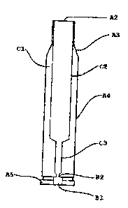
With reference to the accompanying Figures, a vertical representation of the
exterior of the subsonic
cartridge is depicted in FIG. 1 and includes as part of the case an open end
Al, then extending
downward to the neck A2, widening to the shoulder A3, the main body of the
case A4 and
culminating in the head of the case A5 at the bottom. Depicted in FIG 2 is the
representation of the
face of the head section lying horizontally, including A5 being the outer rim
of the head, B1
showing the machined depression in the head called the primer pocket which
will have the primer
inserted, and within the center of the primer pocket is the primer hole B2
through which the ignition
charge from the primer is fired into the main body of the case.
Represented in FIG.3 is the cross section of the interior of the case showing
the powder chamber C2
within which the majority of the propellant is placed. The interior case wall
thickness is indicated as
C1, which serves to restrict the size of the powder chamber. The secondary
chamber is indicated as
C3, which joins the primer pocket to the powder chamber, it also contains
propellant in a loaded
cartridge and provides a guiding cylinder within which the primer de-capping
rod slides into prior to
removing the spent primer. A representation of the cross section of some of
the external case
features are included as A2, the neck, A3 the shoulder, A4 the body and A5 the
head are shown as
well as B 1 the primer pocket and B2 the primer hole.
The representation depicted in FIG. 4 indicates a cross section of a standard
rifle case containing a
subsonic powder charge. This includes a representation of the projectile D1
inserted within the case,
showing the standard case wall thickness as D2. The subsonic powder charge is
indicated as D3 and
the available surplus space within the standard case is indicated as D4. Once
again the primer pocket
of B 1 and the primer hole as B2 are shown to indicate position of primer
charge as it relates to the
propellant charge. The representation depicted in FIG.5 indicates all of the
same features as in FIG.
4 but as the case has been angled upward it shows the relative position of the
propellant charge D3
to the primer pocket B 1. The representation depicted in FIG. 6 indicates the
same case as in FIG. 4
but showing the effects of the angle of the case on the propellant D3 in
relation to the primer pocket
B 1. Both FIG. 5 and FIG. 6 show the inconsistent propellant ignition from
that of FIG. 4 due to the
excess case capacity within the case when reducing the powder capacity to what
would create a
subsonic charge.
Represented in FIG. 7 is a cross section depiction of the subsonic case as in
FIG. 3 but with both a
representation of a projectile inserted in the case neck and the position of
the propellant charge D3
within the case powder pocket C2 and the secondary chamber C3, as it relates
to the position of the
primer pocket B1 and Primer hole B2. What is represented in FIG. 8 is the same
case as in FIG.7 but
now in a horizontal manner showing no propellant movement within the powder
chamber, and
maintaining a constant contact with the primer pocket B1 andd the primer hole
B2. Both FIG.9 and
FIG. 10 indicate the same case as in FIG.7 but shown in an angled up and
angled down position to
demonstrate there is no propellant movement within the powder chamber.
Thus with the reloadable subsonic case design, the resultant primer ignition
charge will contact the
propellant charge in an identical fashion each time it is fired regardless of
the attitude to which the
case is angled. Thus resulting in the consistent performance of the projectile
from round to round,
given identical propellant charges and projectile weights.
The depiction of the item in FIG. 11 and subsequently in 1 l a, 1 lb and l lc
is a representation of the
de-capping rod, designed to be utilized with the subsonic reloadable rifle
case, consisting of a
1
CA 02576496 2007-01-25
threaded striking plate E1, which is threaded onto the threads on the top of
the pin shaft at E2. The
de-capping rod shaft indicated as E3, then reduces in size as indicated in E4
to fit into the secondary
chamber C3. The final extension of the de-capping rod depicted as E5 is the de-
capping pin, used to
fit through the primer hole B2 and remove the spent priuner seated in the
primer pocket B1. The
depiction of three different sizes of de-capping rods as in FIG 11a, 11b and l
lc, is a representation
of the various sizes of the de-capping pin as would be required to insert into
a variety of reloadable
subsonic rifle cases designed in different calibers. The representation in
FIG. 12 indicates the
threaded striking plate El in both a side and face view, also showing the
threaded hole in the niiddle
of the striking plate E6. The diagrams represented in FIG. 13, and
subsequently 13a, 13b and 13c,
indicate a representation of the various sizes and designs of the reloadable
subsonic rifle cases that
will require a correspondingly sized de-capping rod to allow ease of reloading
the subsonic rifle
cartridge case.
DESCRIPTION OF DRAWINGS
FIG. 1 is a schematic representation, showing the exterior of the reloadable
case from a lateral view
of the side.
FIG. 2 is a schematic representation, showing the exterior of the reloadable
case from and end view
of the head.
FIG. 3 is a schematic representation, showing a sectional view of the design
of the interior of the
case depicted in FIG. 1.
FIG. 4 is a schematic representation, showing a sectional view of a standard
rifle cartridge case lying
horizontal containing a subsonic charge of propellant.
FIG. 5 is a schematic representation, showing the sectional view of the case
from FIG. 4 with a
subsonic charge of propellant and elevated in an upward angle to show
propellant movement within
the case.
FIG. 6 is a schematic representation, showing the sectional view of the case
from FIG. 4 with a
subsonic charge of propellant and angled downward to show propellant movement
within the case.
FIG. 7 is a schematic representation, showing the sectional view of the case
from FIG. 1 with a
subsonic charge of propellant.
FIG. 8 is a schematic representation, showing the sectional view of the case
from FIG. 1 with a
subsonic charge of propellant, lying horizontal, and showing no propellant
movement within the
case.
2
CA 02576496 2007-01-25
FIG. 9 is a schematic representation, showing the sectional view of the case
from FIG. 1 with a
subsonic charge of propellant and elevated in an upward angle to show no
propellant movement
within the case.
FIG. 10 is a schematic representation, showing the sectional view of the case
from FIG. 1 with a
subsonic charge of propellant and elevated in a downward angle to show no
propellant movement
within the case.
FIG. 11 (11 a 11 b 11 c) is a schematic representation, showing the design of
the primer de-capping
rod necessary for the reloading of the subsonic cartridge case.
FIG. 12 is a schematic representation, showing the design of the threaded
striking plate which
threads onto the de-capping rods in FIG. 1
FIG. 13 (13a, 13b, 13c) is a schematic representation, showing an example of
the various designs of
the subsonic cartridge cases, requiring a specifically cut de-capping rod to
be manufactured to fit
into the case for reloading.
3