Some of the information on this Web page has been provided by external sources. The Government of Canada is not responsible for the accuracy, reliability or currency of the information supplied by external sources. Users wishing to rely upon this information should consult directly with the source of the information. Content provided by external sources is not subject to official languages, privacy and accessibility requirements.
Any discrepancies in the text and image of the Claims and Abstract are due to differing posting times. Text of the Claims and Abstract are posted:
| (12) Patent: | (11) CA 2576541 |
|---|---|
| (54) English Title: | APPARATUS AND METHOD FOR LEVITATION OF AN AMOUNT OF CONDUCTIVE MATERIAL |
| (54) French Title: | APPAREIL ET PROCEDE POUR LA LEVITATION D'UNE CERTAINE QUANTITE DE MATERIAU CONDUCTEUR |
| Status: | Expired and beyond the Period of Reversal |
| (51) International Patent Classification (IPC): |
|
|---|---|
| (72) Inventors : |
|
| (73) Owners : |
|
| (71) Applicants : |
|
| (74) Agent: | SMART & BIGGAR LP |
| (74) Associate agent: | |
| (45) Issued: | 2012-01-10 |
| (86) PCT Filing Date: | 2005-05-31 |
| (87) Open to Public Inspection: | 2006-03-02 |
| Examination requested: | 2007-02-09 |
| Availability of licence: | N/A |
| Dedicated to the Public: | N/A |
| (25) Language of filing: | English |
| Patent Cooperation Treaty (PCT): | Yes |
|---|---|
| (86) PCT Filing Number: | PCT/EP2005/005905 |
| (87) International Publication Number: | EP2005005905 |
| (85) National Entry: | 2007-02-09 |
| (30) Application Priority Data: | ||||||
|---|---|---|---|---|---|---|
|
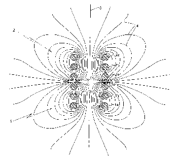
The invention relates to an apparatus for levitation of an amount of
conductive material, comprising a coil for keeping the material in levitation
using a varying electric current in the coil. According to the invention, the
apparatus comprises two coils, a first coil and a second coil, both coils
generating an alternating electromagnetic field during use, the alternating
electric field of the first and the second coil counteracting each other,
wherein the first and second coil are positioned such that the conductive
material that is kept in levitation between the first coil and the second coil
is evaporated. The invention also relates to a method for generating an amount
of levitated conductive material.
L'invention concerne un appareil pour la lévitation d~une certaine quantité de matériau conducteur, comprenant une bobine pour conserver le matériau en lévitation en utilisant un courant électrique variant dans la bobine. Selon l~invention, l~appareil comprend deux bobines, une première bobine et une deuxième bobine, les deux bobines générant un champ électromagnétique alternatif pendant l~utilisation, les champs électriques alternatifs de la première et de la deuxième bobine étant antagonistes l~un par rapport à l~autre, lesdites première et deuxième bobines étant positionnées de telle manière que le matériau conducteur qui est conservé en lévitation entre la première bobine et la deuxième bobine s~évapore. L~invention concerne également un procédé pour générer une quantité de matériau conducteur en lévitation.
Note: Claims are shown in the official language in which they were submitted.
Note: Descriptions are shown in the official language in which they were submitted.
2024-08-01:As part of the Next Generation Patents (NGP) transition, the Canadian Patents Database (CPD) now contains a more detailed Event History, which replicates the Event Log of our new back-office solution.
Please note that "Inactive:" events refers to events no longer in use in our new back-office solution.
For a clearer understanding of the status of the application/patent presented on this page, the site Disclaimer , as well as the definitions for Patent , Event History , Maintenance Fee and Payment History should be consulted.
| Description | Date |
|---|---|
| Time Limit for Reversal Expired | 2016-05-31 |
| Letter Sent | 2015-06-01 |
| Grant by Issuance | 2012-01-10 |
| Inactive: Cover page published | 2012-01-09 |
| Inactive: Final fee received | 2011-10-28 |
| Pre-grant | 2011-10-28 |
| Notice of Allowance is Issued | 2011-06-03 |
| Letter Sent | 2011-06-03 |
| 4 | 2011-06-03 |
| Notice of Allowance is Issued | 2011-06-03 |
| Inactive: Approved for allowance (AFA) | 2011-06-01 |
| Letter Sent | 2011-01-26 |
| Inactive: Multiple transfers | 2011-01-06 |
| Amendment Received - Voluntary Amendment | 2010-11-05 |
| Inactive: S.30(2) Rules - Examiner requisition | 2010-06-30 |
| Inactive: IPRP received | 2008-02-20 |
| Letter Sent | 2007-06-05 |
| Inactive: Correspondence - Formalities | 2007-05-01 |
| Inactive: Single transfer | 2007-05-01 |
| Inactive: Cover page published | 2007-04-25 |
| Inactive: Courtesy letter - Evidence | 2007-04-17 |
| Inactive: Acknowledgment of national entry - RFE | 2007-04-11 |
| Letter Sent | 2007-04-11 |
| Application Received - PCT | 2007-03-02 |
| National Entry Requirements Determined Compliant | 2007-02-09 |
| Request for Examination Requirements Determined Compliant | 2007-02-09 |
| All Requirements for Examination Determined Compliant | 2007-02-09 |
| Application Published (Open to Public Inspection) | 2006-03-02 |
There is no abandonment history.
The last payment was received on 2011-05-10
Note : If the full payment has not been received on or before the date indicated, a further fee may be required which may be one of the following
Patent fees are adjusted on the 1st of January every year. The amounts above are the current amounts if received by December 31 of the current year.
Please refer to the CIPO
Patent Fees
web page to see all current fee amounts.
| Fee Type | Anniversary Year | Due Date | Paid Date |
|---|---|---|---|
| Basic national fee - standard | 2007-02-09 | ||
| Request for examination - standard | 2007-02-09 | ||
| MF (application, 2nd anniv.) - standard | 02 | 2007-05-31 | 2007-04-16 |
| Registration of a document | 2007-05-01 | ||
| MF (application, 3rd anniv.) - standard | 03 | 2008-06-02 | 2008-05-01 |
| MF (application, 4th anniv.) - standard | 04 | 2009-06-01 | 2009-05-01 |
| MF (application, 5th anniv.) - standard | 05 | 2010-05-31 | 2010-05-03 |
| Registration of a document | 2011-01-06 | ||
| MF (application, 6th anniv.) - standard | 06 | 2011-05-31 | 2011-05-10 |
| Final fee - standard | 2011-10-28 | ||
| MF (patent, 7th anniv.) - standard | 2012-05-31 | 2012-04-30 | |
| MF (patent, 8th anniv.) - standard | 2013-05-31 | 2013-04-30 | |
| MF (patent, 9th anniv.) - standard | 2014-06-02 | 2014-05-27 |
Note: Records showing the ownership history in alphabetical order.
| Current Owners on Record |
|---|
| TATA STEEL NEDERLAND TECHNOLOGY B.V. |
| Past Owners on Record |
|---|
| GERARDUS GLEIJM |
| JANIS PRIEDE |
| JOHANNES ALPHONSUS FRANCISCUS MARIA SCHADE VAN WESTRUM |
| LAURENT CHRISPTOPHE BERNARD BAPTISTE |

