Note: Descriptions are shown in the official language in which they were submitted.
CA 02576543 2007-01-30
PLOW HITCH WITH CAM LOCKING BLOCKS
Background of the Invention
The present invention relates to snow plow hitches, and methods for mounting
and demounting the hitches from vehicles.
U.S. Pat. No. 6,594,924 discloses a snow blade mount and lift assembly for a
vehicle that is easily attachable and removable from the vehicle. The
apparatus
provides a hydraulically operated snow blade and lift assembly for a vehicle
that is
attached and removed from the vehicle using a self-aligning hitch mount devoid
of
conventional mounting pins. The self-alignment feature includes a receiver
plate for
mounting to the vehicle chassis and a one-piece plow assembly and lift frame
readily
removably coupled to the receiver plate. The plow assembly preferably includes
a
blade trip frame and a snow blade removably coupled to the trip frame. This
snow
blade hitch mount also includes a jack for lifting the assembly for proper
vertical
alignment with the vehicle chassis mount receiving plate.
U.S. Pat. Nos. 5,353,530; 6,711,837; 6,928,757; 6,944,978; and Re. 35,700
describe a different way of implementing a snow plow hitch assembly for a
vehicle that
is easily attachable and removable from the vehicle, including an integrated
jack
assembly.
Although the equipment and methods described in these patents represent
improvements relative to previous equipment and methods, especially for use
with
multi-purpose vehicles owned and operated by individuals, such as pick up
trucks,
there is a continuing need for further simplification and ease of use, while
assuring
reliability and durability.
Summary of the Invention
According to one aspect, such further simplification, ease of use,
reliability, and
durability are provided by a plow hitch assembly comprising a substantially
horizontal
hitch frame having a front end effector to mount a plow, a lift frame
pivotally connected
to and extending vertically from the back end of the hitch frame, a back end
effector for
CA 02576543 2007-01-30
mounting to a vehicle, and an actuating system connected between the lift
frame and
the front end effector for raising and lowering the hitch frame and plow
together relative
to the back end effector, wherein the back end effector for mounting to the
vehicle has
an associated latching device and a distinctly actuated device for locking the
latch in
place.
Preferably, the back end effector includes two substantially parallel, spaced
arms extending rearward from the lift frame for mating with respective spaced
guides
on a vehicle mount frame as the vehicle moves toward the back of the hitch
frame, and
two spaced latches for engaging a latch bar on the vehicle mount frame when
the arms
are fully mated with the guides. Each latch is rotatably connected to the lift
frame and
comprises a recess such that in a first rotational position the recess faces
rearward for
receiving the bar as the vehicle guides fully mate with the arms and in a
second
rotational position the recess faces vertical to capture and prevent the bar
from moving
horizontally out of the lift frame. A latch handle extends from at least one
latch, for
rotating the latch between the first and second positions. A stop surface is
situated on
the latch remote from the recess, and a lock block supported by the lift
frame, abuts the
stop surface to prevent rotation of the latch when the latch is in the second
position.
Means are provided for selectively holding the lock block at the stop surface,
and a lock
handle is operatively associated with the lock block, for selectively pulling
the lock block
away from the stop surface. In this manner, the user can operate the lock
handle to
pull the block away from the stop surface, thereby freeing the latch to rotate
from the
second to the first position.
In another aspect, each of the arms is uniformly rectangular in section, with
a
leading end having a pair of vertically oriented rollers at the corners, to
facilitate
insertion into the respective guides. Each guide has a rectangular main
channel
closely conforming in cross section with the arm when the arm is fully
inserted into the
channel and an entry that is larger in cross sectional area than the front of
the arm.
Preferably, the bar passes through the lower portion of the guide, and in the
second
(mounting) position the latch is inside the entry to the guide and the latch
recess faces
downward over the bar.
2
CA 02576543 2007-01-30
In yet another aspect, the hitch assembly having the foregoing mounting
configurations, further includes a jack assembly with a jack tube rotationally
supported
in the hitch frame and a jack leg extending transversely from the jack tube,
rotatable
with the jack tube between a substantially vertical, deployed position and a
non-vertical,
retracted position. An actuator has one end attached to the jack assembly and
another
end forming a handle projecting above the hitch frame, for rotating the jack
assembly.
Means are provided for selectively rotationally securing the jack assembly to
the hitch
frame in the deployed position and the retracted position, as well as
providing a
detached condition in which the jack assembly is rotatable. Means are also
provided
for selectively extending and retracting the leg relative to the tube when the
jack
assembly is in the deployed position.
Another aspect is directed to a method for supporting the foregoing plow hitch
assembly on the ground comprising the steps of (a) lowering the plow to the
ground
while the back end of the hitch assembly is mounted to the vehicle; (b)
rotating the jack
assembly so the jack leg projects substantially vertically toward the ground;
(c)
extending the jack leg to contact the ground; (d) rigidly supporting the
extended jack leg
relative to the frame; (e) moving the lock handle to disengage the block from
the latch
stop surface; and (f) driving the vehicle out of the hitch assembly, whereby
the bar
moves with the vehicle and rides on a cam profile of the recess to rotate the
latch so
the recess opens toward the vehicle, the bar is drawn out of the latch, and
the weight of
the hitch assembly is borne only by the plow and the jack leg.
Another aspect is directed to a method for attaching the foregoing plow hitch
assembly to a vehicle, comprising: (a) pulling the lock block away from the
stop surface
on the latch; (b) rotating the latch handle to point the recess toward the
vehicle; (c)
driving the vehicle toward the back end of the hitch assembly, whereby the bar
moves
with the vehicle and rides on a cam profile of the latch recess to rotate the
latch so the
recess opens substantially vertically to capture the bar and the stop surface
contacts
and receives the lock block; (d) contracting the jack leg off the ground,
whereby the
weight of the hitch assembly is borne substantially only by the plow; and (e)
rotating the
3
CA 02576543 2007-01-30
jack assembly toward the hitch assembly and securing the jack assembly in a
retracted
position.
Other aspects and preferences will be evident from the following detailed
description.
Brief Description of the Drawings
Figure 1 is a schematic representation of the overall context of the present
invention;
Figure 2 is a perspective exploded rear view of the snow blade mounting system
in accordance with a representative embodiment of the present invention;
Figure 3 is a perspective exploded front view of the snow blade mounting
system in the detached condition in accordance with the embodiment of Figure
2.
Figure 4 is a detailed view of the latch and lock of the mounting system in
accordance with a representative embodiment of the present invention;
Figure 5 is a side view of the snow blade assembly corresponding to Figure 3,
shown mounted in the attached condition in accordance with a representative
embodiment of the present invention;
Figure 6 is a plan view of the preferred arms forming one aspect of the back
end
effectors, for entering respective guides on the vehicle mount frame;
Figure 7 is a schematic plan view of a portion of the hitch assembly including
an
integrated jack assembly, with the jack in the retracted position;
Figure 8 is a schematic side view corresponding to Figure 7, with the jack
assembly in the deployed position;
Figure 9 is a schematic view of the jack actuating rod where attached to the
frame.
Figure 10 is a schematic view of the jack actuating rod where attached to the
leg
of the jack;
Figure 11 is a section view of the jackscrew for extending and retracting the
jack
leg;
4
CA 02576543 2007-01-30
Figure 12 is a view of the preferred embodiment, corresponding to and oriented
in the same direction as the view of Figure 3;
Figure 13 is a view of the preferred embodiment, in reverse orientation to the
view of Figure 12;
Figure 14 is a detailed view of the latch and jack of the embodiment shown in
Figure 13, with the jack in the retracted position and the latch in the locked
position;
and
Figure 15 is a detailed view of the latch and jack of Figure 14, with the jack
in the
deployed position.
Detailed Description of the Invention
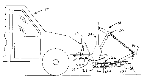
Turning first to Figure 1, there is shown generally at 10 the snow blade hitch
assembly in accordance with a preferred embodiment of the present invention.
The
vehicle 12 has a mount frame 14 attached to the vehicle the chassis (not
shown)
behind the front bumper by any convenient means, such as pins or bolts (not
shown).
The actual design of the interface for attachment to the chassis will depend
upon the
identity (and thus design) of the particular chassis, and is well within the
skill in the art.
The mount frame 14 preferably remains permanently attached to the vehicle
chassis, regardless of whether the snow blade or other accessories are in use.
It is
fixed and has no moving parts; its main purpose is to provide a means of
attachment of
the removable hitch assembly that provides the lift and angle of the snow
blade 16, and
to absorb and transfer any shock loads imposed on the snow blade (or other
accessory) into the vehicle chassis.
In general, the hitch assembly 10 has a substantially horizontal hitch frame
22
supporting front end effector 18 for plow 16. A lift frame 24 is pivotally
connected at 26
to and extends vertically from the back end of the hitch frame. The lift frame
is rigidly
connected to and preferably integral with the back end effector 28 which
selectively
engages the vehicle mount frame 14. When the hitch assembly 10 is connected to
the
vehicle 12, the lift frame is essentially fixed with respect to the vehicle,
through the rigid
5
CA 02576543 2007-01-30
relation to the back end effector 28 and the rigid connection between the back
end
effector 28 and the mount frame 14.
A first plow control system 30 is connected between the lift frame 24 and the
front end effector 18 for raising and lowering the hitch frame 22 and plow 16
together
relative to the pivot axis 26. A second plow control system 20 is connected
between
the hitch frame 22 and the plow blade 16, for changing the angle of the blade
laterally.
Further blade control may also be provided, but is not relevant to the present
invention.
With particular reference also to Figures 2-5, the mount frame 14 is
configured
as two guides and a latch bar 66, for receiving and securing mating structure
on the
back end effector 28. A pair of spaced side guides 32, 34 extend forward and
can be
rectangular as shown in Figure 2 or they can have a tapered profile such that
the
distance between them decreases in the direction towards the vehicle rear. The
height
of each side guide 32, 34 can also taper such that it is progressively lower
in the
direction towards the vehicle rear. These guides can angle in and up, creating
a
trapezoidal wedge in both planes to provide a positive guide to the matching
arms 36,
38 of the back end effector 28.
Preferably, as shown in Figure 3 and Figure 613, the main channels within the
guides 74, 98 are rectangular and horizontal, but the entry 76 for each
channel has
guide surfaces that angle inwardly. In the illustrated embodiment, the latch
bar 66 is
below the guide channel in which the arms 36 and 38 are received. The details
of this
embodiment will be discussed further below.
The lift frame 24 as shown has a generally rectangular shape, although the
present invention is not to be so limited. A transverse vertical actuator
support tube 40
is coupled to the frame 24 between side gusset plates 42, 44 and includes a
central
bracket 46 for attachment of one end of a vertical lifting means 48 such as a
hydraulically driven actuator or cylinder. The opposite end of the vertical
lifting means
48 is coupled to pivot hood 50, which in turn is pivotally mounted to the top
cross bar
52 of the lift frame. The pivot hood has means to which one operative end of a
linking
means such as a chain 54 or the like can be mounted. The other operative end
of the
linking means is mounted by any suitable means to the angle iron 18' at the
front end
6
CA 02576543 2007-01-30
effector or otherwise angle iron coupled to the snow plow blade. This
configuration
constitutes the first control system 30, whereby actuation of the vertical
lifting means 48
causes a corresponding vertical lift of the hood 50, which thereby lifts the
snow plow
blade. Side gussets 42, 44 are shown coupled to vertical legs of the lift
frame 24, such
as by welding, thereby rigidly connecting the back end effectors 28 to the
lift frame 24.
The hitch frame 22 is preferably an A frame structure in which the apex is at
the
front. This results in an intermediate region having laterally spaced apart
beams 56,
58. A trip frame assembly 60 is the preferred means for attaching the snow
blade to
the A-frame. The trip frame 60 allows the blade to pivot forward, which allows
it to trip
over obstacles and absorb shock that would otherwise be transferred into the
plow
frame assembly and vehicle, which in extreme cases would cause substantial
damage.
The trip frame assembly is not required; the snow blade can articulate
directly from the
A-frame by directly coupling thereto via pistons and pivots.
A pair of spaced horizontal actuators such as cylinders 62,64 are each mounted
at one end to the trip frame 60, and the opposite ends of each horizontal
actuator are
pivotally coupled to the base of the A-frame at shoulders or the like (not
shown). These
horizontal actuators are the operative components of the second control system
20 and
are operatively connected to an actuator drive assembly (not shown).
In a conventional manner not shown in the figures, the controls for operating
the
first and second control systems are housed inside the cab of the vehicle for
easy
access to the operator. Typically, there are two separate momentary contact
switches
in any position but the down position, where it is not momentary. A plurality
of
solenoids are used to control the mechanism, such as a solenoid to control the
power
that runs the motor for the pump. This circuit is energized off of any of the
control
positions except the down position, thereby actuating the pump to raise and/or
angle
the blade. Gravity allows the blade to return to ground. Three hydraulic
solenoids are
mounted to the output manifold of the pump. One is the unit that opens the
path to lift
the blade, another is the unit that opens the path to lower the blade
assembly. In the
up position, the first solenoid opens the valve and the pump is energized,
which raises
the blade. In the down position, the other solenoid opens its respective
valve, but the
7
CA 02576543 2007-01-30
pump is not energized, which allows the blade to lower. There is a three-
position
hydraulic spool valve for the angling of the blade. As the switch is pushed to
one side,
it opens the corresponding valve and energizes the pump, which then pumps
fluid into
the corresponding piston which causes the piston to extend and to thereby
angle the
blade. At the same time, it allows the non-pressurized piston to collapse and
fluid to
return to the tank (the force of the extending piston collapses the opposite
piston).
When the switch is engaged in the other direction, the reverse occurs. When
the
switch is returned to the neutral position, so does the valve.
Further details will now be provided regarding the connection of the hitch
assembly 10 to the mount frame 14. The front end of the mount frame includes a
single or segmented round bar 66, of a known diameter. The bar 66 extends
horizontally a distance sufficient to be engaged at or near its opposite ends
by a pair of
opposite latch hooks 68, 70. The spacing between the guide members 32, 34 is
configured to accommodate the arms 36, 38 of the hitch assembly. Each of the
arms
36, 38 is preferably uniformly rectangular in section, and extends in
straight, parallel
relation to the other arm. Each leading end, shown in Figure 6, preferably has
a pair of
vertically oriented rollers 72 at the corners, to facilitate insertion into
the respective
guides 32, 34. Whereas the guides 32, 34 may be trapezoidal, the arms need not
match the taper and thus need not fit snugly within the guides, even when
fully
inserted. The guide members 32, 34 act as a track for receiving and aligning
the arms
36, 38, but the arms can have some play when fully inserted.
As shown in Figures 3, 4, 5 and 6, the preferred relationship between each arm
such as 36 and 38, with the respective guides 74, 98, will be explained in
detail with
respect to guide 74 with the understanding that the guide 98 is symmetric. The
guide
74 has an entry or mouth 76 which is considerably larger in cross sectional
area than
the front of the arm 38 to be received therein. However, when the arm 38 is
fully
inserted into the rectangular channel 78, there is a close relationship
between the
rectangular envelope in the main channel portion 78 and the rectangular
perimeter of
the arm 38. The mouth 76 is bounded on the left by a panel 80 oriented
parallel to the
direction of the arm insertion and through which the latch bar 66 penetrates
at 90. An
8
CA 02576543 2007-01-30
angle plate 82 extends obliquely to the line of entry of arm 38 from plate 80
to the
forward portion of side main side panel 84. Main sides panels 84 and 86 are
parallel to
the line of entry. The front portion of panel 86 has an outwardly directed
panel portion
88 through which the bar 66 passes, and together with panel 80 provide a
relatively
large mouth 76 for initial entry of the arm 38 before being guided into the
main channel
78. The rollers 72 at the front end of the arm prevent hanging up and minimize
the
friction during entry.
It can be appreciated that once the arm 38 is fully received within the main
channel 78 that portion indicated as 104 of the bar will lie between the arm
38 and the
panel 80. It is in this region at 94 where the latch 70 will engage the bar
66, and
together with the closely conforming relation between the front portion of the
arm 38
and the main channel 78, for the pair of guides 74, 98 and latches 70, 68,
produces an
overall rigid engagement between the hitch assembly 10 and the mounting
assembly
14. Preferably, the channels 78 are open at the bottom with only the latch bar
66 and
another bar 102 spanning the main channels, providing the lower contact
surface for
the arms. As shown in Figure 3, the top surface 100 of the guide can be solid
and the
front portion can have an angle plate 96 that also can direct a slightly
misaligned arm
38 toward the main channel 78. As represented in Figures 1 and 5, when the
front end
effectors 28 of the hitch frame 22 are secured to the mounting assembly 14,
arm 38 is
inserted within the main channel 78 of guide 74, arm 36 is fully inserted
within the main
channel of the other guide 98, the latch 70 is secured at 94 on bar 66, and
the latch 68
is secured on bar 66 at 106.
As also shown in Figures 2-5, pivotally coupled to each side gusset 42, 44 via
pivot shaft 108 are respective vertically oriented latched plates 110, 112.
Preferably
the latch plates share a common pivot shaft 114, so that movement of the two
latches
is coordinated. Actuation of one latch results in a corresponding movement of
the other
latch. In this way, the movement of the latches can be controlled by a single
lever 116
coupled to one of the latch plates 110. Alternatively, separate pivot pins
could be used
for each latch plate, with each latch having separate means for actuation.
9
CA 02576543 2007-01-30
Each latch plate 110, 112 has a hook 68, 70 including an arcuate recess
defining cam profile 118 corresponding in angle to the circumference of the
bar 66.
The recess is located on the plate such that in a first rotational position of
the plate
(Figures 2 and 3), the recess faces rearward, for receiving the bar 66 as the
vehicle
guides 32, 34 or 74, 98 fully mate with the arms 36, 38. In a second
rotational position
(Figures 4 and 5) the recess faces vertical to capture and prevent the bar 66
from
moving horizontally or vertically relative to the lift frame 22.
In use for plowing, however, it is desirable that the latches 68, 70 per
Figures 4
and 5 be locked to prevent inadvertent disengagement. For this purpose, a
notch 120
is formed on a latch plate 110, preferably facing forward. A displaceable lock
block 122
is supported by the lift frame 24, and biased with a nose portion into
engagement with
the notch to prevent rotation of the latch. The block 122 can have one end 124
pivotally mounted 126 in spaced relation to the notch, with a handle 128
accessible
from the central region of the A frame, to pivot the block out of the notch
against the
bias of a spring 130 that extends from the gusset 42 or the like, to the
handle 128. The
spring biases the handle 128 clockwise in Figures 4, and the block 122 to the
left,
toward to the notch. Thus, the lock handle 128 is operatively associated with
the lock
block 122, for selectively pulling the lock block out of the notch 120. In
this manner, an
operator can stand over the central region of the hitch frame 22, facing the
arms 36, 38
that guide the hitch assembly 10 relative to the mount frame on the vehicle,
operate the
lock handle 128 to pull the block 122 out of the notch 120, and operate the
latch handle
116 to rotate the latches into a first position with the recess 118 facing
horizontally for
receiving the bar 66.
The recess 118 has a specially contoured shape, which defines a cam profile
that interacts in a planned manner with the known circumference of the bar 66.
When
the hitch assembly 10 is to be detached from the vehicle, the operator unlocks
the lock
block 122 and need not positively unlatch the latch plates 110, 112. Instead,
the
backing up of the vehicle causes the bar 66 to ride on the cam profile 118,
thereby
rotating the latch plates until the recess faces the vehicle and the bar
completely
disengages. Once removed from the notch 120, the lock block 122 rides smoothly
on
CA 02576543 2007-01-30
the outer surface of the latch plate 110. When the hitch assembly is to be
attached to
the vehicle, the recess 118 may already be facing forward (as it was when the
hitch
assembly was detached from the vehicle), so the vehicle merely moves the bar
66 onto
the approach region 118' of the cam profile 118, which produces a moment that
rotates
the latch plate as the bar moves farther into the recess until a second, fully
latched
position is reached. Due to the bias on the lock block 122, it automatically
enters the
notch 120, thereby locking the latch. Of course, the latch handle 116 and the
lock
handle 128 can optionally be used.
The jack assembly 200 of the present invention is shown in Figures 1, 2, 3,
and
7-11. The jack is entirely manually operated, but in a simple, reliable, and
safe
manner. The jack assembly 200 includes a jack tube 202 horizontally spanning
and
rotationally supported in the intermediate region of the hitch frame, e.g.,
between side
beams 56, 58. A jack leg 204 extends transversely from the jack tube 202,
rotatable
212 with the jack tube between a substantially vertical, deployed position and
a non-
vertical, retracted position. An actuator, such a rod 210, has one end 222
attached to
the jack assembly and another end 220 forming a handle projecting above the
hitch
frame 58, for rotating the jack assembly. Means 208, 216 are provided for
selectively
rotationally securing or releasing the jack assembly relative to the hitch
frame in (a) the
deployed position 206' in Figure 8, (b) a detached condition in which the jack
assembly
is rotatable, and (c) the retracted position 206 in Figure 8. The leg 204 and
tube 202
are operatively related such that the leg can be extended 206 relative to the
tube when
the jack assembly is in the deployed position (206" in Figure 8). The actuator
is a rigid
rod slidable obliquely between the beams, having one end attached to the jack
assembly and another end forming said handle.
Preferably, the actuator rod 210 is situated adjacent the apex 132 of the A-
frame
and the jack leg 204 in the retracted position fits within the converging
sides 56", 58"of
the A-frame. The rigid rod passes through a cleat 208 on the hitch frame, and
defines
one of many equivalent means for selectively rotationally securing the jack
assembly in
either of the retracted or deployed positions. For example, the cleat can have
a pair of
11
CA 02576543 2007-01-30
opposed holes for mating with holes on the rod, such that a pin 216 can be
passed
through a selected hole 218, 228 in on the rod.
The leg 204 is preferable extended or retracted by a jack screw or similar
mechanism interposed between the tube 202 and a lift plafform 206 or similar
mechanism within leg 204. A socket 228 at one end of the tube 202, is
operatively
connected to the jack screw, for receiving a crank 214 to selectively expand
or contract
the lift platform and thereby adjust the length of the extension 206 of the
leg from the
tube. In Figure 11, the cover for the jack screw gearing has been omitted to
reveal
orthogonal mating gears 222 and 224. Gear 224 rotates a worm gear or the like
(not
shown) operatively coupling the lift plafform 206 to the leg 204 in any manner
that
would be well within the skill of an ordinary mechanic, for vertical extension
or
retraction. Thus, the crank rotates first gear 222 on a first shaft in tube
202 about a
first, horizontal axis; the first gear 222 rotates mating second gear 224 on a
second
shaft in leg 204 about a second, perpendicular (e.g., vertical) axis; and the
second
shaft is operatively coupled to the pedestal 206 for linear movement within
leg 204
along the second axis.
Thus, the integrated jack assembly 200 is operable according to a method for
supporting a plow hitch assembly 10 on the ground, by lowering the plow 16 to
the
ground while the back end 28 is mounted to the vehicle, rotating the jack
assembly 200
so a jack leg 206 of the jack assembly projects substantially vertically
toward the
ground, extending the jack leg 206 to contact the ground, rigidly supporting
the
extended jack leg relative to the frame 22, demounting the hitch frame 22 from
the
vehicle, and driving the vehicle out of the hitch frame, whereby the weight of
the hitch
assembly is borne only by the plow 18 and the jack leg 206.
A more specific method according to the invention includes, lowering the plow
16 to the ground while the back end 28 is mounted to the vehicle, then
rotating the jack
assembly so a jack leg 206 of the jack assembly projects substantially
vertically toward
the ground. The jack leg is extended to contact the ground, and then fixtured
208, 216
for rigidly supporting the extended jack leg relative to the frame. The
operator then
moves the lock handle 128 to disengage the block 122 from the notch 120. He
then
12
CA 02576543 2007-01-30
drives the vehicle out of the hitch frame 22, whereby the bar 66 moves with
the vehicle
and rides on the cam profile 118 to rotate the latch plate 110 so the recess
opens
toward the vehicle and the bar is drawn out of the latch and the weight of the
hitch
assembly is borne only by the plow and the jack leg.
The steps of attaching a plow hitch assembly 10 to a vehicle, include pulling
the
lock block 122 out of the notch 120, and optionally rotating the latch 116
handle to point
the recess 118 toward the vehicle. If the arms 36, 38 extending from the hitch
assembly 22 are not within the range of capture by the guides 32, 34 or 74, 98
on the
mount frame 14 of the vehicle, the jack can be operated to vertically align
these
structures. The operator drives the vehicle toward the back end 28 of the
hitch
assembly 22, whereby the bar 66 moves with the vehicle and rides on the cam
profile
118 to rotate the latch plate 110 so the recess opens substantially vertically
to capture
the bar, with the notch 120 contacting and receiving the lock block 122. The
jack leg
206 is contracted, off the ground, whereby the weight of the hitch assembly 10
is borne
substantially only by the plow. The jack assembly 200 is rotated toward the
hitch
assembly 22 and secured in the retracted position.
In operation, the vehicle is positioned close to the hitch assembly 22, and
the
jack mechanism 200 is operated so that the lift assembly 24 is raised or
lowered
depending upon the height of the arms. Once the proper height is achieved (as
determined by visual inspection), the vehicle is driven towards the arms. At
this point
the latches 68, 70 are in the unlatched position shown in Figures 2 and 3,
configured to
grasp and engage the bar 66. Once the bar 66 is positioned in the recesses 118
of the
latches, the handle 116 is used to fully draw the latches around the bar and
the latches
are locked by the separate and distinct mechanism 122, as shown in Figures 4
and 5.
The lift assembly is now locked to the vehicle chassis. The jack is then
contracted and
rotated substantially parallel with the A-frame where it is stowed during use
of the plow.
Figures 12-15 show another embodiment of hitch assembly 300 with associated
jack. In the orientation as shown, the front end 302 is connectable to the
plow and the
back end 304 is connectable to the vehicle. The hitch frame 306 is pivotally
connected
to lift frame 308, at 310. The hitch frame is formed by two spaced apart rigid
beams
13
CA 02576543 2007-01-30
= r
312, 314 that converge to an apex 316 at the front and are spanned by a rigid
cross
beam 318 at the back. In an intermediate region between the front and back
ends of
the spaced apart beams, a box frame having generally opposed, rigid walls 320,
322
overlies respective portions of the spaced beams. The box preferably is
directly
supported by the beams, and extends vertically above the beams. A jack tube
324
horizontally spans and is rotationally supported by the box frame walls. A
jack leg 326
extends transversely from the jack tube, rotatable with the jack tube between
a
retracted position substantially between the box frame walls 320, 322 and a
deployed
position substantially vertical below the jack tube. An elongated, rigid
actuator 328 is
slidable obliquely between the box frame walls 320, 322 and between the spaced
beams 312, 314, having one end 330 pivotally attached to the jack leg 326 and
another
end 332 projecting above the box frame walls.
A bracket 334 with associated pins 336, or a clevis, bolt, or other means, is
carried by and preferably rigidly connected to the box frame adjacent the
front end 302
of the hitch frame, with the actuator 328 slidable through or along the
bracket. The
actuator can thus be selectively attached to or otherwise cooperate with the
bracket
334, in (a) a first, retracted holding position, attached intermediate the
ends of the
actuator in which the actuator holds the jack leg in said retracted position
(Figure 14),
(b) a second, detached, actuating position in which the actuator is slidable
between the
box frame walls and between the spaced beams to rotate the tube, and (c) a
third,
deployed holding position attached closer to said other end of the actuator in
which the
actuator holds the jack leg in the deployed position (Figure 15). A jackscrew
336
passes through the jack tube 324 and is operatively connected to a lift
platform 338
extendable within the leg. A socket 340 is present at one end of the tube,
operatively
connected to the jackscrew 336, for cooperating with a crank 342 to
selectively expand
or contract the lift platform and thereby adjust the length of the extension
of the leg
from the tube.
The back end 304 of the hitch assembly 300 is shown in Figures 12 and 13 with
the mounting arms 344, 346 rigidly extending from the lift plafform 308. In
Figures 14
and 15, the arms have been omitted for clarity. The arms are preferably
distinct
14
CA 02576543 2007-01-30
members that are bolted to respective gusset plates 348 or the like which are
in turn
welded or bolted to respective, laterally spaced, vertically extending posts
350. The
preferred form of the arms 344, 346 and the relationship to the mounting frame
on the
vehicle are as described above with respect to Figures 1-6. However, in the
embodiment of Figures 12-15, the latch plate and lock block configuration are
somewhat different.
Each latch plate 352 is pivotally mounted to a respective gusset plate 348,
and
has a cammed recess 354 at one end for engaging the bar of the mounting frame,
as
previously described. The latch handle 356 is attached to the opposite end of
the latch
plate, for implementing or completing the pivoting action. Also at the
opposite end, a
lock stop surface 358 on the plate 352 or handle 354, is preferably oriented
in
substantially the same direction as the handle axis, i.e., preferably
substantially
vertically when the handle and latch plate are in the fully latched position
as shown in
Figures 12-15. This stop surface 358 is analogous to a notch, in that it
defines a sharp
change in direction or discontinuity of the curvature of the edge of the latch
plate,
remote from the recess 354. The important characteristic is that the stop
surface is
shaped and oriented to abut the face 360 of lock block 362 when the plate is
latched to
the mounting frame bar and the lock block is in the lock position shown in
Figures 12-
15.
The lock block 362 can be pivotally mounted at 364 to the gusset plate 352 or
the lift frame cross member 366, to which the gusset plate may be rigidly
attached.
The locking handle 368 is attached to and extends upwardly from the lock
block, and
can pass through a guide or the like 370 attached to post 350, for keeping the
handle
within the bounds of permitted movement. Alternatively, the handle is
pivotally
connected to the guide or the like 370, nearer the end to be grasped.
It can be appreciated that in the limit of the counterclockwise pivoting of
the lock
handle 368 as shown in Figure 13, lock block 362 abuts the latch plate stop
surface
358 and prevents pivoting of the latch plate out of full engagement and
trapping of the
mounting bar. In the limit of clockwise pivoting of the lock handle, the lock
block would
be pulled away from the latch plate 352 and permit counterclockwise pivoting
of the
CA 02576543 2007-01-30
latch handle 356 and latch plate 352, until the latch handle is substantially
horizontal at
9:00 o'clock and the recess 354 is open for receiving or releasing the bar at
3:00
o'clock. To facilitate this extent of pivoting, the latch handle 356 and the
lock handle
368 are offset in the width direction of the hitch assembly.
Means are preferably provided for assuring that the lock block 362 remains in
abutting relation with the stop surface 358 of the latch plate when the latch
plate is in
the latched position (i.e., recess 354 is substantially vertical). The lock
block 362 or
handle 368 is preferably biased, for example by spring 372 acting between the
handle
368 and an anchor 374 on the lift frame.
Another option is a mechanical restraint. For example, in the configuration
shown in Figure 13, the guide 370 can have an open front that is selectively
opened
and closed by a pin and loop 376. When open, the handle can be pulled away
from the
guide, bent slightly to out of alignment with the guide, and have full freedom
to rotate
about pivot 364. After the handle is returned within the guide for locking the
latch plate,
the loop is re-pinned to trap the handle within the guide.
In yet another alternative, pivot 364 is an axle that runs through cross
member
366, to a lock block associated with the other latch plate, for simultaneous
pivoting by a
single lock handle 368. Similarly, one latch handle 356 could be coupled to
the other
latch plate, for simultaneous pivoting. Preferably, the latch handle 356 and
the lock
handle 368 extend side-by-side in the latched and locked condition of the
latch plates,
so that an operator can straddle the hitch assembly on either side of the
beams 312,
314 and easily pivot the lock handle clockwise and the latch handle
counterclockwise
during the process of disengaging the hitch assembly 300 from the vehicle
mounting
assembly.
16