Note: Descriptions are shown in the official language in which they were submitted.
CA 02576683 2007-02-01
162301 RD
AIRCRAFT AUXILIARY GAS TURBINE ENGINE AND METHOD FOR
OPERATING
BACKGROUND OF THE INVENTION
The present invention relates generally to gas turbine engines, and more
particularly
to a non-aircraft-propelling auxiliary gas turbine engine of an aircraft and
to a method
for operating such an engine.
Known auxiliary gas turbine engines are installed in some aircraft to provide
mechanical shaft power to electrical and hydraulic equipment such as
electrical power
generators and alternators and hydraulic pumps. The inlet of the compressor of
such
auxiliary gas turbine engines receives air from the atmosphere. Because the
density
of air decreases with increasing altitude, such auxiliary gas turbine engines,
at
increased altitude, must either work harder to produce a desired shaft power
resulting
in an increased operating temperature or must reduce the output shaft power to
stay
within an operating temperature limit.
Still, scientists and engineers continue to seek improved non-aircraft-
propelling
auxiliary gas turbine engines for aircraft and improved methods for operating
such
engines.
BRIEF DESCRIPTION OF THE INVENTION
A first expression of a first embodiment of the invention is for a non-
aircraft-
propelling auxiliary gas turbine engine installable in an aircraft, wherein
the aircraft
has an aircraft-propelling gas turbine engine and has a cabin adapted to be
pressurized. The auxiliary gas turbine engine includes an auxiliary-gas-
turbine-
engine compressor having an inlet. The inlet is adapted to receive pressurized
air
from the cabin.
A second expression of a first embodiment of the invention is for a non-
aircraft-
propelling auxiliary gas turbine engine of an aircraft, wherein the aircraft
has an
1
CA 02576683 2007-02-01
162301 RD
aircraft-propelling gas turbine engine and has a pressurized cabin. The
auxiliary gas
turbine engine includes an auxiliary-gas-turbine-engine compressor having an
inlet.
The inlet receives pressurized air from the cabin.
A method of the invention is for operating a non-aircraft-propelling auxiliary
gas
turbine engine of an aircraft, wherein the aircraft has an aircraft-propelling
gas turbine
engine and has a cabin adapted to be pressurized. The method includes
providing
pressurized air from the cabin to an inlet of a compressor of the auxiliary
gas turbine
engine. The method includes providing compressed air from the compressor to a
combustor of the auxiliary gas turbine engine. The method includes providing
combustion gases from the combustor to a turbine of the auxiliary gas turbine
engine,
wherein the turbine is mechanically coupled to the compressor.
BRIEF DESCRIPTION OF THE DRAWINGS
The accompanying drawings illustrate an embodiment of the invention wherein:
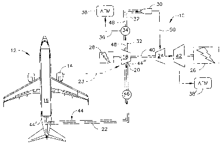
Figure 1 is a schematic representation of an embodiment of an aircraft having
an
aircraft-propelling gas turbine engine and having a non-aircraft-propelling
auxiliary
gas turbine engine connected to two electrical generators.
DETAILED DESCRIPTION OF THE INVENTION
Referring now to the drawings, figure 1 discloses a first embodiment of the
invention.
A first expression of the embodiment of figure 1 is for a non-aircraft-
propelling
auxiliary gas turbine engine 10 installable in an aircraft 12, wherein the
aircraft 12 has
an aircraft-propelling gas turbine engine 14 and has a cabin 16 adapted to be
pressurized. The auxiliary gas turbine engine 10 includes an auxiliary-gas-
turbine-
engine compressor 18 having an inlet 20. The inlet 20 is adapted to receive
pressurized air 22 from the cabin 16. It is noted that an aircraft-propelling
gas turbine
engine of an aircraft is an aircraft gas turbine engine whose main purpose is
aircraft
propulsion and that a non-aircraft-propelling gas turbine engine of an
aircraft is an
aircraft gas turbine engine whose main purpose is not aircraft propulsion.
2
,
CA 02576683 2007-02-01
162301 RD
In a first enablement of the first expression of the embodiment of figure 1,
the inlet 20
of the compressor 18 is adapted to receive bleed air 23 (shown in dashed line)
from
the aircraft-propelling gas turbine engine 14. In one example, such bleed air
23 is
compressed air from a compressor (not shown) of the aircraft-propelling gas
turbine
engine 14. In another example, such bleed air 23 is compressed air from a
bypass
duct (not shown) of the aircraft-propelling gas turbine engine 14. In another
example,
such bleed air is a combination of compressed air from a compressor, and
compressed
air from a bypass duct, of the aircraft-propelling gas turbine engine. Other
examples
are left to the artisan.
In one implementation of the first expression of the embodiment of figure 1,
the
auxiliary gas turbine engine 10 also includes an auxiliary-gas-turbine-engine
turbine
24. The turbine 24 is mechanically coupled to the compressor 18 and is
operatively
connected to an electric power generator 26. In one variation, the auxiliary
gas
turbine engine 10 is also operatively connected to a second electric power
generator
28.
In a first application of the first expression of the embodiment of figure 1,
the
auxiliary gas turbine engine 10 also includes an auxiliary-gas-turbine-engine
combustor 30, wherein the compressor 18 includes an outlet duct 32 in fluid
communication with the combustor 30, and wherein the outlet duct 32 includes a
variable-area bleed valve 34 adapted to release air 36 from the outlet duct 32
to the
atmosphere 38. In a second application, the auxiliary gas turbine engine 10
includes
an auxiliary-gas-turbine-engine combustor 30, wherein the compressor 18
includes an
outlet duct 32 in fluid communication with the combustor 30, and wherein the
outlet
duct 32 is a variable-area outlet duct. In one example of either or both of
these
applications, the variable-area bleed valve and/or the variable-area outlet
duct is
operated to prevent the auxiliary gas turbine engine 10 from stalling (from
back flow
to the cabin) or from surging (from a pressure spike from the cabin), as can
be
appreciated by those skilled in the art.
In a first arrangement of the first expression of the embodiment of figure 1,
the inlet
20 is an acoustically-treated inlet. Acoustic treatment of aircraft components
is well
3
CA 02576683 2007-02-01
162301 RD
known, such as acoustic treatment to reduce noise from aircraft-propelling gas
turbine
engines which reaches passengers within the cabin of the aircraft. Examples of
acoustic treatment of aircraft components are left to the artisan.
In one construction of the first expression of the embodiment of figure 1, the
compressor 18 is a high-pressure compressor supplying compressed air to the
combustor 30, the turbine 24 is a high-pressure turbine mechanically coupled
to the
high-pressure compressor by a shaft 40, and the auxiliary gas turbine engine
10
includes a low-pressure turbine 42 (which, in one example, discharges gas to
the
atmosphere 38') as shown. The operation of such components is well known in
the
art. It is noted that the flow of gas in figure 1 is indicated by arrowed
lines.
In one deployment of the first expression of the embodiment of figure 1,
the auxiliary gas turbine engine 10 includes a connection duct 44. The
connection
duct 44 has an entrance 44' and an exit 44". The entrance 44' is adapted to
receive
pressurized air 22 from the cabin 16. The inlet 20 of the compressor 18 is
adapted to
receive pressurized air 22 from the cabin 16 by being connectable to the exit
44" of
the connection duct 44.
In one extension of the first expression of the embodiment of figure 1, there
is
included a system (not shown) for enhancing the use of cabin air provided to
the inlet
of the compressor of the auxiliary gas turbine engine. The system includes a
system
turbine which has an inlet adapted to receive cabin air and has an outlet in
fluid
communication with the inlet of the compressor of the auxiliary gas turbine
engine.
The system includes a system compressor, mechanically coupled to the system
turbine, which has an inlet adapted to receive air from the atmosphere and
which has
an outlet in fluid communication with the inlet of the compressor of the
auxiliary gas
turbine engine. The atmospheric air is entrained and compressed, wherein the
outlets
of the system turbine and the system compressor have substantially the same
pressure
and are combined to deliver a greater mass flow to the inlet of the compressor
of the
auxiliary gas turbine engine, as can be appreciated by those skilled in the
art. In one
variation, a heat exchanger (not shown) is used to receive waste heat from the
aircraft
4
CA 02576683 2007-02-01
162301 RD
(such as from a cooling system) and to give up heat to the pressurized air
which has
left the cabin but has not yet entered the system compressor.
A second expression of the embodiment of figure 1 is for a non-aircraft-
propelling
auxiliary gas turbine engine 10 of an aircraft 12, wherein the aircraft 12 has
an
aircraft-propelling gas turbine engine 14 and has a pressurized cabin 16. The
auxiliary gas turbine engine 10 includes an auxiliary-gas-turbine-engine
compressor
18 having an inlet 20. The inlet 20 receives pressurized air 22 from the cabin
16. It is
noted that an aircraft-propelling gas turbine engine of an aircraft is an
aircraft gas
turbine engine whose main purpose is aircraft propulsion and that a non-
aircraft-
propelling gas turbine engine of an aircraft is an aircraft gas turbine engine
whose
main purpose is not aircraft propulsion.
In a first enablement of the second expression of the embodiment of figure 1,
the inlet
20 of the compressor 18 receives bleed air 23 (shown in dashed line) from the
aircraft-
propelling gas turbine engine 14. In one example, such bleed air 23 is
compressed air
from a compressor (not shown) of the aircraft-propelling gas turbine engine
14. In
another example, such bleed air 23 is compressed air from a bypass duct (not
shown)
of the aircraft-propelling gas turbine engine 14. In another example, such
bleed air is
a combination of compressed air from a compressor, and compressed air from a
bypass duct, of the aircraft-propelling gas turbine engine. Other examples are
left to
the artisan.
In one implementation of the second expression of the embodiment of figure 1,
the
auxiliary gas turbine engine 10 also includes an auxiliary-gas-turbine-engine
turbine
24. The turbine 24 is mechanically coupled to the compressor 18 and is
operatively
connected to an electric power generator 26. In one variation, the auxiliary
gas
turbine engine 10 is also operatively connected to a second electric power
generator
28.
In a first application of the second expression of the embodiment of figure 1,
the
auxiliary gas turbine engine 10 also includes an auxiliary-gas-turbine-engine
combustor 30, wherein the compressor 18 includes an outlet duct 32 in fluid
CA 02576683 2007-02-01
162301 RD
communication with the combustor 30, and wherein the outlet duct 32 includes a
variable-area bleed valve 34 adapted to release air 36 from the outlet duct 32
to the
atmosphere 38. In a second application, the auxiliary gas turbine engine 10
includes
an auxiliary-gas-turbine-engine combustor 30, wherein the compressor 18
includes an
outlet duct 32 in fluid communication with the combustor 30, and wherein the
outlet
duct 32 is a variable-area outlet duct. In one example of either or both of
these
applications, the variable-area bleed valve and/or the variable-area outlet
duct is
operated to prevent the auxiliary gas turbine engine 10 from stalling (from
back flow
to the cabin) or from surging (from a pressure spike from the cabin), as can
be
appreciated by those skilled in the art.
In a first arrangement of the second expression of the embodiment of figure 1,
the
inlet 20 is an acoustically-treated inlet. Acoustic treatment of aircraft
components is
well known, such as acoustic treatment to reduce noise from aircraft-
propelling gas
turbine engines which reaches passengers within the cabin of the aircraft.
Examples
of acoustic treatment of aircraft components are left to the artisan.
In one construction of the second expression of the embodiment of figure 1,
the
compressor 18 is a high-pressure compressor supplying compressed air to the
combustor 30, the turbine 24 is a high-pressure turbine mechanically coupled
to the
high-pressure compressor by a shaft 40, and the auxiliary gas turbine engine
10
includes a low-pressure turbine 42 (which, in one example, discharges gas to
the
atmosphere 38') as shown. The operation of such components is well known in
the
art. It is noted that the flow of gas in figure 1 is indicated by arrowed
lines.
In one deployment of the second expression of the embodiment of figure 1, the
auxiliary gas turbine engine 10 also includes a connection duct 44 connecting
the inlet
20 to the cabin 16, wherein the inlet 20 receives the pressurized air 22 from
the cabin
16 through the connection duct 44. In one variation, the auxiliary gas turbine
engine
also includes a one-way valve 46 disposed in the connection duct 44. In the
same
or a different variation, the connection duct 44 is acoustically-tuned to
provide at least
some noise isolation between the compressor 18 and the cabin 16.
6
CA 02576683 2013-11-21
162301 RD
A method of the invention is for operating a non-aircraft-propelling auxiliary
gas
turbine engine 10 of an aircraft 12, wherein the aircraft 12 has an aircraft-
propelling
gas turbine engine 14 and has a cabin 16 adapted to be pressurized. The method
includes providing pressurized air 22 from the cabin 16 to an inlet 20 of a
compressor
18 of the auxiliary gas turbine engine 10. The method includes providing
compressed
air 48 from the compressor 18 to a combustor 30 of the auxiliary gas turbine
engine
10. The method includes providing combustion gases 50 from the combustor 30 to
a
turbine 24 of the auxiliary gas turbine engine 10, wherein the turbine 24 is
mechanically coupled to the compressor 18.
In one employment, the method also includes operatively connecting the
auxiliary gas
turbine engine 10 to an electric power generator 26. In the same or a
different
utilization, the method also includes operatively connecting the auxiliary gas
turbine
engine 10 to an alternator (not shown). In the same or a different
utilization, the
method also includes operatively connecting the auxiliary gas turbine engine
10 to a
hydraulic pump (not shown).
In one enactment, the method also includes providing bleed air 23 from the
aircraft-
propelling gas turbine engine 14 to the inlet 20. In one variation of this
enactment,
the method also includes operatively connecting the auxiliary gas turbine
engine 10 to
an electric power generator 26.
In one utilization, the compressor 18 includes an outlet duct 32. The provided
compressed air 48 from the compressor 18 to the combustor 30 is provided
through
the outlet duct 32. The outlet duct 32 is sized to reduce back pressure from
the
compressor 18 to the cabin 16, as can be appreciated by those skilled in the
art.
While there have been described herein what are considered to be preferred and
exemplary embodiments of the present invention, other modifications of these
embodiments falling within the scope of the invention described herein shall
be
apparent to those skilled in the art.
7