Note: Descriptions are shown in the official language in which they were submitted.
CA 02576742 2007-01-31
WO 2006/024148 PCT/CA2005/001310
1
APPARATUS AND METHOD FOR MAKING A SEMI-SOLID METAL SLURRY
TECHNICAL FIELD
The present invention relates to the casting of semi-solid slurries of molten
metal, particularly aluminum and aluminum alloys. More particularly, it
relates to
apparatus for preparing semi-solid slurries and use of a "slurry on demand"
method of preparing such slurries.
BACKGROUND ART
The casting of semi-solid slurries of molten metal has been carried out for
many years. A number of methods for casting such slurries are known in the
art.
These generally involve reheating of previously prepared and conditioned solid
ingots to a semi-solid state then transferring the resulting slurry to a
casting
mould.
However, in recent years a method of casting has been developed
wherein a semi-solid slurry is prepared by controlled cooling of a liquid
alloy in a
crucible. The semi-solid slurry formed on cooling is then transferred from the
crucible to a casting machine and cast without the need for using an
intermediate
solid ingot. This approach has been referred to as "slurry on demand".
US Patent 6,595,266, issued on July 22, 2003 to Orii describes such a
slurry on demand system where a molten alloy is passed over a cooling plate
and
is then collected into a crucible, where it is held in a semi-solid state for
a short
period of time, to allow a preferred particle morphology to develop, and then
cast.
EP Patent Publication No. 0 745 694 (Adachi et al), published April 12,
1996, describes a slurry on demand system where the alloy initial temperature,
grain refiner content and rate of temperature drop within a crucible are
controlled
to develop the desired morphology at which time the slurry is die cast.
US Patent 6,428,636, issued on August 6, 2002 to Doutre et al, describes
a slurry on demand system where the molten alloy is cooled to a predetermined
temperature in the semi-solid range in a crucible of specified thermal mass
and
CA 02576742 2007-01-31
WO 2006/024148 PCT/CA2005/001310
2
temperature, then some of the excess molten alloy is drained prior to
transferring
the semi-solid mass to a casting mould. This latter step causes the semi-solid
mass to become detached from the wall of the crucible making the transfer to
the
casting machine more efficient. In crucibles where such draining is not
provided,
there is often a problem of materials sticking to the crucible walls,
requiring the
use of specific cleaning steps between uses of the crucible. This results in
longer
cycle times required for casting and increases the complexity of the equipment
needed for slurry preparation and casting.
The ability to completely and reliably remove metal from crucibles used to
produce the slurry in slurry on demand processes is an important requirement
to
achieving viability and efficiency. Improvements to metal removal are
beneficial
even in processes in which transfer of the slurry is relatively efficient, as
for
example, in the case of draining or otherwise reducing the adherence of metal
to
the crucible. In such case, it is important that the means for draining the
liquid
phase, also be cleaned and freed of any molten metal that may later solidify
and
cause blockage of the opening.
There is a need therefore for an improved crucible design and method of
use suitable for slurry on demand processing that permits extended repeated
use
between cleaning and/or refurbishment and maintains metal cleanliness
throughout its use.
DISCLOSURE OF THE INVENTION
According to one aspect of the present invention, there is thus provided a
crucible for preparing semi-solid metallic slurry, having a liquid phase and a
solids phase. The crucible comprises a side wall having a lower edge, a
closing
plate engagable against and separable from the lower edge of the side wall and
clamping means for holding the closing plate against the lower edge of the
side
wall.
According to another aspect of the present invention, there is provided a
method of preparing semi-solids slurry, having a liquid phase and a solids
phase.
CA 02576742 2007-01-31
WO 2006/024148 PCT/CA2005/001310
3
The method comprises providing a crucible having a side wall with a lower edge
and a closing plate, holding the closing plate in contact with the lower edge
of the
side wall, filling the crucible with a molten metal, cooling the molten metal
to
produce a semi-solid slurry, releasing the lower edge of the side wall from
contact with the closing plate and finally, transferring the semi-solid slurry
from
the side wall to a casting machine.
BRIEF DESCRIPTION OF THE DRAWINGS
Preferred embodiments of the present invention are described below, in
conjunction with the accompanying figures, wherein:
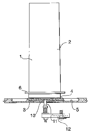
Fig. 1 is a vertical cross-sectional view of an embodiment of the present
invention, illustrating the side wall and closing plate of the crucible;
Fig. 2 is a detail of Fig. 1; showing the hole and plug in a plugged
arrangement;
and
Fig. 3 is a vertical cross-sectional view of the support plate and closing
plate,
showing a preferred means of cleaning the hole.
BEST MODES FOR CARRYING OUT THE INVENTION
With reference to Fig. 1, a crucible I is shown that is designed to receive
molten metal to be cooled into a semi-solid metallic slurry. The crucible I is
formed from a side wall in the form of an open ended tube 2, which rests on a
closing plate 3. Any convenient cross-sectional shape may be used, but a
generally cylindrical shape is particularly preferred. The tube 2 is held in
contact
against the closing plate 3 to form a seal between a lower edge 4 of the tube
2
and a surface of the closing plate 3.
The tube 2 is preferably slightly tapered, more preferably typically with less
than about 5 degrees of taper and most preferably about I degree of taper. The
taper may be in either direction but most preferably having a larger diameter
at
the lower edge 4, which contacts the closing plate 3. The closing plate 3 in
turn
can be mounted on a larger support plate 5 that forms part of a support for
the
CA 02576742 2007-01-31
WO 2006/024148 PCT/CA2005/001310
4
crucible 1. Pressure between the tube 2 and the closing plate 3 can be
maintained by a number of means well known in the art, including the use of a
clamping device 14. Preferably, the clamping device 14 is in the form of a
horseshoe style clamp that is connected to the support plate 5 and which can
be
remotely actuated to rotate onto and clamp down on a flange 6 that runs around
the tube 2, above the lower edge 4. Actuation for the clamp can be pneumatic
or
hydraulic.
The support plate 5 can be remotely controlled to move in a swirling
motion to thereby agitate the crucible and enhance cooling of the molten metal
in
forming the semi-solid slurry.
The closing plate 3 may be manufactured from refractory materials, and
particularly from alumina-silicate refractory boards such as N-17TM refractory
board produced by Pyrotek Inc., or can be a metal, such as steel, stainless
steel
or titanium.
The metal tube 2 may be manufactured from a refractory material or metal
as well, and is preferably made from steel or stainless steel. In a preferred
embodiment, material for the tube 2 and tube thickness and the material and
dimensions of the closing plate 3 are chosen based on predetermined heat
capacity and mass requirements for cooling the molten metal into the desired
semi-solid slurry consistency. However, it is also possible to use a tube and
closing plate with less precisely determined properties, together with an
external
heating or cooling system. Any metallic surfaces of either the closing plate 3
or
the tube 2 are preferably coated with suitable metal resistant coatings. Such
coatings are well known in the art and, in the case of aluminum alloys, can
'25 include mica wash and boron nitride. Any other operable refractory based
coatings and coating methods may be used, including coatings applied as wash
coats, spray coats or coatings applied by plasma spraying.
With reference to Fig. 2, the closing plate 3 and the support plate 5
preferably contain at least one hole 10 running through them. The hole 10 is
preferably tapered, having a smaller diameter adjacent the lower edge 4 of the
CA 02576742 2007-01-31
WO 2006/024148 PCT/CA2005/001310
tube 2 and widening therefrom. The hole 10 has a preferred diameter of from
about 3 to about 5 millimeters. In cases where the hole is tapered, the
smaller
diameter is from about 3 to about 5 millimeters. The particular diameter used
is
dependent on the alloy cast and size of slurry charge to be prepared. The
5 closing plate 3 can preferably have an upwards conical profile, to enhance
draining of liquid metal from the hole 10. A plug 11 fits within the hole 10
from an
underside of the supporting plate 5. The plug 11 is optionally mounted on a
pivoting cantilever arm 12 that allows for manipulation of the plug 11 in and
out of
the hole 10. The pivoting cantilever arm 12 can be remotely actuated to plug
or
unplug the hole 10, and can be either pneumatically or hydraulically actuated.
The plug 11 can be made from any suitable material known in the art to be
resistant to the molten metal, and is preferably made of boron nitride.
In a preferred mode of operation, the tube 2 is first cooled to a
predetermined temperature to aid in cooling the molten metal into a semi-solid
slurry. The tube 2 can be cooled to a temperature ranging from room
temperature up to 100 - 150 C. The plug 11 is inserted in the hole 10 in the
closing plate 3 and the tube 2 is clamped to the closing plate 3 by the
clamping
device 14. Molten metal, typically having a temperature greater than 700 C,
is
poured into the crucible 1, where it is agitated by movement of the support
plate
5 and cools to form a semi-solid slurry. The semi-solid slurry comprises a
liquid
phase and a solids phase. A cooling process such as that taught in US Patent
no. 6,428,636 is particularly preferred for this purpose.
After a pre-determined period of time, which can be while agitation is still
in progress, the plug 11 is removed from the hole 10 by pivoting the pivoting
cantilever arm 12 and some of the liquid phase is allowed to flow out through
the
hole 10. In draining off some of the liquid phase, the fraction of solids
phase in
the slurry is increased, typically, from about 35 - 40wt% to about 45 - 55wt%.
Although a single relatively large hole 10 is preferably used to drain a
portion of the liquid phase, the semi-solid structure and thixotropic
behaviour of
the slurry within the crucible I prevents the solid phase from escaping and
only
CA 02576742 2007-01-31
WO 2006/024148 PCT/CA2005/001310
6
liquid phase is removed. As mentioned before, it is desirable to drain off
some of
the liquid phase so that the semi-solid slurry in the crucible 1 becomes
detached
from the tube 2 of the crucible 1, thereby easing transfer of the slurry to a
casting
machine.
Once some of the liquid phase is drained off, the clamping device 14 is
released from the tube 2 and the tube 2 containing the semi-solid mass is
transferred to a shot sleeve of a conventional die casting machine for forming
and solidifying the slurry. The semi-solid slurry leaves the tube 2 through
its
lower edge 4. The tube can be transferred using any known means in the art,
for
example, using a remotely controlled robot (not shown).
Once the tube 2 has been un-clamped and removed from the support
plate 5, the hole 10 in the closing plate 3 can be cleaned of any molten metal
that
would otherwise build up and obstruct the hole 10. Because there is no filter
element of similar device required in the hole 10, there is little surface
area for
molten metal to accumulate and the removal of any small residue is quickly
accomplished. With reference to Fig. 3, the hole 10 can preferably cleaned by
a
simple burst of compressed from an air jet 8. The hole 10 and the closing
plate 3
are then ready to be clamped to the tube 2 for formation a next batch of semi-
solid slurry. The air jet 8 can optionally be remotely moved into position
under
the hole 10 and can be remotely actuated to deliver a burst of compressed air.
Actuation of the air jet 8 can be pneumatic or hydraulic.
A rotating air jet (not shown) may also preferably be used to blow away
any molten metal droplets that may still adhere to the tube after the semi-
solid
slurry has been transferred to the casting machine.
In this manner, each of the steps for clamping the support plate 5 to the
tube 2, agitating the support plate 5, unclamping the tube 2 from the support
plate 5, transferring the slurry to the casting mould, cleaning the hole 10 in
the
closing plate 3 and re-clamping the tube 2 to the support plate 5 can be
timed,
automated and remotely controlled.
CA 02576742 2007-01-31
WO 2006/024148 PCT/CA2005/001310
7
Because of the particular design features, the crucible 1, in particular
when used in the preferred manner, remains free of significant metal residues
and can be continuously reused without stopping on each casting cycle for
mechanical cleaning and recoating.
This detailed description of the devices and methods of the present
invention is used to illustrate the prime embodiments of the present
invention. It
will be apparent to those skilled in the art that various modifications can be
made
in the present devices and methods and that various alternative embodiments
can be utilized. Therefore, it will be recognized that modifications can be
made in
the present invention without departing from the scope of the invention, which
is
limited only by the appended claims.