Note: Descriptions are shown in the official language in which they were submitted.
CA 02577153 2007-02-14
WO 2006/028866 PCT/US2005/031030
TOOLHOLDER AND Gl'7"i"1TNG INSERT FOR A TOOLHOLDER ASSEMBLY
BACKGROUND OF THE INVENTION
Field of the Invention
[0001] The invention is directed to a metalworking operation and more
particularly to a
toolholder and a mating cutting insert. The subject invention is also directed
to a method of
assembling the toolholder and mating cutting insert to form a toolholder
assembly.
Description of Related Art
[0002] During a metalworking operation, a cutting insert is typically mounted
upon a
toolholder which secures the cutting insert as it is urged against a
workpiece. Typically, the
cutting insert fits into a shaped pocket within the toolholder and is held
within the pocket by
either a hold-down screw or a clamp. However, when the cutting insert is held
within a
pocket, it is important to provide clearance for the cutting edge of the
insert within the pocket
so that it does not become damaged, and furthermore, it is important to
machine the pocket so
that the cutting edge of the insert in contact with the workpiece is properly
located.
[0003] A toolholder and cutting insert for a toolholder assembly are needed
whereby the
cutting insert may be accurately positioned within the toolholder while at the
same time
secured within the toolholder in a relatively simple fashion.
SUMMARY OF THE INVENTION
[0004] One embodiment of the subject invention is directed to a toolholder
adapted to
accept a cutting insert having a tapered shank and a rearwardly facing face
thereon. The
toolholder has a toolholder body, a bore extending rearwardly therein and
having a central
axis extending therethrough, and a forwardly facing surface extending about
the bore for
abutment with the rearwardly facing face of the insert. The bore has a tapered
section
dimensioned to provide a resilient interference fit with the shank when the
forwardly facing
surface is in abutment with the rearwardly facing face and wherein the tapered
section
narrows as the bore extends rearwardly.
[0005] A second embodiment of the invention is directed to a cutting insert
adapted to be
mounted within a toolholder having a bore extending rearwardly therein and a
forwardly
facing surface thereon. The insert comprises a cutting insert body having a
forward end with
a cutting edge thereupon, a shank receivable in the bore and extending
rearwardly from the
forward end, a central axis extending therethrough, and a rearwardly facing
face between the
forward end and the shank of the insert for abutment with the forwardly facing
surface of the
toolholder. The shank has a tapered section dimensioned to provide a resilient
interference fit
-1-
CA 02577153 2007-02-14
WO 2006/028866 PCT/US2005/031030
with the bore when the rearwardly facing face of the insert is in abutment
with the forwardly
facing surface of the toolholder.
[0006] A third embodiment of the subject invention is directed to a toolholder
system
comprising a toolholder and a cutting insert. The toolholder has a body with a
toolholder
bore extending rearwardly therein, a central axis extending therethrough and a
forwardly
facing surface extending about the bore. The cutting insert has a forward end
with a cutting
edge thereupon, an insert shank extending rearwardly from the forward end and
having a
central axis extending therethrough, and a rearwardly facing face. The
forwardly facing
surface of the toolholder is in contact with the rearwardly facing face of the
insert. The
toolholder bore has a tapered section and the shank has a slightly mismatched
taper, wherein
each is dimensioned to provide a resilient interference fit with each other
when the forwardly
facing surface of the toolholder is in abutment with the rearwardly facing
face of the insert.
[0007] A fourth embodiment of the subject invention is directed to a method of
releasably
mounting a cutting insert onto a toolholder having a bore extending rearwardly
therein and a
forwardly facing surface extending about the bore. The insert has a forward
end, a shank
extending rearwardly therefrom, and a rearwardly facing face. The shank has a
taper
narrowing away from the forward end. The method comprises the steps of: a)
inserting the
insert into the toolholder bore, b) resiliently interference fitting the
tapered shank into the
toolholder bore, and c) abutting the rearwardly facing face of the insert
against the forwardly
facing surface of the toolholder.
BRIEF DESCRIPTION OF THE DRAWING(S)
[0008] Fig. 1 is an isometric view of a toolholder assembly wherein a cutting
insert is
mounted within a toolholder;
[0009] Fig. 2 is an exploded section view of an insert positioned relative to
a toolholder;
[0010] Fig. 3 is section view of the insert in Fig. 2 inserted within the
toolholder;
[0011] Fig. 4 is an isometric view showing details of one embodiment of the
subject
invention;
[0012] Fig. 5 is an isometric view of a second embodiment of a toolholder and
cutting
insert;
[0013] Fig. 6 is a side view of the toolholder assembly illustrated in Fig. 5;
[0014] Fig. 7A is a top view of the toolholder bore/insert shank showing an
oval shape;
[0015] Fig. 7B is a top view of the toolholder bore/insert shank showing a
triangular shape;
and
-2-
CA 02577153 2007-02-14
WO 2006/028866 PCT/US2005/031030
[00161 Fig. 7C is a top view of the toolholder bore/insert shank showing a
lobed triangular
shape.
DESCRIPTION OF THE PREFERRED EMBODIMENTS
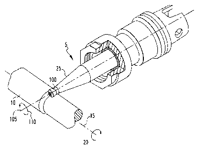
[0017] Fig. 1 illustrates a workpiece 10 rotating about a centerline 15 in a
direction
indicated by arrow 20 when, for example, the workpiece 10 is mounted upon a
lathe. A
toolholder 25 has mounted thereupon a cutting insert 100 to form a toolholder
assembly 5.
The insert 100 mounted upon the toolholder 25 may be rotatable about a central
axis 105
extending through the insert shank (115 in Fig. 2) in a direction indicated by
arrow 110. The
toolholder 25 may also be held securely without rotation. For purposes of the
discussion
herein, the toolholder assembly may be used in either stationary or rotating
applications.
[0018] Additional details of the insert, toolholder and of the support member
for holding
the toolholder may be found in United States Patent Application Number
10/653,712 titled
"Method and Assembly for Rotating a Cutting Insert With Fluid Impingement and
the Insert
Therein" filed September 2, 2003, assigned to the assignee of the present
application and
hereby incorporated by reference.
[0019] Figs. 2 and 3 illustrate cut-away views of the toolholder 25 and the
cutting insert
100 in accordance with the subject invention. For purposes of identification,
the direction
from the bottom to the top of Fig. 2 will be referred to as forward and the
opposite direction
will be referred to as rearward. The toolholder 25 is adapted to accept the
cutting insert 100
having a tapered shank 115 with a central axis 105 extending therethrough and
a rearwardly
facing face 120 thereon. The rearwardly facing face 120 is located between the
forward end
130 of the insert body 125 and the shank 115 of the insert body 125. The
toolholder 25 has a
toolholder body 30 and a bore 35 extending rearwardly therein. The bore 35 has
a central
axis 36 extending therethrough. The toolholder body 30 furthermore has a
forwardly facing
surface 40 extending about the bore 35 for abutment with the rearwardly facing
face 120 of
the insert 100.
[0020] For purposes of discussion, even though the cutting insert shank 115
has a central
axis 105 and the toolholder bore 35 has a central axis 36, when the insert 100
is mounted
within the toolholder 25, these axes 105, 36 are co-axial. Therefore,
throughout the
application reference will be made to a single central axis 105 with the
understanding that it
applies to both axes 105, 36 when the insert 100 and toolholder 25 are
assembled and when
separated, the insert shank 115 and the toolholder bore 35 each have separate
central axes
105, 36, respectively.
-3-
CA 02577153 2007-02-14
WO 2006/028866 PCT/US2005/031030
[0021] The bore 35 has a tapered section 45 to provide a resilient
interference fit with the
shank 115 when the forwardly facing surface 40 is in abutment with the
rearwardly facing
face 120. The tapered section 45 narrows as the bore 35 extends rearwardly. As
illustrated in
Fig. 3 with the insert 100 fully inserted within the bore 35 of the toolholder
body 30 the
rearwardly facing face 120 of the cutting insert 100 abuts the forwardly
facing surface 40 of
the toolholder body 30, while at the same time, the tapered shank 115 of the
cutting insert
body 125 contacts the wa1137 of the bore 35 to provide a resilient
interference fit. As shown
in Fig. 2, the wall 37 of the tapered section 45 of the bore 35 forms a taper
angle A of
between 5 degrees and 15 degrees, preferably about 10 degrees, with the
central axis 36.
[0022] Additionally, the shank 115 of the cutting insert body 125 may form a
taper angle F
of between 5 and 15 degrees, preferably 10 degrees with the central axis 105
but the taper of
the shank 115 and the taper section 45 of the toolholder body 30 are slightly
mismatched in
an amount ranging from approximately 0.5 degree to 3.0 degrees, preferably 0.5
degree.
[0023] In particular, the taper angle F of the shank 115 is greater than the
taper angle A of
the bore 35 so that the resilient interference fit will occur as close to the
forwardly facing
surface 40 of the toolholder body 30 as possible.
[0024] In a preferred embodiment, the difference between the taper angle A of
the bore 35
and the taper angle F of the shank 115 as measured from the central axis 105
is 0.5 degree.
The toolholder taper angle A is 9.5 degrees and the shank taper angle F is 10
degrees.
[0025] Additionally, the forwardly facing surface 40 of the toolholder body 30
is
preferably perpendicular to the central axis 36 of the bore 35 or may form an
angle with the
central axis 36 of between 80 degrees and 100 degrees as illustrated by angles
B and C in
Fig. .
[0026] As mentioned, the cutting insert 100 has a cutting insert body 125 with
a forward
end 130 and a cutting edge 135 thereupon. The rearwardly facing face 120 of
the cutting
insert 100 is between the forward end 130 and the shank 115. Just as the
forwardly facing
surface 40 of the toolholder body 30 may have an angle within the range of 80
degrees and
100 degrees, so too may the rearwardly facing face 120 of the cutting insert
body 125 form an
angle D, E with the central axis 105 of between 80 degrees and 100 degrees.
However,
preferably, the rearwardly facing face 120 is perpendicular to the central
axis 105 of the
cutting insert body 125.
[0027] It is entirely possible for the cutting insert 100 to be mounted within
the toolholder
25 and to remain therein based entirely upon the resilient interference fit
between the tapered
section 45 of the bore 35 and the tapered shank 115 of the cutting insert 100.
However, as
-4-
CA 02577153 2007-02-14
WO 2006/028866 PCT/US2005/031030
illustrated in Fig. 4 it is also possible to secure the cutting insert 100
within the toolholder 25
with the aid of a hold-down bolt 200. The hold-down bolt 200 extends through a
passageway
140 within the cutting insert body 125. The head 205 of the hold-down bolt 200
is larger
than the passageway 140 of the cutting insert body 125 such that when the hold-
down bolt
200 is secured within the toolholder body 30, the cutting insert body 125 is
securely held
therein. In particular, the hold-down bolt 200 has a diameter smaller than
that of the
passageway 140 and has threads 207. A knockout screw 210 has threads 212 that
are
threadingly engaged with mating threads 215 within the passageway 220
extending through
the toolholder body 30. The threads 207 of the hold-down bolt 200 are then
threadably
engaged with internal threads 225 within the knockout screw 210 so that the
hold-down bolt
200 now retains the cutting insert body 125 within the bore 35 of the
toolholder body 30 such
that the rearwardly facing face 120 of the cutting insert body 125 abuts the
forwardly facing
surface 40 of the toolholder body 30 and furthermore the tapered shank 115 of
the cutting
insert body 125 provides a resilient interference fit with the tapered section
45 of the
toolholder bore 35.
[0028] The knockout screw 210 not only assists in retaining the cutting insert
100 within
the toolholder 25, but, furthermore, assists with the removal of the cutting
insert 100 from the
toolholder 30. In particular, the passageway 220 extends through the length of
the toolholder
body 30 such that access to the passageway 220 is available at the other side
of the toolholder
body 30. The end 230 of the knockout screw 210 has an opening, such as a hex-
shaped
opening, to accept a mating tool so that the knockout screw 210 may be rotated
to press
against and to expel the insert 100 from the toolholder 25. This is especially
important since
the tapered section 45 of the toolholder bore 35 and the tapered shank 115 of
the cutting
insert 100 have a resilient interference fit with one another.
[0029] The cutting insert body 125 may be made of a relatively rigid material
such as a
cemented tungsten carbide, a silicon nitride-based ceramic, or a sialon-based
ceramic and the
resilient interference fit between the shank 115 and the tapered section 45 of
the toolholder
bore 35 is made possible primarily through the expansion of the toolholder
body 30 which
typically would be made of steel (e.g., H13 tool steel).
[0030] In an actual embodiment of the toolholder assembly, using as a
reference Fig. 2 and
Fig. 3, the insert body 125 has a circular cutting edge 135 and an overall
diameter of 1.000
inch. The taper major diameter is 0.707 inch for the toolholder tapered
section 45 and the
taper major diameter for the tapered shank 115 of the cutting insert body 125
is 0.709 inch.
This 0.002 inch diameter differential, combined with the nominal 10 degree
taper angle,
-5-
CA 02577153 2007-02-14
WO 2006/028866 PCT/US2005/031030
produces a "standoff' between the rearwardly facing face 120 of the insert
body 125 and the
forwardly facing face 40 of the toolholder body 25 of 0.0056 inch. Using these
dimensions
results in an average hoop strain in the forward end of the toolholder tapered
section 45 of
approximately 0.0028 inch per inch when the rearwardly facing face 120 of the
insert body
125 and forwardly facing surface 40 of the toolholder body 30 are in full
abutment. This
strain is sufficiently below the yield strain of the toolholder material, but
adequate to
maintain interference during operation, when differential temperatures and
expansions may
exist. In this embodiment the toolholder is made of H13 tool steel having an
Rc hardness of
45 and a cutting insert made of KYONR 1540 material, which is a sialon-based
ceramic
material.
[0031] It should be readily apparent to those of ordinary skill that these
values have been
selected for one toolholder and insert size. In differing sizes or styles of
toolholders and/or
inserts or of different materials for the toolholder and/or insert, values
outside of these ranges
may be appropriate to achieve equivalent results.
[0032] The design of the toolholder assembly in accordance with the subject
invention may
be used to accommodate a large range of insert sizes. However, for smaller
insert sizes (i.e.,
1/2 inch I.C.), to avoid creating excessive tensile stress in the region of
the forwardly facing
surface 40 of the toolholder body 30, it is possible to reduce the
interference fit such that
there still is a resilient interference fit but the stresses created by it are
lessened. Under such
circumstances it might be desirable to restrain rotation of the insert body
125 within the bore
35 with the use of positive stops.
[0033] Directing attention to Figs. 5 and 6, a toolholder assembly 305 is
comprised of a
toolholder 325 having a body 330 and a cutting insert 400 having a cutting
insert body 425.
The toolholder body 30 previously described is identical to the toolholder
body 330 presented
in Figs. 5 and 6 with the exception that the toolholder body 330 now further
includes
longitudinally extending slots 350 which extend rearwardly from the forwardly
facing surface
340 of the toolholder body 330. As illustrated in Fig. 5 the slots 350 are
positioned
symmetrically about the toolholder bore central axis 315.
[0034] The cutting insert body 425, on the other hand, includes longitudinally
extending
projections 450 which are positioned symmetrically about the central axis 405
of the insert
tapered shank.
[0035] The purpose of this arrangement is two-fold. First of all, the slots
350 in the
toolholder body 330 provide greater flexibility for expansion of the tapered
section 345 of the
bore 335. Additionally, by engaging the projections 450 of the cutting insert
body 425 within
-6-
CA 02577153 2007-02-14
WO 2006/028866 PCT/US2005/031030
the slots 350 of the toolholder body 330, the cutting insert body 425 is
positively restrained to
prevent rotation of the cutting insert 400 within the toolholder 325.
[0036] It is possible to secure a cutting insert having features similar to
that cutting insert
100 found in Fig. 4, in particular having no projection 450 (Fig. 5), within a
toolholder body
330 having slots 350 similar to that shown in Fig. 5. This may be especially
beneficial for
small diameter cutting inserts wherein the diameter in the region of the
forwardly facing
surface 340 may not be sufficient to allow the strain of resilient expansion
caused by
insertion of the shank 415 within the bore 335. Returning attention to Fig. 4,
it is also
possible for the shank 115 of the cutting insert body 125 to have
longitudinally extending
slots therein which would engage longitudinally extending projections within
the bore 35 of
the toolholder body 30. Furthermore, it is possible to have projections
extending from either
the forwardly facing surface 40 of the toolholder body 30 or the rearwardly
facing face 120 of
the cutting insert body 125 to engage mating recesses in the other of the
forwardly facing
surface 40 or the rearwardly facing face 120.
[0037] Directing attention to Fig. 6, in a manner similar to that illustrated
in Fig.4, a hold-
down bolt 500 may be used to retain the cutting insert body 425 within the
toolholder body
330. Furthermore, the knockout screw 510 (illustrated in phantom) may also be
utilized as a
mechanism for displacing the cutting insert body 425 from the toolholder body
330 when
removal of the cutting insert body 425 is desired.
[0038] The use of the design in accordance with the subject invention provides
an
arrangement to seat the insert 100 upon the toolholder 25 with good
concentricity and to
prevent relative rotation between the insert 100 and the toolholder 25.
Furthermore, this
arrangement allows the use of a hold-down bolt 200 which must have adequate
strength only
to properly seat and to hold the insert 100. This is unlike prior art
arrangements whereby the
hold-down bolt was required to be sufficiently strong to retain the insert
within the toolholder
against the cutting forces which tended to displace or expel a cutting insert
from a toolholder.
[0039] Although what has so far been discussed are conical tapered sections,
for example
the tapered section 45 within the bore 35 of the toolholder 25 and the tapered
shank 115 of
the cutting insert 100, it is entirely possible for the tapered section of the
toolholder and the
tapered shank of the cutting insert to have a non-circular shape such as oval
600, as illustrated
in Fig. 7A, in as much as this shape is still tapered and provides a resilient
interference fit
between the tapered section of the bore and the tapered shank of the insert.
It is furthermore
possible that the tapered section of the bore and the tapered shank each have
a matching
-7-
CA 02577153 2007-02-14
WO 2006/028866 PCT/US2005/031030
polygonal shape such as, for example, the shape of a triangle 605 (Fig. 7B) or
of a lobed
triangle 610 (Fig. 7C).
[0040] The cutting insert 100 is illustrated with a circular cutting edge 135.
It should be
appreciated that the shape of the cutting edge can be any shape that may be
supported by the
shank 115, which itself is not limited to a conical shape.
[0041] It should further be noted that the toolholder assembly described so
far may be used
for a rotating toolholder or a static toolholder. In the event the application
is directed to a
rotating toolholder and cutting insert, then directing attention to Fig. 5,
the symmetry of the
slots 350 and the projections 450 about the central axes 405, 315 become
important since the
toolholder assembly 305 should be balanced for rotating applications. However,
in the event
that toolholder assembly 305 is subjected only to static applications, then it
is possible to
include a single projection 450 or another arrangement of asynnnetric
projections which
engage one or more of the slots 350 in the toolholder body 330. It should be
noted that, in
order to maintain concentricity and a uniform holding force upon the cutting
insert body 425,
the slots 350 in the toolholder body 330 illustrated in Fig. 5 should continue
to be symmetric.
[0042] Returning attention to Fig. 4, the cutting insert 100 may be mounted
within the
toolholder body 30 in the following manner. The knockout screw 210 is
threadably secured
within the passageway 220. The cutting insert 100 is then placed within the
bore 35 and the
hold-down bolt 200 is rotated such that it engages the threads 225 within the
knockout screw
210. The hold-down bolt 200 is tightened until the cutting insert 100 is fully
seated within
the toolholder 25 and in particular, until the rearwardly facing face 120 of
the cutting insert
100 is in full abutment with the forwardly facing surface 40 of the toolholder
25. At this
point the toolholder assembly 5 is suitable for use. To remove the cutting
insert 100 from the
toolholder 25, the hold-down bolt 200 is loosened, a tool is inserted within
the end 230 of the
knockout screw 210 and rotated such that the knockout screw 210 is urged
axially to the
right, with respect to Fig. 4, and against the cutting insert 100. Since the
diameter of the
passageway 140 extending through the insert 100 is greater than that of the
hold-down bolt
200, the hold-down bolt 200 may rotate relative to the cutting insert body
125. Rotation of
the knockout screw 210 results in axial motion to the right and subsequent
displacement of
the insert 100 from the toolholder 25.
[0043] The subject invention is furthermore directed to a method of releasably
mounting a
cutting insert 100 into a toolholder 25 as discussed herein and comprise the
steps of inserting
the insert 100 into the toolholder bore 35, resiliently interference fitting
the tapered shank 115
-8-
CA 02577153 2007-02-14
WO 2006/028866 PCT/US2005/031030
into the toolholder bore 35 and abutting the rearwardly facing face 120 of the
insert 100
against the forwardly facing surface 40 of the toolholder 25.
[0044] While specific embodiments of the invention have been described in
detail, it will
be appreciated by those skilled in the art that various modifications and
alternatives to those
details could be developed in light of the overall teachings of the
disclosure. The presently
preferred embodiments described herein are meant to be illustrative only and
not limiting as
to the scope of the invention which is to be given the full breadth of the
appended claims and
any and all equivalents thereof.
-9-