Note: Descriptions are shown in the official language in which they were submitted.
CA 02577216 2007-02-06
""Ai=plane Component as well a-s Method for
M'anufactur3.ng an Airplane Component"
The invention refers to a component, in particular an
airplane component, as well as a method for manufacturing a
component, in particular an airplane component. It is known
to build airp7.ane components, as for example fuselage or
wings of the airplane, from synthetic material. In order to
save weight of the airplane it is known to realise the
airplane components in a synthetic composite structure. The
synthetic composite structure has a sandwich construction
with an exterior laminate, an interior laminate and core
material of honeycomb material arranged in between. It is
also known to manufacture airplane components of metal, for
example aluminium.
It is known in motor racing sport to manufacture components
of cars and motorboats in synthetic composite structure.
It is an object of the invention to provide a method for
manufacturing a component of the type described in the
beginning as well as an airplane component in such away that
in particular with airplane components made with synthetic
composite structure a stability as high as possible is
reached while at the same time the weight of the components
is as low as possible.
In order to solve this problem the invention comes from a
method for manufacturing an airplane component in sandwich
construction wherein a laminate side is coated with a
connection resin, and a honeycomb core is placed upon the
coated laminate side, and the connection resin rises at the
honeycomb walls of the honeycomb core and forms a fastening
meniscus.
Honeycomb means a two-dimensional honeycomb material which,
seen in cross section, in a synthetic sandwich structure
forms the core layer and therefore is called honeycomb core.
The construction of the honeycomb core will be described
later on.
CA 02577216 2007-02-06
2
Furthermore the invention suggests an airplane component
which consists of a honeycomb core arranged between an
interior laminate and an exterior laminate, the honeycomb
core having a number of honeycomb walls orientated
angularly, in particular rectangularly, to the laminate
surface, and a fastening meniscus, preferably consisting of
connection resin, being arranged in the contact region of
the honeycomb walls at the interior or exterior laminate.
The method according t-o the invention for manufacturing an
airplane component comes from the fact that the
corresponding airplane component is manufactured in a
negative mould. The negative mould is here adapted to the
desired form of the airplane component', for example a
fuselage or wing.
co~nponent
In the method for manufacturing an airplane
according to the invention here, first of all, the exterior
laminate layer impregnated or saturated with resin is placed
in a negative mould. The laminate side opposite the negative
mould is, after that, connected with honeycomb core
material. Before the honeycomb core is put on this laminate
side the laminate is coated with a connection resin. In the
connection plane of the honeycomb core with the laminate
this connection resin crawls, starting at the laminate,
along or up the honeycomb bridges or honeycomb walls and
forms a fastening meniscus in a jellying process so that the
glueing surface, which actually is in obtuse contact with
the wall at the laminate, is enlarged considerably, and
furthermore also seals the honeycomb cell. Via the fastening
meniscus a mechanically stable connection is created from
the (interior or exterior) laminate to the honeycomb core.
By means of this method according to the invention the
glueing surface is enlarged considerably, and thus also the
stability is increased, as not only a one-dimensional
contact surface of the honeycomb wall of the honeycomb core
forms on the laminate but the complete corner region is
filled by the fastening meniscus which is in particular
designed flute-like, and thus a much larger glueing or
connecting surface is created.
The method according to the invention thus is the base for
the manufacture of a mechanically produced, in particular in
synthetic composite structure in hand laminate low pressure
method, airplane component which has much rnore improved
qualities, in particular stability and solidity, and
nevertheless is expressly light weight.
It is clear that, according to the method of the invention,
not only one laminate side has to be connected with a side
of the honeycomb core but, of course, interior and exterior
CA 02577216 2007-02-06
3
laminate can be connected with the honeycomb core
accordingly. This wil], be described in detail later on.
The laminate is designed as fiber composite material which
is produced by clever assembling a matrix and different
fibers. As matrix here, for example, a resin, for example
epoxy resin or the like, is used. As reinforcing fibers, for
example, glass, carbon or even aramide or other synthetic
fibers are used. The fiber material comes here for example
in mats, and is saturated with the resin, which is usually
realised in a two-component system.
It is particularly convenient here that the fiber material
of the fiber composite material consists of glass or carbon
fiber as these materials absorb only little moisture. In
other fields of application, however, also the use of
arami.de fibers is possible.
The connection resin layer applied to the laminate leads to
a high stability as just in the otherwise very fragile
connection region of the honeycomb wall being in obtuse
contact with the laminate side now a high solidity is
created.
Cleverly as connection resin the same resin is used as it is
also used in the fiber composite material. It is thus in a
first modification according to the invention identical with
the material of the matrix of the composite material, for
example, epoxy resin is used for that. However, the
invention is not restricted to that. Of course, all other
materials can be used which show similar qualities, however,
are not identical with the znaterial, of the matrix. A
material of the same design has, of course,_the advantage
that a better composite, in particular a one pieGe
composite, with the laminate can be produced.
it has been found here that the connection resin is
preferably convenient in a density of about 50 to 150 g/mZ,
in particular preferred about from 70 to 7.00 g/m2. This
share of connection resin has been investigated in test
sequences, and combines here an optimal connection of the
honeycomb material with the laminate while the we:.ght is
low.
Between the application of the connection resin and the
further processing of the laminate a drying period is
provided in order to give the resin a sufficiently high
viscosity, and thus to prevent an uneven spreading. It has
been observed that the forming of the fastening meniscus is
based on the capillary effect or the adhesion of the
connection resin to the honeycomb wall of the honeycomb
material. The connection resin running or rising along the
CA 02577216 2007-02-06
4
honeycomb wall, of course, leads to a certain, irregular
amount in the surface of the laminate. A higher viscosity
prevents here an i.ntolerable, uneven spreading; the
viscosity may be determined through the dxying period
depending on the selected connection resi.n:
zn a preferred modification of the invention it is provided
that the connection resin is inked in another colour as the
laminate. By means of that a simple optical test of the even
and complete saturation of the laminate with the connection
resin is achieved. It has to be taken into consideration
here that the connection resin has a thickness of only a few
tenth of millimeters. Advantageously the connection resin is
inked white for example, in contrast to the laminate which
is dark because of the preferred carbon fiber mesh. Such a
high contrast can be discerned easily in the optical test.
In another modification according to the invention it is
also possible to coat with the connection resin also or only
the honeycomb core side in contact with the laminate. In
such a procedure also a fastening meniscus is formed between
the honeycomb wall and the laminate.
The method according to the invention is not restricted to
the fact that the honeycomb core is above the laminate side,
even in a lateral or upside down arrangement, in particular
in the realisation of a sandwich structure, the result is
that also the connection resin applied to the top side of
the laminate "rises downstairs", and thus forms a fastening
meniscus. That means that the fasteriing meniscus forms,
independently on the actua], geometric position between the
honeycomb wall and the laminate. In any case the connection
resin rises along the honeycomb walls, either from the
bottom to the top or from the top to the bottom.
It has been described that preferably the exterior laminate
layer is put in the negative mould, and then the airplane
component is built from the exterior to the interior in the
negative mould. It is clear that the invention can also be
realised in another way, that means also when the interior
laminate layer is placed in, the negative mould the method
according to the invention can be used in the same way.
In a modification according to the invention it has been
found here to be convenient to provide at the outside a
primer layer on the exterior laminate. This is achieved by
applying a suitable jelly-like facing as first layer (after
an anti-adhering layer) in the negative mould. On top of
this primer layer, after that, as described, the exterior
laminate is built.
CA 02577216 2007-02-06
After the end of the described drying period then it is
provided that the honeycomb core with its very low wall
thickness is pressed in the laminate and connected
permanent].y. The honeycomb core is here with comparable low
force, for example by rolling-in or sucking-off, pxessed in
the laminate where then by means of the adhesion or
capillary effect the fastening meniscus forms.
The honeycomb core consists of a two-dimensional honeycomb
material where the honeycombs have di,fferent geometric
shapes, for example squares or hexagons. The honeycomb walls
consist, for example, of polyamide or aramide fibers
saturated with phenyl resin and, after that manufactured
into paper. Also polyamide paper phenolic resin bound,
honeycomb cores are known. These materials are characterised
by a high stiffness and a corresponding low weight. Seen in
section the single honeycombs have a cross section surface
of about 20 to 80 mm2. Preferably a honeycomb core is used
with a cross section surface of the single honeycombs of
about 30 to 40 mmz.
Conveniently it is provided that the exterior laminate
(which is, if necessary, put in the negative mould) as well
as the interior laminate are both coated with connection
resin, and then, in a relatively quick sequence, the
honeycomb core is placed on the exterior laminate in the
negative mould, and, immediately after that, the interior
laminate is placed on the already placed honeycomb core.
By rolling-in to the backside then, at the same time the
honeycomb core is connected with the interior as well as the
exterior laminate i,n such a way that the respective end
regions of the honeycomb walls are pressed in the connection
resin layers pointing at the honeycomb coze of the interior
or exterior laminate.
Eventually the complete sandwich structuxe is sealed
airtight with a foil, and then provided with a vacuum with a
low pressure of 0.7 to 0.9 Bar and pressed. The foil here
restricts in interaction with the negative mould the space
which has to be evacuated.
In an advantageous embodiment of the invention it is
provided that connecting the interior laminate with the
honeycomb core and connecting the honeycomb core with the
exterior laminate takes place in vacuum. During hardening a
low pressure of about 0.7 to 0.9 13ar is provided in which
the complete airplane component is placed. In each single
honeycomb thus a low pressure is generated which acts
advantageously on the entire sandwich structure. Here
cleverly the vacuum is connected before a connection of the
two laminates with the honeycomb core, and, after that, the
CA 02577216 2007-02-06
6
three elements are assemb7,ed.' It has been found here that
already with a low thickness, for example of three layers of
the fiber compound material, in the hardened laminate a gas
passage could not be detected anymore, and thus also the air
columra in a honeycomb cell is under a corresponding low
pressure. Here the applied connecta.on resin layer does not
serve only for a corresponding mechanically loaded
connection of the single honeycomb walls with the exterior
or interior laminate but it also, seals the single honeycomb
cells against each other and also against the surroundings.
It is possible here that the pressure within the honeycomb
cell after the hardening of the component is between 0.1 and
0.9 Bar_ '
It has been found that an airplane component manufactured
according to the invention remains stable even with a
difference pressure of more than 4 Bar; and thus a large
mechanic security and stability, for example for the
construction of airplane components or airplanes, is
available.
In addition to the already described methods for sealing the
honeycomb cores the structure was protected against
moisture.
The problem is also solved by a component, in particular an
airplane component, which comprises a honeycomb core
arranged between an interior laminate and an exterior
laminate, the honeycomb core having a number of honeycomb
walls orientated angularly, in particular rectangularly, to
the laminate surface, and a fastening meniscus, preferably
made of connection resin, being arranged in the contact
region of the honeycomb wall at the interior or exterior
laminate.
The -h.oneycomb core is conveniently a surface honeycomb
material, preferably with a thickness of 5 mm to 50 mm, with
a number of honeycomb cel].s. The honeycomb core has
preferably a number of.honeycomb cells with a low pressure
of about 0.1 to 0.9 Bar.
The honeycomb cells comprise advantageously honeycomb walls
of polyamide or aramide fibers saturated with phenolic resin
and manufactured to paper.
The manufacture method according to the invention for an
airplane component leads to a highly loadable and extremely
lightweight airplane component. Here by means of a simple
procedure step, namely applying the connection resin, which
can be carried out in a suitable way two-dimensional and by
machine, a secure and effective connection, between the
CA 02577216 2007-02-06
7
delicate honeycomb walls of the honeycomb core and the
interior or exterior laminate is provided. By means of the
relatively small additional effort of applying the
connection resin thus a large effect, namely a high
stability and sealing of the airplane component, is reached.
The honeycomb core of the component is advantageously sealed
essentially by the connection resin.
Furthermore the airplane component according to the
invention offers even more advantages. For example, material
fatigue was not observed. The airplane component is not
prone to corrosion, either. Hammering of rivets is also
avoided as no rivets are used. Thus there is no risk of
forming creeping fissures.
Besides the considerably improved static qualities the
airplane component according to the invention is also marked
by its heat insulation because of the sandwich structure as
well as sound insulation. Also repairs of damages, for
example of the outside shell of an airplane which, is
equipped with the component according to the invention, are
easily possible.
Furthexmore the invention comprises also an airplane with a
pressure cabin, wherein in particular the pressure cabin is
formed, at least partly, by an airplane component as
described.
In this connection it is pointed out specifically that all
features and characteristics described with reference to the
airplane component, but also methods may be transferred
accordingly, also with reference to the formulation of the
method according to the invention, and can also be used in
the sense of the invention and are seen also as disclosed.
The same also goes vice versa, that means, characteristics
only mentioned with reference to the method, constxuctive,
that means device, characteristics may also be taken into
consideration and be claimed in the frame of the claims for
the airplane component according to the invention or the
airplane according to the invention, and count also as part
of the invention and the disclosure.
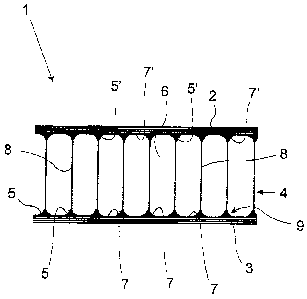
The invention is shown schematically in the single drawing.
Here in a section the airplane component according to the
invention is shown.
In the single figure the airplane component 1 according to
the invention is shown in a vertical section. The
representation has a full scale of about 1 : 1.
The airplane component 1 hexe consists of an interior
laminate 2, an exterior laminate 3, and a honeycomb core 4
CA 02577216 2007-02-06
8
arranged between, interior lami,nate 2 and exterior laminate
3.
The interior as well as the exterior laminate 2, 3 here
consist of a number layers of fiber mats arranged one above
the other, for example of glass or carbon fibers, which are
connected to each other by a matrix. As matrix, for example,
a resin, a synthetic or epoxy resin is provided. Interior.as
well as exterior laminate 2, 3 are here indeed realised in
multiple layers, wherein in particular the innermost or also
the outermost layers of the laminates may have additional
qualities by integrating additional materials.
The honeycomb core 4 has a height of about 5 mm to 50 mm.
Seen in a top view the honeycomb core 4 consists of a number
of tetragonal or hexagonal designed honeycomb cells 6
arranged one next to the other. The design of the honeycombs
here is, by the way, possible in any way.
The single honeycomb cells 6 are each separated from each
other by the honeycomb walls 8. The single honeycomb cells 6
are closed by the interior laminate 2 or the exterior
laminate 3.
The side of the interiax laminate 2 or the exterior laminate
3 facing the honeycomb core 4 is two-dimensionally coated or
covered with a layer of con,nection resin 7. The connection
resin here is preferably identical with the matxix niatexial
of the composite material of the interior 7,aminate 2 or the
exterior laminate 3. It is, of course, possible izi addition,
to that to use other material than the connection resin 7
which can be connected, on the one hand, compatibly with the
interior laminate 2 or the exterior laminate 3, and, on the
other hand, guarantees a sufficient mechanical stability as
high as possible.
The honeycomb wall 8 is pressed with a certain power to the
respective laminate in such a way that the end region 9 of
the honeycomb wall 8 is pressed in the layer of connection
resin, 7. Here, of course, all end regions of the honeycomb
walls 8 are pressed in the same way in the connection resin
7. The connection resin 7 here is n,ot yet completely
hardened, however, not so liquid as shortly after applying.
By rneans of a suitable drying period after applying of the
connection resin the viscosity may be set, and thus the
design of the fastening meniscus 5, 5' which form at the
side next to the honeycomb wall 8 in the end region 9 of the
honeycomb wall. It is convenient here that the connection
resin 7 xises automatically on the honeycomb wall 8 to the
top or the bottom, that means it moves or rises along, and
thus forms the design of the fastening meniscus, and forms a
mechanical connection which can be loaded.
CA 02577216 2007-02-06
9
At the same time the connection resin 7 seals the gap region
between the bottom edge of the honeycomb wal], 8 to the
respecti,ve laminate 2, 3 gas-tight. The single honeycomb
cells 6 thus are independent from each other and gas-tight.
According to the manufacturing method according to the
invention it has been found here that the fastening meniscus
5, 5' are formed at the exterior laminate 3, in, this example
on the bottom, as well as at the interior laminate 2
arranged on top (here fastening meniscus 5').