Note: Descriptions are shown in the official language in which they were submitted.
CA 02577243 2012-10-05
94270-2
TITLE OF THE INVENTION
Pre-curved Catheter Clip and Methods of Using Same
FIELD OF THE INVENTION
[0001]
[0002] This invention relates to medical devices and more specifically
to pre--curved
catheters and the use of a device to properly maintain the shape of a pre-
curved catheter and to
protect the catheter from damage during sterilization and packaging.
BACKGROUND OF THE INVENTION
[0003] In the manufacture of certain catheters, it is desirable to
provide a curved
shape thereto between the proximal and distal ends. When a stylet is installed
into such a
catheter assembly during manufacture to later assist in the insertion of the
catheter into a
patient, the stylet is sufficiently stiff that it tends to try to straighten
the curvature of the
catheter assembly that is desired. Therefore, it is desired to provide for
maintaining the
curvature of the catheter assembly during sterilization, packaging and
shipping.
SUMMARY OF THE INVENTION
[0003a] In one aspect of the invention, there is provided a clip for a pre-
curved
catheter, comprising: a first generally straight body portion defining a first
catheter-receiving
channel portion with a first longitudinal axis extending therethrough and a
longitudinal opening
into the first catheter-receiving channel portion facing in a given direction
and having a
retaining section of the opening having a width less than a maximum width of
the first catheter-
receiving channel portion, the retaining section extending less than a
longitudinal length of the
first catheter-receiving channel portion; a second generally straight body
portion defining a
second catheter-receiving channel portion with a second longitudinal axis
extending
CA 02577243 2012-10-05
94270-2
therethrough and a longitudinal opening into the second catheter-receiving
channel portion
facing in the given direction and having a retaining section of the opening
having a width less
than a maximum width of the second catheter-receiving channel portion, the
retaining section
extending less than a longitudinal length of the second catheter-receiving
channel portion; and
a curved connecting portion connecting the first generally straight body
portion and the second
generally straight body portion such that the second longitudinal axis is
generally parallel with
and spaced from the first longitudinal axis and wherein the connecting portion
defines a
catheter-receiving channel portion such that a continuous channel extends
through the first
generally straight body portion, the connecting portion, and the second
generally straight body
portion.
[0004] In another aspect of the invention, there is provided in
combination, a clip
and a catheter having a pre-curved portion, comprising: a catheter having a
pre-curved portion
and first and second straight portions on opposed sides of the pre-curved
portion, each of the
first and second straight portions having a respective outside diameter; and a
clip having: a first
generally straight body portion defining a first catheter-receiving channel
portion with a first
longitudinal axis extending therethrough and a longitudinal opening into the
first catheter-
receiving channel portion facing in a given direction and having a retaining
section of the
opening having a width less than the outside diameter of the catheter first
straight portion, the
retaining section extending less than a longitudinal length of the first
catheter-receiving channel
portion; a second generally straight body portion defining a second catheter-
receiving channel
portion with a second longitudinal axis extending therethrough, and a
longitudinal opening into
the second catheter-receiving channel portion facing in the given direction
and having a
retaining section of the opening having a width less than the outside diameter
of the catheter
second straight portion, the retaining section extending less than a
longitudinal length of the
second catheter-receiving channel portion; and a curved connecting portion
connecting the first
generally straight body portion and the second generally straight body portion
such that the
second longitudinal axis is generally parallel with and spaced from the first
longitudinal axis
and wherein the connecting portion defines a catheter-receiving channel
portion such that a
continuous channel extends through the first generally straight body portion,
the connecting
portion, and the second generally straight body portion.
2
CA 02577243 2012-10-05
94270-2
[0005] In one embodiment of the present invention, the extension
portion extends
around a curve that defines the desired curve of the catheter to be
maintained, in which case the
U-shaped channel extends continuously from the first generally straight
portion through the
extension to the second generally straight portion, and the extension piece
may include an
additional locking clasp. In another embodiment, the extension piece extends
directly between
the first and second generally straight portions, and the catheter is not
disposed along the
extension piece.
2a
CA 02577243 2007-02-15
WO 2006/026290 PCT/US2005/030062
BRIEF DESCRIPTION OF THE DRAWINGS
[0007] The accompanying drawings, which are incorporated herein and constitute
part of
this specification, illustrate the presently preferred embodiments of the
invention, and, together with
the general description given above and the detailed description given below,
serve to explain the
features of the invention. In the drawings:
[0008] Fig. 1 is a perspective view of a pre-curved catheter clip according to
a first
preferred embodiment of the present invention;
[0009] Fig. 2 is a top plan view of a catheter without the aid of the pre-
curved catheter clip
of Fig. 1;
[0010] Fig. 3 is a top plan view of the pre-curved catheter clip of Fig. 1,
with a Catheter
disposed therein;
[0011] Fig. 4 is a front profile view of the pre-curved catheter clip of Fig.
1;
[0012] Fig. 5 is an enlarged top plan view of the pre-curved catheter clip of
Fig, 3;
[0013] Fig. 6 is a perspective view of a pre-curved catheter clip according to
a second
preferred embodiment of the present invention; and
[0014] Fig. 7 is a perspective view of the clip of Fig. 6, with a catheter
inserted therein.
DETAILED DESCRIPTION OF THE INVENTION
[0015] In the drawings, like numerals indicate like elements throughout. The
terminology
includes the words specifically mentioned, derivatives thereof and words of
similar import. The
embodiments illustrated below are not intended to be exhaustive or to limit
the invention to the
precise form disclosed. These embodiments are chosen and described to best
explain the principle
of the invention and its application and practical use and to enable others
skilled in the art to best
3
CA 02577243 2007-02-15
WO 2006/026290 PCT/US2005/030062
utilize the invention. As used herein, the word "distal" is defined as being
close to the insertion end
of a catheter, and the word "proximal" is defined as being close to the end of
the catheter that
generally remains outside of the body.
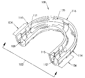
[0016] Referring to Fig. 1, a pre-curved catheter clip 100 according to a
first embodiment
of the present invention is shown. The pre-curved catheter clip 100 is used to
protect, and maintain
the curved shape of a pre-curved catheter during sterilization, packaging, and
shipping. Typically, a
pre-curved catheter 50 having a proximal end 52 and a distal end 54, as shown
in Fig. 2, has a
curved lumen portion 56 extending between the proximal end 52 and the distal
end 54 that is
formed during catheter manufacture. The catheter 50 is preferably a dual lumen
catheter having
two lumens, such as side-by-side or co-axial lumens, although those skilled in
the art will recognize
that the catheter 50 may be a single lumen catheter or a catheter having more
than two lumens.
[0017] A stylet 60 is inserted through the catheter 50. The stylet 60 provides
stiffening
support for the catheter 50 during insertion of the catheter 50 into a patient
during catheterization of
the patient. Ideally, the proximal end 52 and the distal end 54 of the
catheter 50 are generally
parallel to each other. However, as seen in Fig. 2, the proximal end 52 and
the distal end 54 of the
catheter 50 are approximately 45 degrees out of parallel. The stylet 60 is
straight, and tends to at
least partially straighten the catheter 50 after the stylet 60 is inserted
thereinto, resulting in the
approximate 45 degree angle of the distal end 54 of the catheter with respect
to the proximal end 52
of the catheter 50. The catheter clip 100 according to the present invention
is used to maintain the
proximal end 52 and the distal end 54 of the catheter 50 in a generally
parallel relationship during
packaging, sterilization, and shipping, as shown in Fig. 3.
[0018] Referring back to Fig. 1, the pre-curved catheter clip 100 includes a
body 102. The
body 102 includes a first straight portion 104 and a second straight portion
106. The first straight
4
CA 02577243 2007-02-15
WO 2006/026290 PCT/US2005/030062
portion 104 includes a first open end 108 and a first connection end 110. The
first straight portion
104 also includes a first longitudinal axis 111 extending therethrough. The
second straight portion
106 includes a second open end 112 and a second connection end 114, and also
includes a second
longitudinal axis 115 extending therethrough, generally parallel to the first
longitudinal axis 111.
Preferably, the first and second straight portions 104, 106 are each
approximately 1.27 cm (0.50
inches) long, although those skilled in the art will recognize that the first
and second straight
portions 104, 106 may be longer or shorter than 1.27 cm. A curved connecting
portion 116
connects the first and second connection ends 110, 114. Preferably, the
connecting portion 116 has
a bend radius of approximately 1.60 cm (0.63 inches) in order to maintain
curvature of a pre-curved
catheter installed in the clip 100, but without kinking the catheter.
[0019] A channel 120 extends through the body 102 from the first open end 108,
through
the first straight portion 104, the connecting portion 116 and the second
straight portion 106, to the
second open end 112. As seen in Fig. 4, the channel 120 is generally "U-
shaped" in cross section.
The channel 120 includes an outer wall 122 and an inner wall 124. Bottom
portions 122a, 124a of
each of the outer wall 122 and the inner wall 124 are connected to each other
by a generally curved
foundation 126.
[0020] At least one retention section is defined on each of the first and
second generally
straight portions 104,106. The retention section may be a locking clasp or
pair of cooperating
locking clasps, or may be a force fit between opposing walls of each of
portions 104,106, or may be
a latch arm or the like. Preferably, at least one locking clasp assembly 130
extends from each of the
outer wall 122 and the inner wall 124. However, those skilled in the art will
recognize that more
than one locking clasp assembly 130 may be used as part of the general
principle of the invention.
Fig. 5 shows three locking clasp assemblies 130, with the first locking clasp
assembly 130 on the
CA 02577243 2007-02-15
WO 2006/026290 PCT/US2005/030062
first straight portion 104, the second locking clasp assembly 130 on the
second straight portion 106,
and the third locking clasp assembly 130 on the connecting portion 116, as a
non-limiting example
of the number and locations of locking clasp assemblies 130 mounted on the
body 102.
[0021] Each locking clasp assembly 130 preferably includes a locking clasp 132
disposed
on the outer wall 122 and a locking clasp 132 extending from the inner wall
124. However, those
skilled in the art will recognize that each locking clasp assembly 130 may
consist of only one
locking clasp 132 extending from either the outer wall 122 or the inner wall
124, with a
corresponding locking clasp 132 on the inner wall 124 or the outer wall 122
being omitted.
[0022] Referring back to Fig. 4, each locking clasp includes a tapered portion
134 that
extends upward from bottom portion of its respective outer wall 122 or inner
wall 124 into the
channel 120. A cantilevered portion 136 extends from the tapered portion 134
into the channel 120.
A cutout 138 is formed in the foundation 126 directly below each locking clasp
assembly 130. The
cutout 138 facilitates insertion and removal of the catheter 50 from the clip
100 by allowing the clip
100 to flex in the proximity of the cutout 138.
[0023] Preferably, the channel 120 has a diameter sufficient to accept a
catheter of varying
sizes, and the locking clasp assembly 130 is able to retain such catheters
within the channel 120.
Preferably, the clip 100 may be used on catheters varying between 12 and 16
French, although
those skilled in the art will recognize that the dimensions of the clip may be
modified to accept and
retain larger or smaller catheters.
[0024] Preferably, the pre-curved catheter clip 100 is constructed from a
polymer, such as
polypropylene. However, the use of any other polymer or similar material of a
life strength and
composition is also within extent of the present invention.
6
CA 02577243 2007-02-15
WO 2006/026290 PCT/US2005/030062
[0025] To insert the catheter 50 into the clip 100, the lumens of the catheter
50 are forced
past each of the locking clasp assemblies 130 and into the channel 120. The
cutout 138 proximate
to each locking clasp assembly 130 allows the body 102 of the clip 100 to flex
sufficiently to allow
the catheter 50 to be inserted into the channel 120. Once the catheter 50 is
secured within the pre-
curved catheter clip 100, the catheter 50 is ready for sterilization and
packaging.
[0026] When the catheter 50 is ready for use on a patient, the pre-curved
catheter clip 100
must be removed from the catheter 50 before insertion. One method of removing
the catheter 50
from the pre-curved catheter clip 100 involves forcing the lumens past the
cantilevered portion 136
of each locking clasp 132. Once the catheter 50 is fully removed from the
locking clasps 132, the
catheter 50 is ready for insertion into a patient.
[0027] Another method for the removal of the catheter 50 from the clip 100 is
to pull the
catheter lumens through the channel 120 from the proximal end 52 of the
catheter 50. The pulling
of the lumens allows the distal end 54 of the catheter 50 to enter into the
first open end 108 of the
- -
body 102. The distal end 120 of the catheter then passes through the channel
120, underneath of all
of the locking clasp assemblies 130 and then exits the channel 120 through the
second open end
112. Upon removal of the catheter 50 from the clip 100, the catheter 50 is now
ready for insertion
into the patient and the clip 100 is discarded.
[0028] A second embodiment of a pre-curved catheter clip 200 of the present
invention is
shown in Figs. 6 and 7. The clip 200 includes a body 202. The body 202
includes a first generally
straight portion 204 and a second generally straight portion 206. The first
generally straight portion
204 includes a first proximal end 208 and a first distal end 210. The first
generally straight portion
204 also includes a first longitudinal axis 211 extending therethrough. The
second generally
straight portion 106 includes a second proximal end 212 and a second distal
end 214, and also
7
CA 02577243 2007-02-15
WO 2006/026290 PCT/US2005/030062
includes a second longitudinal axis 215 extending therethrough, generally
parallel to the first
longitudinal axis 211. Preferably, the first and second generally straight
portions 204, 206 are each
approximately 1.27 cm (0.50 inches) long, although those skilled in the art
will recognize that the
first and second generally straight portions 204, 206 may be longer or shorter
than 1.27 cm.
[0029] The first generally straight body portion 204 and the second generally
straight body
portion 215 each have a generally "C-shaped" cross-section. The C-shape of the
first generally
straight body portion 204 foul's a first channel 220. The C-shape of the
second generally straight
body portion 215 forms a second channel 222. The first generally straight body
portion 204
includes two juxtaposed edges 224, 226 across the longitudinal axis 211. The
second generally
straight body member also includes two juxtaposed edges 228, 230 across the
second longitudinal
axis 215. The first generally straight body portion 204 acts as a first
locking clasp and the second
generally straight body portion 206 acts as a second locking clasp. The C-
shaped cross-sections
retain a catheter within the channels 220, 222. An extension brace 240
connects the first and
second generally straight body portions 204, 206 and extends generally
perpendicular to the first
and second longitudinal axes 211, 215.
[0030] Preferably, the channels 220, 222 each have a diameter sufficient to
accept a
catheter of varying sizes. Preferably, the clip 200 may be used on catheters
varying between 12 and
16 French, although those skilled in the art will recognize that the
dimensions of the clip may be
modified to accept and retain larger or smaller catheters.
[0031] Preferably, the pre-curved catheter clip 200 is constructed from a
polymer, such as
polypropylene. However, the use of any other polymer or similar material of a
life strength and
composition is also within extent of the present invention.
8
CA 02577243 2007-02-15
WO 2006/026290 PCT/US2005/030062
[0032] The catheter 50 described above with respect to the clip 100 may also
be used in
respect to the second embodiment of the clip 200. To install the catheter 50
into the clip 200, the
catheter 50 is pressed against the two juxtaposed edges 224, 226 of the first
generally straight body
portion 204 and forced into the first channel 220. The catheter 50 is then
pressed against the two
juxtaposed edges 228, 230 of the second generally straight body portion 206
and forced into the
second channel 222. The catheter 50 is now secured within the pre-curved
catheter clip 200, as
shown in Fig. 7, and the catheter 50 is ready for packaging and sterilization.
[0033] The catheter 50 must be removed from the clip 200 before the use of the
catheter 50
on a patient. To remove the catheter 50 from the clip 200, the catheter 50 is
forced past the two
juxtaposed edges 224, 226 of the first generally straight body portion 204 and
the catheter 50 is
removed from the first channel 220. The catheter is then forced past the two
juxtaposed edges 228,
230 of the second generally straight body portion 206 and the catheter 50 is
removed from the
second channel 222.
[0034] Another method of removing the catheter 50 from the clip 200 is to pull
the distal
end 54 of the catheter 50 from the first distal end 210, through the first
distal channel 220, and out
the first proximal end 208 of the first generally straight portion 204. Then,
the distal end 54 of the
catheter 50 is pulled from the second distal end 214, through the second
distal channel 222, and out
of the second proximal end 212 of the second generally straight portion 206.
[0035] It will be appreciated by those skilled in the art that changes could
be made to the
embodiments described above without departing from the broad inventive concept
thereof. It is
understood, therefore, that this invention is not limited to the particular
embodiments disclosed, but
it is intended to cover modifications within the spirit and scope of the
present invention as defined
by the appended claims.
9