Note: Descriptions are shown in the official language in which they were submitted.
CA 02577354 2007-02-06
1
FOLDING TYPE PACKAGE BOX FOR DISPLAY
CROSS-REFERENCE TO RELATED APPLICATION
This application claims priority of Chinese
Application No. 200620043937.8, filed on July 14, 2006.
BACKGROUND OF THE INVENTION
1. Field of the Invention
The invention relates to a package box, more
particularly to a folding type package box for display.
2. Description of the Related Art
To facilitate fabrication, a conventional package
box has only opposite front and rear plates, and a bottom
plate interconnecting the front and rear plates. Each
of the front and rear plates has an outer surface that
is usually printed with pictures and advertisement
relating to an article received in the conventional
package box. In such a configuration, if each of the
front and rear plates has a relatively large width, since
the outer surface of the front or rear plate needs to
face consumers, the position of the conventional package
box is hard to adjust in a limited space for display.
Furthermore, the article received in the conventional
package box is hard to be anchored thereto.
SUNIlMARY OF THE INVENTION
Therefore, the object of the present invention is
to provide a package box that can overcome the aforesaid
drawbacks of the prior art.
According to the present invention, a package box
CA 02577354 2007-02-06
2
comprises:
a rectangular bottom wall having front and rear edges;
front and rear walls connected respectively to the
front and rear edge of the bottom wall along front and
rear folding lines, each of the front and rear walls
having a connecting lateral edge and an engaging lateral
edges opposite to each other, and a top edge, the
connecting and engaging lateral edges of one of the front
and rear walls corresponding respectively to the
engaging and connecting lateral edges of the other one
of the front and rear walls, each of the front and rear
walls being formed with a holding hole adjacent to the
top edge; and
opposite two lateral walls connected respectively
to the connecting lateral edges of the front and rear
walls along lateral folding lines, each of the lateral
walls having an engaging side opposite to the connecting
lateral edge of the respective one of the front and rear
walls and connected detachably to the engaging lateral
edge of the other one of the front and rear walls.
The bottom, front and rear walls, and the lateral
walls cooperatively define an accommodating space
thereamong. The package box is unitary, and is capable
of being unfolded so as to allow the bottom wall, the
lateral walls, and the front and rear walls to be
positioned on a plane.
BRIEF DESCRIPTION OF THE DRAWINGS
CA 02577354 2007-02-06
3
Other features and advantages of the present
invention will become apparent in the f ollowing detailed
description of the preferred embodiment with reference
to the accompanying drawings, of which:
Figure 1 is a perspective view showing the preferred
embodiment of a package box according to the present
invention;
Figure 2 is a schematic top view showing the preferred
embodiment when in a fully unfolded state;
Figure 3 is a perspective view showing the preferred
embodiment when in a semi-unfolded state;
Figure 4 is a fragmentary perspective view showing
the preferred embodiment; and
Figure 5 is a schematic front view showing the
preferred embodiment when in a state of use.
DETAILED DESCRIPTION OF THE PREFERRED EMBODIMENT
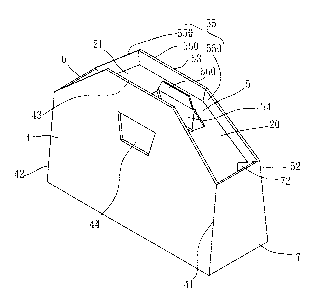
Referring to Figures 1 to 3, the preferred embodiment
of a package box according to the present invention is
shown to include a rectangular bottom wall 3, front and
rear walls 4, 5, and opposite two lateral walls 6, 7.
In this embodiment, the package box is adapted for
receiving an article, such as bundled electric wires
10, therein, as shown in Figure 5.
The bottom wall 3 has front and rear edges 31, 32.
The front and rear walls 4, 5 are connected
respectively to the front and rear edges 31, 32 of the
bottom wall 3 along front and rear folding lines (Ll,
CA 02577354 2007-02-06
4
L2) Each of the front and rear walls 4, 5 has a
connecting lateral edge 41, 51 and an engaging lateral
edge 42, 52 opposite to each other, a top edge 43, 53,
and an inner surface 40, 50 . The connecting and engaging
lateral edges 41, 42 of the front wall 4 correspond
respectively to the engaging and connecting lateral
edges 52, 51 of the rear wall S. Each of the front and
rear walls 4, 5 is formed with a holding hole 44, 54
adjacent to the top edge 43, 53. In this embodiment,
each of the front and rear walls 4, 5 further has a first
flap unit 45, 55, a second flap unit 46, 56, and an engaging
flap 47, 57.
For the front wall 4, the first flap unit 45 includes
a plurality of flaps 450 connected to the top edge 43
along a top folding line (L5) and foldable toward the
inner surface 40. The second flap unit 46 includes a
plurality of flaps 460 connected to a wall portion
defining the holding hole 44 along a folding line (L7)
and foldable toward the inner surface 40. The engaging
flap 47 is connected to the engaging edge 42 and is formed
with an engaging slot 470.
For the rear wall 5, the first flap unit 55 includes
a plurality of flaps 550 connected to the top edge 53
along a top folding line (L6) and foldable toward the
inner surface 50. The second flap unit 56 includes a
plurality of flaps 560 connected to a wall portion
defining the holding hole 54 along a folding line (L8)
CA 02577354 2007-02-06
and foldable toward the inner surface 50. The engaging
flap 57 is connected to the engaging lateral edge 52
and formed with an engaging slot 570.
The lateral walls 7, 6 are connected respectively
5 to the connecting lateral edges 41, 51 of the front and
rear wa-lls 4, 5 along lateral folding lines (L3, L4 ).
The lateral wall 7 has an engaging side 71 opposite
to the connecting lateral edge 41 of the front wall 4
and connected detachably to the engaging lateral edge
52 of the rear wall 5. In this embodiment, the engaging
side 71 of the lateral wall 7 has an engaging tab 73
engaging detachably the engaging slot 570 in the engaging
flap 57 of the rear wall 5 so as to maintain a relative
position among the front and rear walls 4, 5, and the
lateral wall 7, as shown in Figure 4. The lateral wall
7 has a top side 74, and a bottom side 75 opposite to
the top side 74 and having a width larger than that of
the top side 74. The engaging side 71 of the lateral
wall 7 further has an extension wall portion 72 connected
thereto along an upright folding line (L7) and formed
with a positioning slot 721 that extends along a middle
portion of the upright folding line (7) and that has
an enlarged middle slot portion 7211, as shown in Figure
3. The engaging flap 57 of the rear wall 5 extends
through the positioning slot 721 in the extension wall
portion 72. The engaging tab 73 of the lateral wall
7 is engagable fittingly within the enlarged middle slot
CA 02577354 2007-02-06
6
portion 7211 of the positioning slot 721 in the extension
wall portion 72 when the package box is unfolded, as
shown in 2.
The lateral wall 6, similar to the lateral wall 7,
has an engaging side 61 opposite to the connecting
lateral edge 51 of the rear wall 5 and connected
detachably to the engaging lateral edge 42 of the front
wall 4. In this embodiment, the engaging side 61 of
the lateral wall 6 has an engaging tab 63 engaging
detachably the engaging slot 470 in the engaging flap
47 of the front wall 4 so as to maintain a relative position
among the front and rear walls 4, 5, and the lateral
wall 6. The lateral wall 6 has a top side 64, and a
bottom side 65 opposite to the top side 64 and having
a width larger than that of the top side 64. The engaging
side 61 of the lateral wall 6 further has an extension
wall portion 62 connected thereto along an upright
folding line (L8) and formed with a positioning slot
621 that extends along a middle portion of the upright
folding line (L8) and that has an enlarged middle slot
portion 6211, as shown in Figure 3. The engaging flap
47 of the front wall 4 extends through the positioning
slot 621 in the extension wall portion 62. The engaging
tab 63 of the lateral wall 6 is engagable fittingly within
the enlarged middle slot portion 6211 of the positioning
slot 621 in the extension wall portion 62 when the package
box is unfolded, as shown in Figure 2.
CA 02577354 2007-02-06
7
The package box further includes two reinforcing
flaps 8, 9 connected respectively to bottom edges 66,
76 of the lateral walls 6, 7 along bottom folding lines
(L10, L9) and overlying the bottom wall 3, as shown in
Figures 3 and 4.
In such a configuration, the front and rear walls
4, 5, and the lateral walls 7, 6 cooperatively define
an accommodating space 20 thereamong. In this
embodiment, the package box is unitary, and is capable
of being unfolded so as to allow the bottom wall 3, the
lateral walls 6, 7 and the front and rear walls 4, 5
to be positioned on a plane, as shown in Figure 2.
Referring further to Figure 5, in actual use, the
bundledelectricwiresl0disposedin the accommodating
space 20 in the package box can be securely anchored
to the front and rear walls 4, 5 by two bonding straps
11 that pass through the holding holes 44, 54 in the
front and rear walls 4, 5.
In sum, since the top side 64, 74 of each of the lateral
walls 6, 7 is smaller than the bottom sides 65, 75 of
the lateral walls 6, 7, the accommodating space 20
converges toward the top edges 43, 53 of the front and
rear walls 4, 5, and the article can be easily limited
in the accommodating space 20 in the package box. The
package box of the present invention has an upper open
side 21 such that the article disposed in the
accommodating space 20 can be seen by consumers. The
CA 02577354 2007-02-06
8
package box of this invention has a relatively large
outer surface that includes outer surfaces of the front,
rear, and lateral walls 4, 5, 6, 7 and that can be printed
with pictures and advertisement relating to the article
received in the package box. In order to place the
package box in a limited space together with others for
display, one of the lateral walls 6, 7 can be selected
to face consumers as a result of its smaller area.
While the present invention has been described in
connection with what is considered the most practical
and preferred embodiment, it is understood that this
invention is not limited to the disclosed embodiment
but is intended to cover various arrangements included
within the spirit and scope of the broadest
interpretation soas to encompass all such modifications
and equivalent arrangements.