Note: Descriptions are shown in the official language in which they were submitted.
CA 02577576 2007-02-08
Atty Dkt. No.: 07693 6-0103
ADJUSTABLE MOUNTING CART FOR A WHITEBOARD AND PROJECTOR
FIELD
[0001] The subject of the disclosure relates generally to a device for
mounting a whiteboard and a projector. More specifically, the disclosure
relates to a
portable mounting cart in which a whiteboard and/or a projector can be used in
a plurality of
positions.
BACKGROUND
100021 The use of electronic whiteboards is becoming more and more
prevalent in corporate, factory, classroom, and other collaborative
environments. An
electronic whiteboard provides users with an interactive touch screen upon
which a variety
of actions can be performed. For example, electronic whiteboards are able to
receive a
projected image of a computer screen such that users can remotely control
computer
applications by touching the whiteboard. Electronic whiteboards can also allow
users to
annotate documents and web pages, take notes, save annotations and notes, give
presentations, collaborate on-site or across a distance, etc.
[0003] In an educational environment, a whiteboard is an invaluable tool
which can be used by students, teachers, and professors to enhance learning. A
teacher can
use the whiteboard to present notes, share information stored in computer
applications, play
video, browse the Internet, etc. Teachers can also have students walk up to
the front of the
class and interact with the whiteboard. In a typical classroom environment,
the whiteboard
is statically, vertically mounted on a classroom wall much in the same way as
a traditional
blackboard. A projector for projecting images onto the whiteboard is placed in
front of and
at some distance from the whiteboard. Unfortunately, this traditional
projector/whiteboard
arrangement inherently excludes a subset of students from interacting with the
whiteboard
and limits the overall effectiveness of the whiteboard.
[0004] It can be difficult or impossible for a student that is disabled, in a
wheelchair, or on crutches to interact with a whiteboard which is statically,
vertically
mounted on a wall. Traditional whiteboards cannot be lowered, tilted, or moved
to
accommodate such students. As a result, students of limited means are
prevented from
MADI_714639.2 I
CA 02577576 2007-02-08
Atty Dkt. No.: 07693 6-0103
interacting with the rest of their classmates. Further, utilizing a single
whiteboard in a
manner similar to a blackboard allows only one or a few students in the
classroom to
interact with the whiteboard at a given time. In addition, the position of the
projector makes
it easy for lectures to be disrupted as images from the projector are blocked
by the lecturer,
passersby, student movements such as raising a hand, etc.
[0005] In a work environment, in addition to being used as a teaching and
presenting tool, whiteboards are also used to facilitate collaboration among
coworkers. A
group of workers can gather around the whiteboard and utilize the touch screen
to control
computer applications, design products, edit documents, compose documents and
presentations, etc. In a typical workplace, whiteboards are statically,
vertically mounted to
an office or board room wall. Similar to a classroom environment, a projector
for projecting
images onto the whiteboard is placed in front of and at some distance from the
whiteboard.
As with students, it can be difficult or impossible for workers of limited
means to take
advantage of whiteboards which are statically, vertically mounted. Further,
mounted
whiteboards are not portable in the sense that they can easily be moved from
one room to
another or from one plant to another. Such immobility is inconvenient and can
force a
company to purchase more whiteboards than it needs. In addition, when a group
of
coworkers gathers around the whiteboard, images projected from the projector
are often
blocked. It can also be uncomfortable for a group of people to stand in front
of a vertically
mounted whiteboard for any length of time.
[0006] Thus, there is a need for a portable whiteboard mounting cart in
which a whiteboard can be adjusted such that an interactive surface of the
whiteboard can be
in any of a plurality of planes relative to a surface. Further, there is a
need for a portable
whiteboard mounting cart to which a projector can be mounted such that images
can be
projected from above the whiteboard.
SUMMARY
[0007] A device for mounting a whiteboard and a projector is provided. The
device comprises a base and a pole mounted to the base such that the pole is
substantially
perpendicular to a surface. The base comprises a transport mechanism which
allows the
device to be moved from a first location on the surface to a second location
on the surface.
The pole comprises a first mounting bracket and a second mounting bracket. The
first
mounting bracket is for mounting a whiteboard such that an interactive surface
of the
MADI_714639.2 2
CA 02577576 2007-02-08
Atty Dkt. No.: 07693 6-0103
whiteboard is capable of being positioned in a plane of a plurality of planes,
including a
receiving plane. The second mounting bracket is for mounting a projector such
that the
projector is capable of projecting onto the whiteboard while the interactive
surface of the
whiteboard is positioned in the receiving plane.
100081 A device for providing an interactive work environment is also
provided. The device comprises a whiteboard and the above-described device for
mounting
a whiteboard and a projector. A method of assembling an interactive work
station is also
provided. The method comprises providing the above-described device for
mounting a
whiteboard and a projector, and mounting a whiteboard to the device.
[0009] Other principal features and advantages will become apparent to
those skilled in the art upon review of the following drawings, the detailed
description, and
the appended claims.
BRIEF DESCRIPTION OF THE DRAWINGS
[0010] Exemplary embodiments will hereafter be described with reference to
the accompanying drawings, wherein like numerals denote like elements.
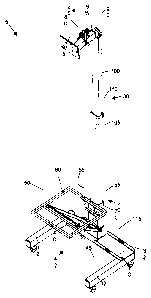
[0011] Fig. lA is a front perspective view of a mounting cart with a
mounting surface in a horizontal position in accordance with an exemplary
embodiment.
[0012] Fig. 1 B is a front perspective view of a stationary mounting cart in
accordance with an exemplary embodiment.
[0013] Fig. 2 is a front perspective view of a mounting cart with the
mounting surface in a vertical position in accordance with an exemplary
embodiment.
[0014] Fig. 3 is a front perspective view of a mounting cart with the
mounting surface positioned at an angle in accordance with an exemplary
embodiment.
[0015] Fig. 4 is a side view of a first mounting bracket in accordance with a
first exemplary embodiment.
[0016] Fig. 5 is a side view of a first mounting bracket in accordance with a
second exemplary embodiment.
[0017] Fig 6 is a side view of a pole adjustment mechanism for a telescoping
pole in accordance with an exemplary embodiment.
MADI_714639.2 3
CA 02577576 2007-02-08
Atty Dkt. No.: 07693 6-0103
[0018] Fig. 7 is a perspective view of a second mounting bracket in
accordance with an exemplary embodiment.
[0019] Fig. 8 is a perspective view of a projector mounted to the second
mounting bracket in accordance with an exemplary embodiment.
[0020] Fig. 9 is a side view of a mounting cart with a whiteboard mounted to
a mounting surface and positioned horizontally in accordance with an exemplary
embodiment.
[0021] Fig. 10 is a front perspective view of the mounting cart with the
whiteboard mounted to the mounting surface and positioned horizontally in
accordance with
an exemplary embodiment.
[0022] Fig. 11 is a side view of a mounting cart with the whiteboard mounted
to the mounting surface and positioned at an angle in accordance with an
exemplary
embodiment.
[0023] Fig. 12 is a front perspective view of the mounting cart with the
whiteboard mounted to the mounting surface and positioned at the angle in
accordance with
an exemplary embodiment.
[0024] Fig. 13 is a side view of a mounting cart with a whiteboard mounted
to the mounting surface and positioned vertically in accordance with an
exemplary
embodiment.
[0025] Fig. 14 is a front perspective view of the mounting cart with the
whiteboard mounted to the mounting surface and positioned vertically in
accordance with an
exemplary embodiment.
[0026] Fig. 15 is a side view of the whiteboard mounted to a wall in
accordance with an exemplary embodiment.
[0027] Fig. 16 is a side view of the whiteboard mounted to the wall at an
angle in accordance with an exemplary embodiment.
[0028] Fig. 17 is a flow diagram illustrating operations performed during an
assembly of an interactive work environment in accordance with an exemplary
embodiment.
MADI_714639.2 4
CA 02577576 2007-02-08
Atty Dkt. No.: 07693 6-0103
DETAILED DESCRIPTION
[0029] Fig. 1 A illustrates a mounting cart 5 in accordance with an exemplary
embodiment. The mounting cart 5 includes a base 10, a first mounting bracket
20, a second
mounting bracket 25, and a telescoping pole 30. The base 10 includes rollers
32 such that
the mounting cart 5 can easily be moved from a first location to a second
location. In an
exemplary embodiment, the mounting cart 5 can include four rollers 32, and one
or more of
the rollers 32 can include a locking mechanism such that the mounting cart 5
can be
immobilized. Alternatively, the mounting cart can include any number of
rollers. In
another alternative embodiment, the mounting cart can be made portable by any
other
transport mechanism(s) known to those skilled in the art. For example, the
transport
mechanism can include any combination of one or more rollers, wheels, skis,
tracks, tires,
etc. The transport mechanism can also include one or more handles such that
the mounting
cart can be pushed, pulled, or rotated. In an alternative embodiment, the
mounting cart can
be stationary. Fig. 1 B illustrates a mounting cart 6 in which a base 7 of the
mounting cart 6
does not include a transport mechanism. The base 7 of the mounting cart 6 can
rest on feet
(not shown), pedestals, or any other platform(s). Alternatively, the base 7 of
the mounting
cart 6 can rest directly on a surface.
100301 Referring back to Fig. IA, the base 10 also includes a first base
member 35, a second base member 40 mounted to the first base member 35, and a
third base
member 45 mounted to the first base member 35. As used in this disclosure, the
term
"mount" can include join, unite, connect, associate, insert, hang, hold,
affix, attach, fasten,
bind, paste, secure, bolt, nail, glue, screw, rivet, solder, weld, and other
like terms. The
second base member 40 and the third base member 45 can be mounted to the first
base
member 35 at right angles to form a partial rectangle such that a clear path
42 is provided.
The clear path 42 allows a wheelchair or other chair to easily be positioned
adjacent to
and/or underneath a mounting surface 50 for receiving a whiteboard. In
alternative
embodiments, any number of base members can be used, and the base members can
be
arranged in any way which provides easy access to a whiteboard mounted to the
mounting
surface. For example, two base members can be arranged in a V shape, three
base members
can be arranged as a triangle, a single, semi-circular base member can be
used, etc. The
base 10 also includes a support surface 115 capable of receiving a computer
box or other
hardware.
MADI_714639.2 5
CA 02577576 2007-02-08
Atty Dkt. No.: 07693 6-0103
[0031] In a first exemplary embodiment, the first mounting bracket 20
includes a lower clamp 70, an upper clamp 65, the mounting surface 50, an
upper mounting
surface stabilizer 55, and a lower mounting surface stabilizer 60. The
mounting surface 50
is capable of receiving a whiteboard (not shown). The upper mounting surface
stabilizer 55
is mounted to both the mounting surface 50 and the upper clamp 65 of the first
mounting
bracket 20. The lower mounting surface stabilizer 60 is mounted to both the
mounting
surface 50 and the lower clamp 70 of the first mounting bracket 20. The lower
clamp 70
and upper clamp 65 are able to slide independently of one another along the
telescoping
pole 30 such that the mounting surface 50 can be positioned in a plurality of
planes relative
to a surface (not shown). The surface can be any ground or floor surface upon
which the
mounting cart 5 is placed. The lower clamp 70 and upper clamp 65 are also able
to slide
along the telescoping pole 30 in tandem such that an overall height of the
mounting surface
50 relative to the surface can be adjusted. As illustrated in Fig. lA, the
mounting surface 50
is positioned in a plane parallel to the surface. The first mounting bracket
20 is described in
more detail with reference to Figs. 4-5.
[0032] In a first exemplary embodiment, the second mounting bracket 25
includes a first bracket leg 75, a second bracket leg 80, a bracket leg
adjustment mechanism
85, a pivot mechanism 90, and a mounting plate 95. The mounting plate 95 is
capable of
receiving a projector (not shown). The mounting plate 95 can be statically or
pivotally
mounted to the second bracket leg 80 depending on the embodiment. The pivot
mechanism
90 allows the first bracket leg 75 to be positioned at a plurality of angles
relative to the
telescoping pole 30. As illustrated in Fig. lA, the first bracket leg 75 is
positioned at a
ninety degree angle relative to the telescoping pole 30. In this position, a
projector mounted
to the mounting plate 95 can project in a downward direction. The bracket leg
adjustment
mechanism 85 allows the second bracket leg 80 to be positioned at a plurality
of angles
relative to the first bracket leg 75. As illustrated in Fig. 1 A, the second
bracket leg 80 is
positioned at approximately a five degree angle relative to the first bracket
leg 75. The
second mounting bracket 25 is described in more detail with reference to Figs.
7-8.
[0033] The telescoping pole 30 includes a first pole section 100, a second
pole section 105, and a pole adjustment mechanism 110. In an exemplary
embodiment, the
first pole section 100 slidably fits into the second pole section 105 such
that a distance
between a mounted projector and a mounted whiteboard can be adjusted via the
pole
adjustment mechanism 110. In an alternative embodiment, the roles of the first
pole section
MADI_714639.2 6
CA 02577576 2007-02-08
Atty Dkt. No.: 07693 6-0103
and the second pole section can be reversed such that the second pole section
slidably fits
into the first pole section. In another alternative embodiment, a non-
telescoping pole can be
used and the first and/or second mounting brackets can slide along the non-
telescoping pole
such that a distance between the projector and the whiteboard can be adjusted.
The
telescoping pole 30 is described in more detail with reference to Fig. 6.
[0034] Fig. 2 illustrates a mounting cart 5 in which the upper clamp 65 and
the lower clamp 70 are positioned such that the mounting surface 50 of the
first mounting
bracket 20 is positioned in a plane perpendicular to a surface (not shown).
Similarly, Fig. 3
illustrates a mounting cart 5 in which the upper clamp 65 and the lower clamp
70 are
positioned such that the mounting surface 50 of the first mounting bracket 20
is positioned
in a plane that is at an angle of approximately fifteen degrees relative to a
surface (not
shown). In an exemplary embodiment, the upper clamp 65 and the lower clamp 70
can be
adjusted such that the mounting surface 50 of the first mounting bracket 20 is
positioned in a
plane that is at any angle between zero (horizontal) and ninety (vertical)
degrees relative to
the surface.
[0035] Fig. 4 illustrates a first mounting bracket 20 in accordance with a
first
exemplary embodiment. The upper clamp 65 includes an upper clamp adjustment
mechanism 200 and the lower clamp 70 includes a lower clamp adjustment
mechanism 205.
The upper clamp adjustment mechanism 200 includes an upper clamp handle 210
and an
upper clamp pin 215. Similarly, the lower clamp adjustment mechanism 205
includes a
lower clamp handle 220 and a lower clamp pin 225. In an exemplary embodiment,
the
telescoping pole 30 can include a plurality of vertically spaced holes to
facilitate height and
angle adjustment of the mounting surface 50. As such, the mounting surface 50
can easily
be placed into a plurality of predetermined positions. The upper clamp 65 can
be secured to
the telescoping pole 30 by pushing the upper clamp handle 210 such that the
upper clamp
pin 215 is inserted into a desired hole in the telescoping pole 30. The
position of the upper
clamp 65 can be adjusted by pulling the upper clamp handle 210 to release the
upper clamp
pin 215, sliding the upper clamp 65 to a desired position along the
telescoping pole 30, and
pushing or releasing the upper clamp handle 210 such that the upper clamp pin
215 is
inserted into a desired hole in the telescoping pole 30. Similarly, the lower
clamp 70 can be
secured and adjusted by using the lower clamp handle 220 to insert the lower
clamp pin 225
into a desired hole in the telescoping pole 30.
MADI_714639.2 7
CA 02577576 2007-02-08
Atty Dkt. No.: 07693 6-0103
[0036] In an alternative embodiment, the upper clamp pin and lower clamp
pin can be threaded. The upper clamp handle and lower clamp handle can be used
to screw
the upper clamp pin and lower clamp pin into threaded holes within the
telescoping pole. In
another alternative embodiment, the upper clamp pin and the lower clamp pin
can be
threaded and the telescoping pole can be without holes such that the mounting
surface can
be placed in any position. The upper clamp and the lower clamp can be secured
to the
telescoping pole by turning the upper clamp handle and the lower clamp handle
such that
the upper clamp pin and the lower clamp pin frictionally contact the
telescoping pole. The
upper clamp pin and the lower clamp pin can also be spring-loaded such that a
spring force
pushes the upper clamp pin and the lower clamp pin toward the telescoping
pole.
Alternatively, the upper clamp and the lower clamp can be movably secured to
the
telescoping pole by any other method known to those skilled in the art.
[0037] The mounting surface 50 is connected to the upper clamp 65 through
the upper mounting surface stabilizer 55. The upper mounting surface
stabilizer 55 includes
a first end 230 mounted to the upper clamp 65 and a second end 235 mounted to
the
mounting surface 50. In an exemplary embodiment, the first end 230 of the
upper mounting
surface stabilizer 55 is statically mounted to the upper clamp 65 and the
second end 235 of
the upper mounting surface stabilizer 55 is pivotally mounted to the mounting
surface 50.
Alternatively, the first end 230 of the upper mounting surface stabilizer 55
can be statically
or pivotally mounted to the upper clamp 65 and the second end 235 can be
statically or
pivotally mounted to the mounting surface 50. Statically mounted can refer to
any fixed
mounting which does not allow translation, rotation, or pivoting of the lower
or upper
mounting surface stabilizer. Pivotally mounted can refer to any mounting which
allows the
lower or upper mounting surface stabilizer to pivot. A pivotal mount can be
provided by a
hinge, pivot bracket, or any other mechanism which enables a pivoting motion.
The
mounting surface 50 is connected to the lower clamp 70 through the lower
mounting surface
stabilizer 60. The lower mounting surface stabilizer 60 includes a first end
240 and a
second end (not shown). In an exemplary embodiment, the first end 240 is
pivotally
mounted to the lower clamp 70 and the second end is pivotally mounted to the
mounting
surface 50. Alternatively, the first end 240 of the lower mounting surface
stabilizer 60 can
be pivotally or statically mounted to the lower clamp 70 and the second end
can be pivotally
or statically mounted to the mounting surface 50.
MADI_714639.2 8
CA 02577576 2007-02-08
Atty Dkt. No.: 07693 6-0103
[0038] Fig. 5 illustrates a first mounting bracket 250 in accordance with a
second exemplary embodiment. The first mounting bracket 250 includes an upper
clamp
255, a lower clamp 260, an upper mounting surface stabilizer 280, a lower
mounting surface
stabilizer 290, and the mounting surface 50. The upper clamp 255 includes an
upper clamp
adjuster 265. The upper clamp adjuster 265 can be mounted to the upper clamp
255 with a
first mounting pin 266 such that an end 267 of the upper clamp adjuster 265
can be raised
and lowered. The end 267 can be raised to frictionally hold the upper clamp
255 to the
telescoping pole 30 or lowered such that the upper clamp 255 can be moved
along the
telescoping pole 30. As illustrated in Fig. 5, the end 267 of the upper clamp
adjuster 265 is
in a lowered position. The lower clamp 260 includes a lower clamp adjuster 270
and a
stopper 275. The lower clamp adjuster 270 can be mounted to the lower clamp
260 with a
second mounting pin 271 such that an end 269 of the lower clamp adjuster 270
can be raised
and lowered. The end 269 of the lower clamp adjuster 270 can be raised to
frictionally hold
the lower clamp 260 to the telescoping pole 30 or lowered such that the lower
clamp 260
can be moved along the telescoping pole 30. As illustrated in Fig. 5, the
lower clamp
adjuster 270 is in a raised position. The stopper 275 can be used to keep a
minimum
distance between the upper clamp 255 and the lower clamp 260 such that the
upper clamp
255 does not interfere with the lower clamp adjuster 270.
[0039] The mounting surface 50 is connected to the upper clamp 255 through
the upper mounting surface stabilizer 280. The upper mounting surface
stabilizer 280
includes a first end 282 mounted to the upper clamp 255 and a second end 285
mounted to
the mounting surface 50. In an exemplary embodiment, the first end 282 of the
upper
mounting surface stabilizer 280 is statically mounted to the upper clamp 255
and the second
end 285 of the upper mounting surface stabilizer 280 is pivotally mounted to
the mounting
surface 50. Alternatively, the first end 282 of the upper mounting surface
stabilizer 280 can
be statically or pivotally mounted to the upper clamp 255 and the second end
285 can be
statically or pivotally mounted to the mounting surface 50. The mounting
surface 50 is
connected to the lower clamp 260 through the lower mounting surface stabilizer
290. The
lower mounting surface stabilizer 290 includes a first end 295 and a second
end (not
shown). In an exemplary embodiment, the first end 295 is pivotally mounted to
the lower
clamp 260 and the second end is pivotally mounted to the mounting surface 50.
Alternatively, the first end 295 of the lower mounting surface stabilizer 290
can be pivotally
MADI_714639.2 9
CA 02577576 2007-02-08
Atty Dkt. No.: 07693 6-0103
or statically mounted to the lower clamp 260 and the second end can be
pivotally or
statically mounted to the mounting surface 50.
[0040] Fig. 6 illustrates a pole adjustment mechanism 110 for the telescoping
pole 30 in accordance with an exemplary embodiment. The pole adjustment
mechanism
110 includes a pole handle 300 and a pole pin 305. In an exemplary embodiment,
the first
pole section 100 of the telescoping pole 30 can include a plurality of
vertically spaced holes
capable of receiving the pole pin 305. The pole handle 300 can be used to
place the pole pin
305 into a hole in the first pole section 100 corresponding to a desired
telescoping pole 30
height. Alternatively, the pole pin can hold the first pole section in place
by frictionally
resting against the first pole section. The pole pin 305 can be spring-loaded,
threaded, or
non-threaded depending on the embodiment. In one embodiment, the telescoping
pole 30
can be used to immobilize the mounting cart. A bottom end of the telescoping
pole 30 can
frictionally contact a surface and/or a top end of the telescoping pole 30 can
frictionally
contact a ceiling surface such that the mounting cart is unable to be moved.
[0041] Fig. 7 illustrates a second mounting bracket 25 in accordance with an
exemplary embodiment. The bracket adjustment mechanism 85 and the pivot
mechanism
90 can be used to place the mounting plate 95 in a desired position such that
a projector
mounted to the mounting plate 95 projects at a desired angle. A pivot
mechanism handle
355 of the pivot mechanism 90 can be used to position the first bracket leg 75
parallel to the
telescoping pole such that a projector mounted to the mounting plate 95 is
capable of
projecting onto a wall independent of the mounting surface 50. The pivot
mechanism
handle 355 can also be used to position the first bracket leg 75 perpendicular
to the
telescoping pole such that a projector mounted to the mounting plate 95 is
capable of
projecting onto a whiteboard mounted to the mounting surface 50. In an
exemplary
embodiment, the pivot mechanism 90 is capable of positioning the first bracket
leg 75
parallel or perpendicular to the telescoping pole. Alternatively, the pivot
mechanism can be
used to position the first bracket leg at any angle relative to the
telescoping pole.
[0042] The bracket adjustment mechanism 85 includes a handle 350 and a
pin 360. The handle 350 can be used to adjust the second bracket leg 80
relative to the first
bracket leg 75 such that a desired angle of projection can be obtained. For
example, if a
whiteboard is mounted to the mounting cart at a fifteen degree angle relative
to a surface,
the bracket adjustment mechanism 85 can be used to position the second bracket
leg 80 at a
fifteen (or other) degree angle relative to the first bracket leg 75 such that
a projector
MADI_714639.2 10
CA 02577576 2007-02-08
Atty Dkt. No.: 07693 6-0103
mounted to the mounting plate 95 can fully project onto the whiteboard. In an
exemplary
embodiment, the pin 360 can be threaded such that an angle between the first
bracket leg 75
and the second bracket leg 80 can be adjusted by turning the handle 350.
Alternatively, the
pin can be unthreaded and the angle between the first bracket leg and the
second bracket leg
can be adjusted by any method known to those skilled in the art. In an
alternative
embodiment, the second mounting bracket can also include a locking mechanism
such that a
projector cannot be easily removed from the mounting plate.
[0043] Fig. 8 illustrates a projector 400 mounted to the second mounting
bracket 25 in accordance with an exemplary embodiment. A projector plate 405
is mounted
onto the mounting plate 95 and the projector 400 is mounted onto the projector
plate 405.
Alternatively, the projector can be mounted directly onto the mounting plate.
In an
exemplary embodiment, the projector 400 can be mounted to the mounting plate
95 or the
projector plate 405 with screws. Alternatively, the projector can be mounted
by any method
known to those skilled in the art. The pivot mechanism 90 is positioned such
that the first
bracket leg 75 is parallel to the telescoping pole 30, and the bracket
adjustment mechanism
85 is positioned such that the angle between the first bracket leg 75 and the
second bracket
leg 80 is one hundred eighty degrees. As such, the projector 400, as
illustrated in Fig. 8, is
positioned to project onto a wall which is independent of the mounting surface
50.
[0044] Fig. 9 is a side view of a mounting cart 425 illustrating a whiteboard
450 mounted to the mounting surface 50 and positioned horizontally in
accordance with an
exemplary embodiment. In an exemplary embodiment, the whiteboard 450 can be
mounted
to the mounting surface 50 with screws. Alternatively, the whiteboard can be
mounted to
the mounting surface in any manner known to those skilled in the art. The
whiteboard 450
can include an interactive surface 455 upon which images can be projected. In
the
exemplary embodiment of Fig. 9, the whiteboard 450 is mounted to the mounting
surface 50
of the first mounting bracket 250. A projector 400 is also mounted to the
mounting cart 425
such that images can be projected onto the interactive surface 455 of the
whiteboard 450.
Fig. 10 is a perspective view of the mounting cart 425 illustrating the
whiteboard 450
mounted to the mounting surface 50 and positioned horizontally in accordance
with an
exemplary embodiment.
[0045] Fig. 11 is a side view of the mounting cart 425 illustrating the
interactive surface 455 of the whiteboard 450 mounted at an angle 502 relative
to a plane A-
A which is parallel to a surface 500 in accordance with an exemplary
embodiment. The
MADI_714639.2 11
CA 02577576 2007-02-08
Atty Dkt. No.: 07693 6-0103
whiteboard 450 is also mounted at a height 504 relative to the surface 500.
The height 504
can refer to a distance between a bottom edge 506 of the interactive surface
455 of the
whiteboard 450 and the surface 500. Alternatively, the height can refer to a
distance
between any portion of the whiteboard and the surface. The angle 502 and the
height 504 of
the interactive surface 455 of the whiteboard 450 relative to the surface 500
can be adjusted
by lowering or raising the lower clamp 260 and/or the upper clamp 255.
[0046] The interactive surface 455 is capable of being positioned in a plane
B-B of a plurality of planes relative to the surface 500. In the exemplary
embodiment of
Fig. 11, the interactive surface 455 is positioned in the plane B-B such that
the angle 502 is
approximately fifteen degrees. In an exemplary embodiment, the plurality of
planes can
include any plane between zero degrees (horizontal) and ninety degrees
(vertical) relative to
the surface 500. Within the plurality of planes is a plurality of receiving
planes. A
receiving plane can refer to any plane in the plurality of planes in which the
interactive
surface 455 is positioned such that the projector 400 mounted to the mounting
cart 425 is
capable of projecting onto the interactive surface 455. In an exemplary
embodiment, an
angle of the receiving plane relative to the surface 500 is less than or equal
to approximately
forty-five degrees when the projector 400 mounted to the second mounting
bracket 25 is
used to project onto the interactive surface 455. In an alternative
embodiment, the receiving
plane can be any plane within the plurality of planes.
[0047] Fig. 12 is a perspective view of the mounting cart 425 illustrating a
whiteboard 450 mounted to the mounting surface 50 and positioned at
approximately a
fifteen degree angle relative to the surface 500 in accordance with an
exemplary
embodiment. Fig. 13 is a side view of the mounting cart 425 illustrating the
whiteboard 450
mounted to the mounting surface 50 and positioned at a ninety degree angle
relative to the
surface 500 in accordance with an exemplary embodiment. As such, the
whiteboard 450 is
capable of receiving images from a projector placed on or mounted to a floor,
wall, ceiling,
table, etc. Fig. 14 is a perspective view of the mounting cart 425
illustrating the whiteboard
450 mounted to the mounting surface 50 and positioned at a ninety degree angle
relative to
the surface 500 in accordance with an exemplary embodiment.
[0048] Fig. 15 illustrates a whiteboard 450 mounted to a wall 550 in
accordance with an exemplary embodiment. A pole 555 is mounted to the wall 550
and a
first mounting bracket 250 is mounted to the pole 555 such that an interactive
surface 455 of
the whiteboard 450 can be adjusted relative to a surface 560. A projector 400
can be
MADI_714639.2 12
CA 02577576 2007-02-08
Atty Dkt. No.: 076936-0103
mounted to a ceiling 565 such that images can be projected downward onto the
interactive
surface 455. Alternatively, a projector can be mounted to or placed on the
ceiling, the
surface, an opposite wall, a table, etc. such that images can be horizontally
projected onto
the interactive surface. Fig. 16 illustrates the whiteboard 450 mounted to the
wall 550 at an
angle in accordance with an exemplary embodiment. The angle is such that the
projector
400 mounted to the ceiling 565 is capable of projecting onto the interactive
surface 455 of
the whiteboard 450.
100491 In an alternative embodiment, the mounting cart can be used to
provide a bedridden individual with access to a whiteboard. In such an
embodiment, the
base of the mounting cart can be positioned under a side of a bed, and the
first mounting
bracket can be adjusted such that the whiteboard is positioned above and
within reach of the
bedridden individual. The whiteboard and the projector can both be mounted to
the
mounting cart such that the whiteboard and the projector are rotated at a
ninety degree angle
relative to the position illustrated with reference to Fig. 10. As such, the
bedridden
individual can view and interact with the whiteboard without having to tilt
his/her head at an
angle.
[00501 Fig. 17 is a flow diagram illustrating operations performed during an
assembly of an interactive work environment in accordance with an exemplary
embodiment.
Additional, fewer, or different operations may be performed depending on the
embodiment.
Further, the use of a flow diagram is not meant to be limiting with respect to
the order of
operations performed. In an operation 600, a mounting cart capable of
receiving a
whiteboard and a projector is provided. The mounting cart can be any of the
mounting carts
described with reference to figures 1-14. In an operation 605, the whiteboard
is mounted to
the mounting cart. The whiteboard can be mounted to a mounting surface of a
first
mounting bracket of the mounting cart. For example, the whiteboard 450 can be
mounted to
the first mounting bracket 20, 250. In an operation 610, the projector is
mounted to the
mounting cart. The projector can be mounted to a mounting plate of a second
mounting
bracket of the mounting cart. For example, the projector 400 can be mounted to
the
mounting plate 95 of the second mounting bracket 25.
100511 The foregoing description of exemplary embodiments has been
presented for purposes of illustration and of description. It is not intended
to be exhaustive
or limiting with respect to the precise form disclosed, and modifications and
variations are
possible in light of the above teachings or may be acquired from practice of
the disclosed
MADI_714639.2 13
CA 02577576 2007-02-08
Atty Dkt. No.: 07693 6-0103
embodiments. It is intended that the scope of the invention be defined by the
claims
appended hereto and their equivalents.
MADI_714639.2 14