Note: Descriptions are shown in the official language in which they were submitted.
CA 02577905 2007-02-21
WO 2006/026599 PCT/US2005/030791
TITLE OF THE INVENTION
CAP ASSEMBLY AND CONTAINER USED THEREWITH
BACKGROUND OF THE INVENTION
1. Field of the Invention
[0001] The present invention relates in general to a cap assembly, and
more
particularly, to a cap assembly capable of hermetically sealing a container
assembly, the cap
assembly undergoing sterilization processes with superheated steam at
temperatures in excess
of 280 F. Such sterilization processes are generally suitable for filling of
food grade flowable
material including low acid flowable material. Of course, the invention is not
limited to any
particular flowable material.
2. Background Art
[0002] The use of flexible containers for the shipment and dispensing of
flowable
material has greatly increased in recent years. Increasingly, flexible
containers are common
for food grade products. Among other procedures, it is necessary to properly
sterilize the
containers to minimize contamination and to maximize shelf life of the
products within the
containers. While the sterilization of containers for high acid products has
been readily
achieved, there have been problems associated with low acid applications. This
is because
high acid products have an inherent advantage; microbes and microorganism have
difficulty
surviving and reproducing in highly acidic materials.
[0003] The same is not true for low acid materials. In particular,
microbes and
microorganisms can thrive in a low acid environment. For this reason, the
sterilization
procedures for containers utilized in low acid environments are substantially
more rigorous
than for high acid environments. In a low acid filling process, for example,
prior to and after
=
1
CA 02577905 2007-02-21
WO 2006/026599 PCT/US2005/030791
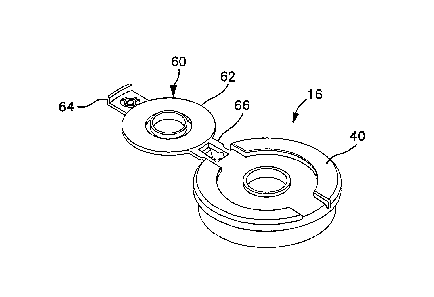
filling, a spout assembly is exposed to superheated steam for a predetermined
period of time.
For example, at a temperature of 280 F, sterilization is achieved after 13
seconds (the steam
is at approximately 30 psi). At 290 F, sterilization is reached in about 3.6
seconds. In excess
of 300 F, sterilization is reached in about 1 second. Temperatures as high as
307 F and
higher (pressure of approximately 60 psi) are utilized to achieve quick
sterilization of
components. It will be understood that if chemicals are added for purposes of
sterilization,
the temperatures required for the steam can be lower.
[0004] Providing covers for fitments which are both suitable for use in
low acid
conditions, and which include openings extending therethrough for dispensing
purposes
which cannot substantially withstand the sterilizing environment has proven
difficult. First,
the seal over the dispensing opening often fails during the sterilizing
procedure. In other
situations, the covers deform in such an environment to the extent that the
cover dislodges or
otherwise disengages from the fitment. In either case, the end result is that
the material within
the container is destroyed and must be discarded.
[0005] Inasmuch as such sterilizing is highly destructive to fitments and
covers,
containers used for low acid applications often include two separate fitments.
The fitment
within which product is to be filled generally includes a cap member free of
openings. A
second fitment is provided on the container for dispensing. Such a fitment
includes a cap
member which is capable of receiving various different dispensers for coupling
therewith.
Inasmuch as no manipulation or. removal of the second (dispensing) fitment is
required
during filling of the container, the second fitment does not undergo the
sterilizing procedures
described above. Problematically, the use of two separate fitments increases
the cost of the
2
CA 02577905 2013-01-21
containers, the assembly of the containers and the ease of manipulation of the
containers.
Furthermore, the greater use of components leads to increased container
failure rates.
[0006] Accordingly, it is an aspect of the invention to provide a cap
assembly for a
flexible container which includes a resealable dispensing means which are
suitable for low
acid applications including sterilization processes which occur at elevated
temperatures with
superheated steam.
[0007] It is another aspect of the invention to provide a cap assembly
adapted for
receipt of a number of different dispensers, wherein the cap assembly which is
suitable for
low acid applications including sterilization processes which occur at
elevated temperatures
with superheated steam.
[0007.1] According to one aspect of the present invention there is provided
a container
assembly, comprising a container having at least one panel and at least one
seal sealing the at
least one panel to define a cavity; a fitment, coupled with the container,
comprising a body
having a first end and a second end, the second end extending away from the
container,
wherein the fitment provides fluid communication with the cavity; a cap
assembly releasably
attachable to the second end of the fitment, the cap assembly comprising: a
base having an
upper surface, a lower surface and an opening extending therethrough, the
lower surface
including an outer retaining rim and an inner retaining rim substantially
concentrically
positioned relative to the outer retaining rim, the outer retaining rim and
the inner retaining
rim defining a channel structurally configured to retain the second end of the
fitment through
an interference fit therebetween, the opening including a lower annular rim
extending from
the lower surface of the base, the lower annular rim defines an elongated
passage spaced
apart from the inner retaining rim and substantially concentric thereto; and a
cover associated
with the base and positioned over the opening to, in turn, cover the opening
of the base
thereby precluding ingress into the elongated passage of the lower annular
rim; a frangible
3
CA 02577905 2013-01-21
cover sealingly attached to an outer perimeter of the lower annular rim of the
opening, the
frangible cover structurally configured to break, peel or dislodge from the
outer perimeter of
the lower annular rim, to, in turn, provide ingress into the cavity of the
container.
[0007.2] According to a further aspect of the present invention there is
provided a
container assembly, comprising a container having at least one panel and at
least one seal
sealing the at least one panel to define a cavity; a fitment, coupled with the
container,
comprising a body having a first end and a second end, the second end
extending away from
the container, wherein the fitment provides fluid communication with the
cavity; a cap
assembly releasably attachable to the second end of the fitment, the cap
assembly comprising:
a base having an upper surface, a lower surface and an opening extending
therethrough, the
opening including an upper annular rim extending from the upper surface of the
base and a
lower annular rim extending from the lower surface of the base; and a cover
attachable to the
base to cover the opening, the cover including an annular ring that extends
along at least a
portion of the upper annular rim of the opening and the lower annular rim of
the opening, the
annular ring forming a hermetic seal with at least one of the upper and lower
annular rims of
the opening; wherein the upper surface of the base includes a shoulder
extending at least
partially around an outer region thereof, the shoulder comprising at least
four spaced apart
shoulder components defining a valley therebetween.
[0007.3] According to another aspect of the present invention there is
provided a cap
assembly releasably attachable to the second end of the fitment, the cap
assembly comprising
a base having an upper surface, a lower surface and an opening extending
therethrough, the
lower surface including an outer retaining rim and an inner retaining rim
substantially
concentrically positioned relative to the outer retaining rim, the outer
retaining rim and the
inner retaining rim defining a channel structurally configured to retain the
second end of the
fitment through an interference fit therebetween, the opening including a
lower annular rim
3a
CA 02577905 2013-01-21
extending from the lower surface of the base, the lower annular rim defines an
elongated
passage spaced apart from the inner retaining rim and substantially concentric
thereto; and a
cover associated with the base and positioned over the opening to, in turn,
cover the opening
of the base thereby precluding ingress into the elongated passage of the lower
annular rim; a
frangible cover sealingly attached to an outer perimeter of the lower annular
rim of the
opening, the frangible cover structurally configured to break, peel or
dislodge from the outer
perimeter of the lower annular rim, to, in turn, provide ingress into the
cavity of the container.
[0007.4] According to a still further aspect of the present invention there
is provided a
container assembly, comprising a container having at least one panel and at
least one seal
sealing the at least one panel to define a cavity; a fitment, coupled with the
container,
comprising a body having a first end and a second end, the second end
extending away from
the container, wherein the fitment provides fluid communication with the
cavity; a cap
assembly releasably attachable to the second end of the fitment, the cap
assembly comprising:
a base having an upper surface, a lower surface and an opening extending
therethrough, the
opening including an upper annular rim extending from the upper surface of the
base and a
lower annular rim extending from the lower surface of the base; and a cover
attachable to the
base to cover the opening, the cover including an annular ring that extends
along at least a
portion of the upper annular rim of the opening and the lower annular rim of
the opening, the
annular ring forming a hermetic seal with at least one of the upper and lower
annular rims of
the opening; wherein the upper surface of the base includes a shoulder
extending at least
partially around an outer region thereof, the shoulder comprising at least
four spaced apart
shoulder components defining a valley therebetween.
[0007.5] According to another aspect of the present invention there is
provided a
method of filling a container assembly suitable for use in association with
the filling and
dispensing of low acid flowable food material, the method comprising the steps
of providing
3b
CA 02577905 2013-01-21
a container assembly, the container comprising: a container having at least
one panel and at
least one seal sealing the at least one panel to define a cavity; a fitment,
coupled with the
container, comprising a body having a first end and a second end, the second
end extending
away from the container, wherein the fitment provides fluid communication with
the cavity; a
cap assembly releasably attachable to the second end of the fitment, the cap
assembly
comprising: a base having an upper surface, a lower surface and an opening
extending
therethrough, the lower surface including an outer retaining rim and an inner
retaining rim
substantially concentrically positioned relative to the outer retaining rim,
the outer retaining
rim and the inner retaining rim defining a channel structurally configured to
retain the second
end of the fitment through an interference fit therebetween, the opening
including a lower
annular rim extending from the lower surface of the base, the lower annular
rim defining an
elongated passage spaced apart from the inner retaining rim and substantially
concentric
thereto; and a cover associated with the base positioned over the opening to,
in turn, cover the
opening of the base precluding ingress into the elongated passage of the lower
annular rim; a
frangible cover sealingly attached to an outer perimeter of the lower annular
rim of the
opening, the frangible cover structurally configured to break, peel or
dislodge from the outer
perimeter of the lower annular rim, to, in turn, provide ingress into the
cavity of the
container; positioning at least a portion of the fitment and the cap assembly
within a
sterilizing chamber; sterilizing the portion of the fitment positioned within
the sterilizing
chamber and the cap assembly; disengaging the cap assembly from the second end
of the
fitment; filling the cavity with a flowable material; replacing the cap
assembly upon the
second end of the fitment; and removing the fitment and the cap assembly from
the sterilizing
chamber.
[0007.6j
According to a further aspect of the present invention there is provided a
method of dispensing flowable food material comprising the steps of providing
a container
3c
CA 02577905 2013-01-21
assembly, the container comprising: a container having at least one panel and
at least one seal
sealing the at least one panel to define a cavity; a fitment, coupled with the
container,
comprising a body having a first end and a second end, the second end
extending away from
the container, wherein the fitment provides fluid communication with the
cavity; a cap
assembly releasably attachable to the second end of the fitment, the cap
assembly comprising:
a base having an upper surface, a lower surface and an opening extending
therethrough, the
lower surface including an outer retaining rim and an inner retaining rim
substantially
concentrically positioned relative to the outer retaining rim, the outer
retaining rim and the
inner retaining rim defining a channel structurally configured to retain the
second end of the
fitment through an interference fit therebetween, the opening including a
lower annular rim
extending from the lower surface of the base, the lower annular rim defining
an elongated
passage spaced apart from the inner retaining rim and substantially concentric
thereto; and a
cover associated with the base positioned over the opening to, in turn, cover
the opening of
the base precluding ingress into the elongated passage of the lower annular
rim; a frangible
cover sealingly attached to an outer perimeter of the lower annular rim of the
opening, the
frangible cover structurally configured to break, peel or dislodge from the
outer perimeter of
the lower annular rim, to, in turn, provide ingress into the cavity of the
container; removing
the cover from a position over the opening; directing a probe connector
through the elongated
passage; piercing the frangible cover with the probe connector; and dispensing
the flowable
material from within the cavity through the probe connector.
[0008]
These and other aspects of the invention will become apparent in light of the
specification and claims appended hereto.
3d
CA 02577905 2007-02-21
WO 2006/026599 PCT/US2005/030791
SUMMARY OF THE INVENTION
[0009] The invention comprises a container assembly, having a container,
a fitment
and a cap assembly. The container has at least one panel and at least one seal
sealing the at
least one panel to define a cavity. The fitment is coupled with the container,
comprising a
body having a first end and a second end. The second end extends away from the
container,
wherein the fitment provides fluid communication with the cavity. The cap
assembly is
releasably attachable to the second end of the fitment. The cap assembly
comprises a base
and a cover. The base includes an upper surface, a lower surface and an
opening extending
therethrough. The opening including an upper annular rim extending from the
upper surface
of the base and a lower annular rim extending from the lower surface of the
base. The cover
is attachable to the base to cover the opening. The cover includes an annular
ring that extends
along at least a portion of the upper annular rim of the opening and the lower
annular rim of
the opening. The annular ring forms a hermetic seal with at least one of the
upper and lower
annular rims of the opening.
[0010] In a preferred embodiment, the upper surface of the base includes
a shoulder
extending at least partially around an outer region thereof. The shoulder
defines a valley
therebetween. In one such preferred embodiment, the shoulder comprises a pair
of opposing
shoulder components defining a valley therebetween. In another such preferred
embodiment,
the shoulder comprises at least four spaced apart shoulder components defining
a valley
therebetween. In one such embodiment, the four spaced apart shoulder
components include a
plurality of arcuate channels positioned therebetween.
[0011] In another preferred embodiment, the cover comprises a body, an
arm and a
4
CA 02577905 2007-02-21
WO 2006/026599 PCT/US2005/030791
hinge. The body has an upper surface and a lower surface. The arm extends from
the body.
The hinge is attached to each of the body and the cap assembly to permit
hinged engagement
of the cover to the cap assembly. In one such preferred embodiment, the cover
further
comprises a tamper evidencing assembly. The tamper evidencing assembly
provides
indication as to whether the cover has been moved into an orientation wherein
the opening of
the cap assembly is exposed.
[0012] In one such embodiment, the tamper evidencing assembly further
comprises a
plug frangibly coupled with one of the cover and the cap assembly and coupled
with the other
of the cover and the cap assembly.
[0013] In another such preferred embodiment, the upper surface of the body
of the
cap includes a dome region. The dome region is capable of deflecting fluids
directed thereat.
[0014] In another preferred embodiment, the upper annular rim of the
opening further
comprises an engagement surface, and the annular ring includes an engagement
tab, the
engagement surface interfacing with the engagement tab, to, in turn,
facilitate the engagement
of the cap over the opening.
[0015] In a preferred embodiment, the upper annular rim of the opening
further
includes a ring wedge extending therefrom. The lower surface of the cap
further includes a
mating channel positioned therein, wherein the ring wedge is capable of
interfacing with the
mating channel, to, in turn, create a hermetic seal therebetween.
[0016] In another preferred embodiment, the opening includes a frangible
cover
positioned thereacross, to, in turn, preclude fluid communication with the
cavity.
[0017] In another preferred embodiment, the frangible cover comprises a
molded
CA 02577905 2007-02-21
WO 2006/026599 PCT/US2005/030791
portion of the cap assembly. The molded portion of the cap extends across the
lower annular
rim.
[0018] In a preferred embodiment, the cap assembly is capable of
maintaining the
hermetic seal after exposure to superheated steam of a temperature of at least
280 F for a
predetermined period of time adequate to achieve sterilization.
[0019] In another preferred embodiment of the invention, the invention
comprises a
cap assembly releasably attachable to the second end of the fitment. The cap
assembly
comprises a base and a cover. The base includes an upper surface, a lower
surface and an
opening extending therethrough. The opening includes an upper annular rim
extending from
the upper surface of the base and a lower annular rim extending from the lower
surface of the
base. The cover is attachable to the base to cover the opening. The cover
includes an annular
ring that extends along at least a portion of the upper annular rim of the
opening and the
lower annular rim of the opening. The annular ring forms a hermetic seal with
at least one of
the upper and lower annular rims of the opening.
[0020] The invention further comprises a method of utilizing a container
assembly
suitable for use in association with the filling and dispensing of low acid
flowable food
material. The method comprising the steps of: (a) providing a container
assembly, the
container comprising: a container having at least one panel and at least one
seal sealing the at
least one panel to define a cavity; a fitment, coupled with the container,
comprising a body
having a first end and a second end, the second end extending away from the
container,
wherein the fitment provides fluid communication with the cavity; a cap
assembly releasably
attachable to the second end of the fitment, the cap assembly comprising: a
base having an
6
CA 02577905 2007-02-21
WO 2006/026599 PCT/US2005/030791
upper surface, a lower surface and an opening extending therethrough, the
opening including
an upper annular rim extending from the upper surface of the base and a lower
annular rim
extending from the lower surface of the base; and a cover attachable to the
base to cover the
opening, the cover including an annular ring that extends along at least a
portion of the upper
annular rim of the opening and the lower annular rim of the opening, the
annular ring forming
a hermetic seal with at least one of the upper and lower annular rims of the
opening (b)
insuring the orientation of the cover to be in the closed orientation; (c)
positioning at least a
portion of the fitment and the cap assembly within a sterilizing chamber; (d)
sterilizing the
portion of the fitment positioned within the sterilizing chamber and the cap
assembly; (e)
disengaging the cap assembly from the second end of the fitment; (f) filling
the cavity with a
flowable material; (g) replacing the cap assembly upon the second end of the
fitment; and (h)
removing the fitment and the cap assembly from the sterilizing chamber.
7
CA 02577905 2007-02-21
WO 2006/026599 PCT/US2005/030791
BRIEF DESCRIPTION OF THE DRAWINGS
[0021] The invention will now be described with reference to the drawings
wherein:
[0022] Figure 1 of the drawings comprises a top plain view of the
container assembly
of the present invention;
[0023] Figure 2 of the drawings comprises a perspective view of the
fitment and cap
assembly of the present invention;
[0024] Figure 3 of the drawings comprises a top plan view of the fitment
and cap
assembly of the present invention;
[0025] Figure 4 of the drawings comprises a cross-sectional view of the
fitment and
cap assembly of the present invention taken generally along lines D-D of
Figure 3; and
[0026] Figure 5 of the drawings comprise a perspective view of the
fitment and cap
assembly of an embodiment of the present invention;
[0027] Figure 6 of the drawings comprises a cross-sectional view of the
fitment and
cap assembly of an embodiment of the present invention;
[0028] Figure 7 of the drawings comprises a top plan view of the fitment
and cap
assembly of an embodiment of the present invention;
[0029] Figure 8 of the drawings comprises a cross-sectional view of the
fitment and
cap assembly of the present invention, showing, in particular, the attachment
of a probe
thereto;
[0030] Figure 9 of the drawings comprises a perspective view of the cap
assembly of
the present invention;
[0031] Figure 10 of the drawings comprises a perspective view of the cap
assembly of
8
CA 02577905 2007-02-21
WO 2006/026599 PCT/US2005/030791
the present invention;
[0032] Figure 11 of the drawings comprises a perspective view of the cap
assembly of
the present invention;
[0033] Figure 12 of the drawings comprises a cross-sectional view of
another fitment
of the present invention;
[0034] Figure 13 of the drawings comprises a partial cross-sectional view
of the
fitment of the present invention taken about close-up region A.
9
CA 02577905 2007-02-21
WO 2006/026599
PCT/US2005/030791
DETAILED DESCRIPTION OF THE INVENTION
[0035] While this invention is susceptible of embodiment in many
different forms,
there is shown, in the drawings, several specific embodiments with the
understanding that the
present disclosure is to be considered as an exemplification of the principles
of the invention
and is not intended to limit the invention to the embodiments illustrated.
[0036] It will be understood that like or analogous elements
and/or components,
referred to herein, are identified throughout the drawings by like reference
characters. In
addition, it will be understood that the drawings are merely representations
of the present
invention, and some of the components may have been distorted from actual
scale for
purposes of pictorial clarity.
[0037] Referring now to the Figures, and in particular to Figure
1, container assembly
includes container body 12, fitment 14 and cap assembly 16. Container body 12
comprises
a plurality of panels 20 and a plurality of seals 22. The panels and seals
cooperate to define
cavity 26. Of course, the invention is not limited to any particular number of
panels and/or
5 seals, or, a container body having any particular geometric
configuration. For example, the
container body may comprise a pillow-type container, or may comprise a
gusseted container,
among others. Opening 24 is provided on one of panels 20, or is created by a
merging of a
plurality of panels 20 proximate one or more of seals 22. Opening 24 provides
ingress into
cavity 26.
[0038] An exemplary fitment 14 is shown in Figure 8 as comprising
body 30, base
flange 36, and grasping flanges 37. Body 30 extends from first end 32 to
second end 34. Base
flange 36 extends from body 30 proximate first end 32. The base flange 36 is
larger than
CA 02577905 2007-02-21
WO 2006/026599
PCT/US2005/030791
Opening 24, such that the panel surrounding opening 24 is welded to base
flange 36,
providing a substantially fluid tight connection. Grasping flanges 37 a number
of flanges
which are configured for grasping and retaining of the fitment by filling
equipment, and for
retention by other containers in which the container assembly is positioned
(i.e., retention of a
box of a bag in box container assembly). The fitment may comprise a HDPE
material, or a
polypropylene material, among others.
[0039] An exemplary cap assembly 16 is shown in each of Figures 3
and 5 as
comprising base 40 and cover 60. With particular reference to cap assembly 16
shown in
Figures 3 and/or 4, base 40 includes upper surface 41, lower surface 42 and
opening 43.
Upper surface 41 includes shoulder 44 and valley 46. Shoulder 44 extends at
least partially
about the outer circumference of base 40. In the embodiment shown, shoulder 44
comprises
first shoulder component 44a and second shoulder component 44b. Each of the
shoulder
components mirror each other about axis 100, and are spaced apart from each
other such that
they are each less than pi radians. Of course, other shoulders, having varying
components of
differing angular length are contemplated for use. In certain embodiments, the
shoulder
components may extend beyond the outer edge of base 40 so as to define annular
rim 48
extending about portions of the base. The cap may comprise polypropylene, PET
or PEEK
materials, among others.
[0040] With reference to the embodiment shown in Figures 5 through
8, shoulder 44
may comprise a plurality of shoulder components. As is shown in detail in
Figure 7, the
shoulder components 44a through 44d are separated by arcuate channels 45a
through 45d that
extend angularly inwardly toward opening 43. Such arcuate channels are
provided to guide
11
CA 02577905 2007-02-21
WO 2006/026599 PCT/US2005/030791
steam and other sterilization fluids that are directed at the cap assembly in
a circular motion
about the outer perimeter of opening 43 along valley 46. Of course the number
of arcuate
channels can be varied. Moreover, the particular shape (i.e., the radius of
curvature of the
arcuate channels) can be varied within the scope of the invention.
[0041] As is shown in each of Figures 3 and 5, valley 46 extends between
the
shoulder components and substantially surrounds opening 43. In such a
configuration, the
size of the opening can be varied without requiring a redesign or a
restructuring of the
shoulder components. In turn, only the surface area of the valley changes as
the opening is
varied through an entire range of different sizes.
[0042] Referring now to Figures 4 and 6, lower surface 42 of base 40
includes outer
retaining annular rim 50 and inner retaining annular rim 52. The two annular
rims are
substantially concentric and extend outwardly from the lower surface of the
base. The two
annular rims are separated a distance from each other such that they cooperate
to define
channel 54 therebetween. Channel 54 is sized so as to facilitate the receipt
of second end 34
of body 30 in an interference fit. In certain embodiments, one of the second
end of the body
and the two annular rims may include a structure which facilitates the
positive retained
engagement of the fitment, such as retention zone 91 which facilitates
positive retained
engagement of distal end 32 of fitment 14.
[0043] As is shown in Figures 4, opening 43 extends through upper surface
41 and
lower surface 42. The opening 43, as explained above can have any number of
different
shapes and sizes. The opening is positioned within valley 46 of the upper
surface. Opening 43
includes lower opening annular rim 73 extending about the circumference
thereof along
12
CA 02577905 2007-02-21
WO 2006/026599
PCT/US2005/030791
lower surface 42. Engagement surface 121 extends outwardly about the outer
surface of
annular rim 73. Additionally, opening 43 includes upper opening annular rim 75
extending
above valley 46 about the circumference thereof along the upper surface 41
thereof The
annular rims are preferably spaced apart so as to create elongated passage 77.
[0044] The upper and lower opening annular rims provide enhanced
rigidity to
opening 43, provide an anchor to which dispensing assemblies may be attached
and
furthermore in combination with cover 60 providing a sealing assembly
(preferably hermetic)
for opening 43. For example, as is shown in Figure 8, probe connector 110 can
be coupled to
lower opening annular rim 73. In the embodiment shown, the bottom end of probe
connector
110 interfaces with the lower opening annular rim 73 so as to preclude release
thereof In
other embodiments, a different connector (i.e., a valve, hose, etc.) can be
attached and
releasably retained thereto under a number of different attachment structures.
[0045] In certain embodiments, such as is shown in Figure 4, a
frangible cover 59 can
be positioned over opening 43. In particular, the frangible cover precludes
passage of material
; through opening 43. The cover can be broken, peeled or otherwise
dislodged from the sealing
position when ingress to cavity 26 through opening 43 is desired. In certain
embodiments, the
frangible cover may be comprise a thin polymer wall that extends across
opening 43. The thin
polymer wall can be molded into the fitment during molding thereof
[0046] Referring now to Figure 2, cover 60 includes body 62,
handle 64 and hinge 66.
Cover 60 is configured so as to substantially correspond to the configuration
of valley 46.
Moreover, the thickness of cover 60 substantially corresponds to the depth of
valley 46. Of
course variations are likewise considered.
13
CA 02577905 2007-02-21
WO 2006/026599
PCT/US2005/030791
[0047] With reference to Figures 3 and 4, body 62 includes upper
surface 68 and
lower surface 70. Upper surface 68 includes domed region 72 positioned
thereon. In the
embodiment shown, the domed region is positioned in the center of cover 60 and
corresponds
substantially to the size of opening 43. Lower surface 70 includes outer
perimeter region 79,
recessed region 74, annular ring 76 and reinforcement member 78. Recessed
region 74 is
recessed relative to outer perimeter region 79 at engagement ring edge 122.
Annular ring 76
is positioned so as to substantially correspond to upper opening annular rim,
such that the
upper opening annular rim is positionable within the channel defined by the
engagement ring
edge 122 and the annular ring. When closed, annular ring 76 extends into
opening 43 beyond
the plane created by valley 46, to, in turn, provide enhanced rigidity to the
cap member. Due
to the tight tolerances of the respective components, the contact of the
annular ring creates a
hermetic seal along a portion of the length of the upper and lower annular rim
(denoted by the
range between A and B of Figure 13). Preferably the hermetic seal extends to
the lower
opening annular rim. Advantageously, the cover is selectively removable and
replaceable so
5 as to provide a substantially sealed engagement. In turnõ the
container can be resealed any
number of times after initial opening thereof and after some of the contents
have been
withdrawn.
[0048] Additionally, as is shown in Figure 4 (as well as in
Figures 6 and 13)
engagement ring 122 engages against engagement surface 121 of upper opening
annular rim
0 75, to further facilitate engagement of the cap. Certainly, in other
embodiments, the annular
ring 76 can extend about the upper opening annular rim.
[0049] In one embodiment, as is shown in Figures 12 and 13, upper
opening annular
14
CA 02577905 2007-02-21
WO 2006/026599
PCT/US2005/030791
rim 75 further includes ring wedge 141 extending about the outer periphery of
the rim. A
corresponding channel 143 extends about the recessed region 74 of the lower
surface of the
cover. Upon application of the cover to the opening, ring wedge 141 extends
into
corresponding channel 143. The channel and the ring are dimensioned and shaped
such that
; engagement of the components is insured. In turn, a hermetic seal is
created therebetween.
Advantageously, the application of pressure upon the cover member by the
superheated steam
only increases contact between the ring wedge and the channel, thereby
strengthening the
hermetic seal therebetween.
[0050]
Handle 64 is shown in Figures 3 and/or 4 as extending from the cover 60. In
the embodiment shown, the handle is positioned between opposing shoulder
components 44a
and 44b. Handle 64 provides a means by which to manipulate cover 60 relative
to base 40. In
the embodiment shown, handle 64 includes tamper evidencing assembly 82. The
tamper
evidencing assembly comprises plug 84 which is coupled to handle 64 by
frangible members,
such as frangible members 86. The plug is securable to upper surface 41 of
base 40 by way of
heat welding, adhering and co-molding, among others. The securement of the
plug to the
upper surface is stronger than the frangible members. Thus, the frangible
members will break
leaving the plug attached to the upper surface, to, in turn, indicate that the
cover has been
removed at least one time from the sealed position.
[0051]
In another embodiment, as is shown in Figure 11, tamper evidencing assembly
82 may comprise a frangible tab 107 which is attached to each of the cover and
the associated
base of the cap member. In the embodiment shown, the frangible tab 107 extends
about the
full circumference of the cover assembly. Of course, in other embodiments,
frangible tab 107
=
CA 02577905 2007-02-21
WO 2006/026599 PCT/US2005/030791
may extend only partially about the circumference of the cover, attaching to
the base of the
cap assembly at discrete locations.
[0052] Hinge 66 is shown in Figures 3 and 4 as comprising a live hinge
having hinge
members 83, 85 and biasing member 87. The hinge members extend on opposing
sides of
biasing member 87. Each of the members are attached to each of cover 60 and
base 40, and
comprise an integrally molded live hinge. Of course, other configurations are
likewise
contemplated for use, including, but not limited to other living hinge
configurations, as well
as attachment structure which all for greater separation of components.
[0053] Referring now to Figure 10, in other embodiments, the cover may be
coupled
to the underlying cap assembly by way of releasable engaging members 103, 105.
Each
engaging member is capable of matingly engaging structures on the cover
assembly to
releasably retain the cover to the cap assembly. In other embodiments, such as
the
embodiment shown in Figure 9, a single engaging member 103 can be utilized in
cooperation
with hinge 66. The releasable engaging member may be frangibly associated with
the cap
assembly so as to provide indication as to tampering of the cover relative to
the cap assembly.
[0054] In other embodiments, such as the embodiment shown in Figures 5
through 8,
12 and 13, the hinge can be eliminated, wherein the cover and cap comprise two
separate
components. In such an embodiment, handle 64 may comprise a flange which
extends at least
partially on the outside of annular rim 76, to provide a surface by which the
cover can be
removed.
[0055] In operation, the container apparatus is first assembled from a
plurality of
panels having a plurality of seals positioned thereon. Next, the fitment is
coupled to opening
16
CA 02577905 2007-02-21
WO 2006/026599 PCT/US2005/030791
24 of the container. Finally, cap assembly 16 is coupled to the fitment,
thereby sealing cavity
26 from fluid communication with the surrounding environment.
[0056] Once fully assembled, the container may be gamma irradiated. In
typical high
acid filling process, the container may undergo approximately 15 kGy of gamma
irradiation.
In a typical low acid filling process, the container may undergo approximately
30 kGy of
gamma irradiation. Of course, the particular quantity of gamma irradiation
that is transmitted
to the container can be varied without departing from the scope of the
invention.
[0057] Once irradiated, the cavity is substantially sterilized. The
container is next
directed to a fill device wherein a chamber is positioned in sealing
engagement with at least a
portion of the fitment. Once the chamber is sealed to the fitment, a
superheated steam is
directed onto the fitment and the cover to effectively sterilize the region.
For food products,
sterilization can be achieved through an application of superheated steam at
temperatures
generally in excess of 250 F. The higher the temperature, the lower the
exposure time needed
to achieve sterilization. For example, at 250 F, sterilization is reached in
approximately 600
seconds. At 260 F, sterilization is reached in approximately 170 seconds. At
270 F,
sterilization is reached in approximately 52 seconds. At 280 F, sterilization
is reached in
approximately 13 seconds. At 290 F, sterilization is reached in under 4
seconds. At
temperatures in excess of 300 F, sterilization is reached in approximately 1
second.
Accordingly, to decrease the time necessary for the superheated steam
application, the
sterilization process generally occurs at temperatures in excess of 280 F. Of
course, the cap is
not limited to use in association with any particular sterilization process,
or with the use of
superheated steam. Indeed, in certain operations chemicals may be utilized
alone, or with
17
CA 02577905 2007-02-21
WO 2006/026599 PCT/US2005/030791
steam (including but not limited to superheated steam) at various
temperatures.
[0058] After the application of superheated steam, the chamber and the
contents (i.e.,
at least a portion of the fitment and the cap assembly) are sterilized. The
filling process is
then initiated. To initiate the process, the cap assembly is removed from the
second end of the
fitment 14. Once removed, the fill valve is placed in fluid communication with
the fitment,
and, the fill material is directed into cavity 26. After filling, the valve is
removed and the cap
assembly is replaced onto the fitment. Inasmuch as the fitment and the cap
assembly remain
within the chamber (which is substantially sterilized), the fill process
occurs in a substantially
sterile environment.
[0059] Once recapped, the container can be removed from the filling
device and the
container is ready for use. In certain embodiments, the container assembly can
be inserted
into an outer box (i.e., a bag in box). The cover can then be removed from the
cap, and the
fitment can be attached to a dispensing valve, hose or the like. Due to the
unique construction
of the cap and the cover, after some of the material within the container has
been dispensed,
the cover can be repositioned over the cap to effectively seal the container.
As such, a
resealed container can be stored for future use.
[0060] Advantageously, the present fitment and cap assembly are capable
of
withstanding the sterilization process utilized in association with filling
processes wherein
the flowable material comprises .a low acid food product. The cap and the
cover remain
firmly positioned upon the fitment and the cap, respectively, and the hermetic
seal is
maintained throughout the sterilization process. Moreover, the cover can be
selectively. closed
or opened repeatedly, as desired.
18
CA 02577905 2007-02-21
WO 2006/026599 PCT/US2005/030791
[0061] The foregoing description merely explains and illustrates the
invention and the
invention is not limited thereto except insofar as the appended claims are so
limited, as those
skilled in the art who have the disclosure before them will be able to make
modifications
without departing the scope of the invention.
19